2017 Harley Davidson Sportster Models Service Manual – PDF DOWNLOAD
Original price was: $98.95.$19.95Current price is: $19.95.
2017 Harley Davidson Sportster Models Service Manual – PDF DOWNLOAD
Description
2017 Harley Davidson Sportster Models Service Manual – PDF DOWNLOAD
IMAGES PREVIEW OF THE MANUAL:
")
")
DESCRIPTION:
2017 Harley Davidson Sportster Models Service Manual – PDF DOWNLOAD
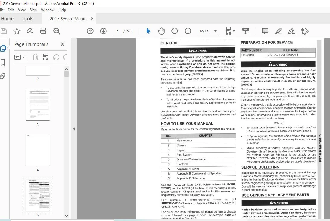
This service manual has been prepared with the following purposes in mind:
- To acquaint the user with the construction of the Harley-Davidson product and assist in the performance of basic maintenance and
repair. - To introduce the professional Harley-Davidson technician to the latest field-tested and factory-approved major repair methods.
We sincerely believe that this service manual will make your association with Harley-Davidson products more pleasant and profitable.
HOW ТО USE YOUR MANUAL
Refer to the tаЫе below for the content layout of this manual.
NO. CHAPTER
1 Maintenance
2 Chassis
3 Engine
4 Fuel System
5 Drive and Transmission
6 Electrical
А Appendix А Wiring
в Appendix В Compensating Sprocket
с Appendix С Reference
- Use the TABLE OF CONTENTS (which follows this FOREWORD) and the INDEX (at the back of this manual) to quickly locate subjects. Sections and topics in this manual are sequentially numbered for easy navigation.
- For example, a cross-reference shown as 2.1 SPECIFICATIONS refers to chapter 2 CHASSIS, heading 2.1 SPECIFICATIONS.
- For quick and easy reference, all pages contain a section number followed by a page number. For example, page 3-5 refers to page 5 in section 3.
- A number of acronyms and abbreviations are used in this document. See the D.1 GLOSSARY for a list of acronyms, abbreviations and definitions.
TABLE OF CONTENTS:
2017 Harley Davidson Sportster Models Service Manual – PDF DOWNLOAD
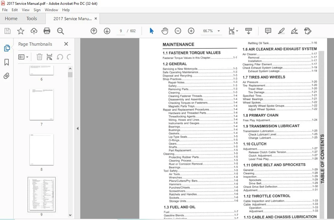
1 1 FASTENER TORQUE VALUES
Fastener Torque Values in this Chapter 1-1
1 2 GENERAL
Servicing а New Motorcycle 1-3
Safe Operating Maintenance 1-3
Disposal and Recycling 1-3
Shop Practices 1-3
Repair Notes 1-3
Safety 1-3
Removing Parts 1-3
Cleaning 1-3
Cleaning Fastener Threads 1-4
DisassemЫy and AssemЫy 1-4
Checking Torques оп Fasteners 1-4
Magnetic Parts Trays 1-4
Repair and Replacement Procedures 1-4
Hardware and Threaded Parts 1-4
Threadlocking Agents 1-4
Wiring, Hoses and Lines 1-4
lnstruments and Gauges 1-4
Bearings 1-4
Bushings 1-4
Gaskets 1-4
Lip-Type Seals 1-5
O-Rings 1-5
Gears 1-5
Shafts 1-5
Part Replacement 1-5
Cleaning 1-5
Protecting Rubber Parts 1-5
Cleaning Process 1-5
Rust or Corrosion Removal 1-5
Bearings 1-5
Tool Safety 1-5
Air Tools 1-5
Wrenches 1-6
Pliers/Cutters/Pry Bars 1-6
Hammers 1-6
Punches/Chisels 1-6
Screwdrivers 1-6
Ratchets and Handles 1-6
Sockets 1-6
Storage Units 1-6
1 3 FUEL AND OIL
Fuel 1-7
Gasoline Blends 1-7
Engine Lubrication 1-7
Low Temperature Lubrication 1-8
1 4 MAINTENANCE SCHEDULE
General 1-9
1 5 ENGINE OIL AND FILTER
Checking and Adding Oil 1-13
Removing and Replacing Oil Filler Сар 1-13
Oil Level Cold Check 1-13
Oil Level Hot Check 1-14
Changing Oil and Filter 1-14
Draining Oil Tank 1-14
Removing Oil Filter 1-15
lnstalling Oil Filter 1-15
Refilling Oil Tank 1-16
1 6 AIR CLEANER AND EXHAUST SYSTEM
Air Cleaner 1-17
Removal 1-17
lnstallation 1-17
Cleaning Filter Element 1-17
Check Exhaust System Leakage 1-19
Exhaust System Leakage 1-19
1 7 TIRES AND WHEELS
Air Pressure 1-20
Tire Replacement 1-20
Tread Wear 1-20
Тiге Damage 1-21
Specified Tires 1-21
Wheel Bearings 1-21
Wheel Spokes 1-22
ldentify Wheel Spoke Groups 1-22
Adjust Wheel Spokes 1-22
1 8 PRIMARY CHAIN
Free Play Adjustment 1-24
1 9 TRANSMISSION LUBRICANT
Transmission Lubrication 1-25
Check Lubricant Level 1-25
Change Lubricant 1-25 U)
1 10 CLUTCH
Adjustment 1-27
Release Clutch СаЫе Tension 1-27
Clutch Adjustment 1-27
Lever Free Play 1-28
1 11 DRIVE BELT AND SPROCKETS
General 1-29 W
Cleaning 1-29 J
lnspection 1-29 а]
Sprockets 1-29 ! Drive Belt 1-29
Check Drive Belt Deflection 1-30
Adjustment 1-31
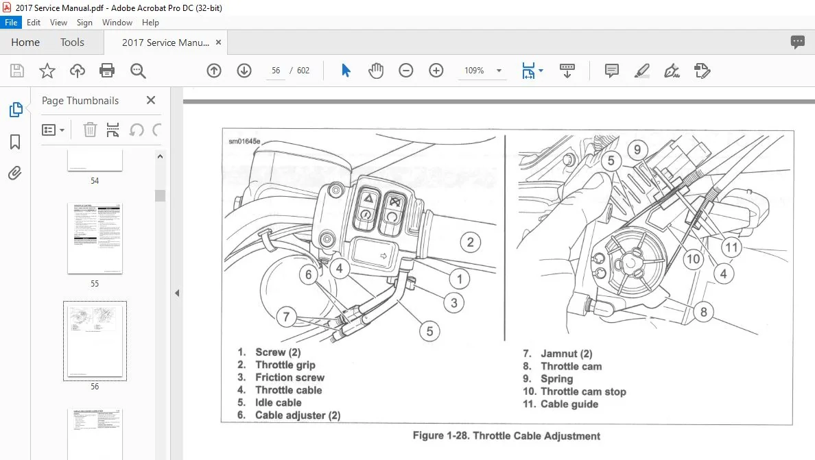
1 12 THROTTLE CONTROL
СаЫе lnspection and Lubrication 1-33
СаЫе Adjustment 1-33
Operation 1-33
Adjustment 1-33
1 13 CABLE AND CHASSIS LUBRICATION
General 1-35
СаЫеs and Hand Levers 1-35
Jiffy Stand 1-35
Steering Head Bearings 1-35
1 14 BRAKES
General 1-36
lnspect Brake Lines 1-36
Fluid Level 1-37
TrouЫeshooting 1-37
1 15 BRAKE PADS AND DISCS
lnspection 1-39
Brake Pads 1-39
V
TABLE OF CONTENTS
Brake Disc Thickness, Lateral Runout and
Warpage 1-39
Brake Pad Replacement: Front 1-39
Removal 1-39
1 nstallation 1-40
Brake Pad Replacement: Rear 1-41
Removal 1-41
lnstallation 1-42
1 16 SPARK PLUGS
Remove 1-43
lnspect 1-43
Clean 1-43
lnstallation 1-44
lnspect Spark Plug СаЫеs 1-44
1 17 STEERING HEAD BEARINGS
Fall-Away 1-45
Measurement 1-45
Adjustment 1-45
Lubrication 1-46
1 18 ENGINE MOUNTS AND STABILIZER
LINKS
1 nspection 1-4 7
1 19 BATTERY MAINTENANCE
General 1-48
Disconnection and Removal 1-49
Cleaning and lnspection 1-49
Voltage Test 1-49
Charging Battery 1-50
Safety Precautions 1-50
Using а Battery Charger 1-50
lnstallation and Connection 1-51
Storage 1-51
1 20 WHEEL ALIGNMENT
Wheel Alignment 1-53
Checking Wheel Alignment 1-53
Adjusting Wheel Alignment 1-54
1 21 SUSPENSION ADJUSTMENTS
Shock АЬsогЬег Preload: AII except XL 1200Т 1-55
ldentify Shock 1-55
ldentify the Preload Dot 1-55
Shock Adjustment 1-58
Shock Absorber Preload: XL 1200Т 1-59
1 22 HEADLAMP ALIGNMENT
Headlamp Alignment 1-61
Headlamp Adjustment 1-61
XL 1200С, XL 1200GB, XL 1200СХ, XL 1200Х
Models 1-61
XL883L, XL883N, XL 1200Т Models 1-62
1 23 STORAGE
Placing in Storage 1-63
Removal From Storage 1-63
VI TABLE OF CONTENTS
1 24 TROUBLESHOOTING
General 1-64
Engine 1-64
Starter Motor Does Not Operate ог Does Not Turn Engine
Over 1-64
Engine Turns Over But Does Not Start 1-64
Starts Hard 1-64
Starts But Runs lrregularly ог Misses 1-64
Spark Plug Fouls Repeatedly 1-64
Pre-lgnition ог Detonation (Knocks ог Pings) 1-65
Check Engine Light llluminates During Operation 1-65
Overheating 1-65
Valve Train Noise 1-65
Excessive Vibration 1-65
Lubrication System 1-65
Oil Does Not Return То Oil Tank 1-65
Engine Uses Тоо Much Oil Ог Smokes Excessively”1-65
Engine Leaks Oil From Cases, Pushrods, Hoses,
Etc 1-65
Low Oil Pressure 1-65
High Oil Pressure 1-66
Electrical System 1-66
Alternator Does Not Charge 1-66
Alternator Charge Rate Is Below Normal 1-66
Speedometer Operates Erratically 1 -66
Transmission 1-66
Shifts Hard 1-66
Jumps Out Of Gear 1-66
Clutch Slips 1-66
Clutch Drags Ог Does Not Release 1-66
Clutch Chatters 1-66
Handling 1-66
Brakes 1-66
Brake Does Not Hold Normally 1-66
CHASSIS
2 1 FASTENER TORQUE VALUES
Fastener Torque Values in this Chapter 2-1
2 2 SPECIFICATIONS
ТаЫеs 2-9
Chassis 2-9
Wheels and Tires 2-11
2 3 VEHICLE IDENTIFICATION NUMBER
(VIN)
Vehicle ldentification Number (VIN) 2-12
General 2-12
Location 2-12
Abbreviated VIN 2-12
2 4 TIRES
Remove 2-14
Clean, lnspect and Repair 2-14
lnstallation 2-14
Mounting 2-14
Tube Туре Тires 2-14
Tubeless Tires 2-15
Check Тiге Runout 2-15
Lateral Runout 2-15
Radial Runout 2-15
Balance Wheel 2-16
Static vs Oynamic 2-16
Weights 2-16
2 5 WHEELS
General 2-17
Wheel Bearing End Play 2-17
Front Wheel 2-18
Removal 2-18
DisassemЫy: Cast Front Wheel 2-19
AssemЫy: Cast Front Wheel 2-19
DisassemЫy: Laced Front Wheel 2-20
AssemЫy: Laced Front Wheel 2-20
lnstallation 2-21
Rear Wheel 2-22
Removal 2-22
DisassemЫy 2-22
Cleaning and lnspection 2-23
AssemЫy 2-23
lnstallation 2-24
Sealed Wheel Bearings 2-25
1 nspection 2-25
Removal 2-25
lnstallation 2-26
2 6 WHEEL LACING
Wheel Lacing: Angle Flange Hub 2-28
Wheel Lacing: Straight Flange Hub, Single Hole Circle 2-29
2 7 CHECКING AND TRUING WHEELS
Cast Wheel Runout 2-32
Wheel Stand 2-32
Lateral Runout 2-32
Radial Runout 2-32
Laced Wheel Rim Offset 2-33
True Laced Wheels 2-34
Adjust Radial Runout 2-34
Adjust Lateral Runout 2-35
2 8 FRONT BRAKE MASTER CYLINDER AND
RESERVOIR
lnspection 2-36
Removal 2-36
Front Brake Lever 2-37
Removal 2-37
lnstallation 2-37
Front Master Cylinder Reservoir Cover 2-37
Removal 2-37
lnstallation 2-37
Front Master Cylinder 2-38
DisassemЫy 2-38
Cleaning and lnspection 2-38
AssemЫy 2-39
lnstallation 2-39
2 9 FRONT BRAKE CALIPERS
Removal 2-42
DisassemЫy 2-42
Cleaning and lnspection 2-43
TABLE OF CONTENTS
AssemЫy 2-44
Pistons 2-44
Brake Caliper to Mounting Bracket 2-44
Brake Pads 2-45
lnstallation 2-45
2 1 О REAR BRAKE MASTER CYLINDER AND
RESERVOIR
lnspection 2-4 7
Removal 2-47
Cover 2-48
Removal 2-48
1 nstallation 2-48
Master Cylinder Rebuild Kit 2-48
DisassemЫy 2-48
Cleaning and lnspection 2-49
AssemЫy 2-49
Master Cylinder Mounting Bracket 2-50
Removal 2-50
lnstallation 2-50
lnstallation 2-50
2 11 REAR BRAKE CALIPER
Removal 2-52
DisassemЫy 2-52
Cleaning and lnspection 2-53
AssemЫy 2-53
lnstallation 2-54
2 12 BRAKE LINES
Front Brake Line (Non-ABS) 2-56
Removal 2-56
lnstallation 2-56
Front Brake Line Routing (Non-ABS) 2-58
XL 1200СХ 2-58
XL883L, XL883N, XL 1200С, XL 1200Т, XL 1200Х 2-58
XL 1200СВ with Mini-Ape Handlebar 2-59
Rear Вгаkе Line (Non-ABS) 2-59
Removal 2-60
lnstallation 2-60
Front Master Cylinder to Manifold to Caliper (ABS) 2 -61
Removal 2-61
1 nstallation 2-61
Front Manifold to EHCU (ABS) 2-63
Removal 2-63
lnstallation 2-63
Rear Master Cylinder to EHCU (ABS) 2-64
Removal 2-64
lnstallation 2-65
Rear EHCU to Caliper (ABS) 2-65
Removal 2-65
lnstallation 2-65
2 13 ELECTRO HYDRAULIC CONTROL UNIT
(EHCU)
Removal 2-67
1 nsta llation 2-68
2 14 BLEEDING BRAKES
General 2-69
Procedure 2-69
TABLE OF CONTENTS VII
TABLE OF CONTENTS
2 15 LEFT SIDE COVER
Opening and Closing 2-71
Open 2-71
Close 2-71
Replacement 2-71
Remove 2-71
Barrel Clip 2-71
lnstall 2-71
2 16 FRONT FORK
Check For Oil Leak 2-72
Fork Oil Seals 2-72
Check Oil Leak 2-72
Removal 2-72
DisassemЫy: Right Side, AII but XL 1200СХ 2-73
Drain Fork Oil 2-73
Fork DisassemЫy 2-73
DisassemЫy: Left Side, AII but XL 1200СХ 2-75
DisassemЫy: Left Side, XL 1200СХ 2-78
DisassemЫy: Right Side, XL 1200СХ 2-80
Clean and lnspect 2-81
AssemЫy: Right Side, AII but XL 1200СХ 2-82
Filling and Final AssemЫy 2-83
AssemЫy: Left Side, AII but XL 1200СХ 2-83
Filling and Final AssemЫy 2-84
AssemЬly: Left Side, XL 1200СХ 2-86
AssemЫy: Right Side, XL 1200СХ 2-87
lnstallation 2-90
2 17 FORK STEM AND BRACKET
ASSEMBLY
Removal and DisassemЫy 2-91
Cleaning, lnspection and Repair 2-91
AssemЫy and lnstallation 2-92
2 18 BELT GUARD AND DEBRIS
DEFLECTOR
Belt Guard 2-94
Removal 2-94
lnstallation 2-94
Debris Deflector 2-94
Removal 2-94
lnstallation 2-94
2 19 REAR FORK
Removal 2-95
lnstallation 2-95
Pivot Bearings 2-96
Removal 2-96
Cleaning and lnspection 2-96
lnstallation 2-96
Axle Adjusters 2-97
Removal 2-97
lnstallation 2-97
2 20 SHOCK ABSORBERS
Removal 2-98
Cleaning and lnspection 2-98
Preload Adjustment Knob: XL 1200Т 2-98
lnstallation 2-98
VIII TABLE OF CONTENTS
2 21 STABILIZER LINKS
General 2-100
Upper Front Stabllizer Link 2-100
Removal 2-100
DisassemЫy 2-100
AssemЫy 2-100
lnstallation 2-100
Lower Front Stabllizer Link 2-100
Removal 2-100
DisassemЫy 2-100
AssemЫy 2-100
lnstallation 2-1 О 1
Rear Stabllizer Link 2-101
Removal 2-101
lnstallation 2-101
2 22 FRONT ENGINE MOUNT AND
ISOLATOR
Removal 2-102
lnstallation 2-103
2 23 REAR ENGINE MOUNT AND ISOLATOR
Removal 2-104
lnstallation 2-105
2 24 THROTTLE CABLES
Removal 2-106
Throttle Adjusting Screw 2-107
Removal 2-107
lnstallation 2-107
Cleaning and lnspection 2-108
lnstallation 2-108
2 25 CLUTCH CONTROL
Removal and DisassemЫy 2-11 О
Clutch СаЫе: Lower 2-11 О
Clutch Lever and СаЫе: Upper 2-111
Clutch Hand Control 2-112
AssemЫy and lnstallation 2-113
Clutch Hand Control 2-113
Clutch Lever and Clutch СаЫе: Upper 2-113
Clutch СаЫе: Lower 2-113
2 26 HANDLEBAR
Removal 2-115
AII Models 2-115
XL 1200С 2-115
AII Models except XL 1200С 2-115
lnstallation 2-118
XL 1200С 2-118
AII Models except XL 1200С 2-118
AII Models 2-119
Left Hand Grip 2-119
Removal 2-119
lnstallation 2-119
2 27 FRONT FENDER
AII Models 2-120
2 28 FRONT LICENSE PLATE: INDIA
Front License Plate: lndia 2-122
XL883L, XL883N 2-122
XL 1200Х, XL 1200СХ 2-122
XL 1200С 2-122
2 29 SADDLEBAGS: XL 1200Т
Removal 2-124
Lockset 2-124
Reflectors and Medallions 2-124
Reflectors 2-124
Medallions 2-124
lnstallation 2-124
2 30 REAR FENDER: ТОР MOUNT LICENSE
PLATE ЕХС ЕРТ XL 1200Т, XL 1200С ,
XL1200CB
Removal 2-125
lnstallation 2-127
Fender Preparation 2-128
Tail Lamp AssemЫy 2-128
Seat Nut 2-128
Fender Extension 2-128
Wire Harness and Conduit 2-128
Тор Mount License Plate Bracket 2-128
Removal 2-128
lnstallation 2-128
2 31 REAR FENDER: XL 1200С , XL 1200С В
Replacement 2-129
Removal 2-129
lnstallation 2-130
Fender Preparation 2-131
Tail Lamp AssemЫy 2-131
Seat Nut 2-131
Fender Extension 2-131
Wire Harness 2-131
License Plate Bracket: XL 1200С, XL 1200СВ 2-131
2 32 REAR FENDER: XL 1200Т
Removal 2-132
lnstallation 2-133
Fender Preparation 2-134
Tail Lamp AssemЫy 2-134
Seat Nut 2-134
Fender Extension 2-134
Wire Harness 2-134
License Plate Bracket: XL 1200Т 2-134
Removal 2-134
lnstallation 2-134
2 33 REAR FENDER: MODELS WITH
INTEGRATED TURN SIGNAL, TAIL AND
STOP LAMPS
General 2-135
Removal and DisassemЫy 2-135
AssemЫy and lnstallation 2-137
2 34 WINDSHIELD : XL 1200Т
Windshield Removal and lnstallation: XL 1200Т 2-140
TABLE OF CONTENTS
Removal 2-140
1 nstallation 2-140
Cleaning 2-140
Windshield Replacement 2-141
DisassemЫy 2-141
AssemЫy 2-142
Mounting Clamps 2-142
Removal 2-142
lnstallation 2-142
2 35 SAREE GUARD: INDIA MODELS
Saree Guard 2-144
Right and Left-Rear 2-144
Left-Front 2-144
2 36 REAR LICENSE PLATE: INDIA MODELS
Rear License Plate: lndia 2-146
2 37 JIFFY STAND
Removal 2-147
Cleaning and Lubrication 2-147
lnstallation 2-148
2 38 SEAT
Removal 2-149
lnstallation 2-149
2 39 RIDER FOOT CONTROLS: MID-MOUNT
Right Footrest and Rear Brake Pedal AssemЫy 2-151
Removal 2-151
lnstallation 2-151
Left Footrest and Shift Lever AssemЬly 2-152
Removal 2-152
lnstallation 2-152
Footboard lnserts: XL 1200Т 2-154
Removal 2-154
lnstallation 2-154
2 40 RIDER FOOT CONTROLS: FORWARD
Right Footrest and Rear Brake Pedal AssemЫy 2-155
Removal 2-155
lnstallation 2-155
Left Footrest and Shift Lever AssemЫy 2-156
Removal 2-156
lnstallation 2-156
Adjusting Shift Pedal 2-158
2 41 PASSENGER FOOTRESTS
Left 2-159
Removal 2-159
lnstallation 2-159
Right 2-160
Removal 2-160
lnstallation 2-160
2 42 FORK LOCK
Removal 2-161
lnstallation 2-161
TABLE OF CONTENTS IX
TABLE OF CONTENTS
2 43 MEDALLIONS, BADGES AND TAN K
EMBLEMS
Removal 2-162
lnstallation 2-162
ENGINE
3 1 FASTEN E R TORQU E VALUES
Fastener Torque Values in this Chapter 3-1
3 2 SPECIFICATIONS
Specifications: Sportster Models 3-3
3 3 O I L PRESS U RE
Operation 3-7
AII Models 3-7
Oil Pressure lndicator Lamp 3-7
Checking Oil Pressure 3-8
Preparation 3-8
Connecting Gauge 3-8
Testing Pressure 3-8
Removing Gauge 3-8
Finalize Test 3-8
3 4 C RAN KCASE BREAT H I N G SYSTEM
Operation 3-1 о
3 5 TROUBLESHOOTI N G
Diagnosing Valve Train Noise 3-11
Compression Test 3-11
Cylinder Leakage Test 3-11
Diagnosing Smoking Engine ог High Oil Consumption 3-12
Check Prior to Cylinder Head Removal 3-12
Check After Cylinder Head Removal 3-12
Adjustment and Testing 3-12
General 3-12
3 6 E N G I N E LUBRICATION SYSTEM
Oil Pump Operation 3-13
Oil Flow 3-15
3 7 HOW ТО USE THIS SECTION
Typical Symptoms 3-19
Тор End Repair 3-19
Bottom End Repair 3-19
3 8 ТОР E N D SERVICE
Engine in Chassis 3-20
Engine Removed from Chassis 3-21
3 9 ваттом E N D SERVICE
Engine in Chassis 3-22
Engine Removed From Chassis 3-23
3 1 0 REMOVI N G E N G I N E FROM CHASSIS
Procedure 3-24
3 1 1 I N STALLING E N G I N E I N CHASSIS
Procedure 3-27
Х TABLE OF CONTENTS
3 1 2 ТОР E N D OVERHAU L : DISASSEMBLY
General 3-30
Stripping Motorcycle for Тор End Repair 3-30
Cylinder Heads 3-30
DisassemЫing Rocker Covers 3-30
Removing Cylinder Head 3-32
DisassemЫing Pushrods and Covers 3-33
Cylinder and Piston 3-34
3 1 3 CYLI N D E R H EAD
DisassemЬly 3-36
Cleaning and lnspection 3-36
Cylinder Heads 3-36
Rocker Arm AssemЫies 3-37
Valves 3-38
Valve Seats 3-38
Valve Guides 3-39
Valve Springs 3-39
Spark Plug Threads 3-39
Pushrods 3-39
Replacing Rocker Arm Bushings 3-39
Replacing Valve Guides 3-40
Removal 3-40
lnstallation 3-41
Refacing Valve Seats 3-44
Replacing Valve Seats 3-46
AssemЫy 3-46
3 1 4 CYL I N D E R AN D PISTON
Cleaning, lnspection and Repair 3-48
Checking Gasket Surface 3-48
Measuring Cylinder Воге 3-48
Measuring Piston to Cylinder Fit 3-49
Boring and Honing Cylinder 3-49
Fitting Piston Rings 3-50
Connecting Rod Bushings 3-52
Removing Upper Connecting Rod Bushings 3-52
lnstalling Upper Connecting Rod Bushings 3-53
Reaming Upper Connecting Rod Bushings 3-54
Honing Upper Connecting Rod Bushings 3-54
Repair 3-54
3 1 5 ТОР E N D OVERHAU L: ASSEMBLY
General 3-55
Piston and Cylinder 3-55
Tappet Covers, Pushrod Covers and Pushrods 3-56
Cylinder Head 3-58
Rocker Covers 3-59
lnner Cover 3-59
Breather 3-59
Outer Cover 3-60
AssemЫing Motorcycle After Тор End Repair 3-61
3 1 6 ваттом E N D OVERHAU L :
DISASSEMBLY
General 3-62
Oil Pump 3-62
Tappets 3-62
Cam Gear End Play 3-62
Gearcase Cover and Cam Gears 3-62
Crankcase 3-63
Split Crankcase 3-63
Piston Oil Jets 3-64
Removing Cylinder Base Studs 3-64
3 17 GEARCASE
Bushing lnspection and Removal 3-65
Bushing lnstallation 3-65
Cam Gear Bushings in Right Crankcase 3-65
Cam Gear Bushings (Except Rear lntake Bushing) in
Gearcase Cover 3-66
Rear lntake Cam Gear Bushing in Gearcase Cover 3-66
Pinion Shaft Bushing in Gearcase Cover 3-66
Bushing Reaming 3-66
Cam Gear Bushings in Right Crankcase 3-66
Cam Gear Bushings (Except Rear lntake Bushing) in
Gearcase Cover 3-67
Rear lntake Cam Gear Bushing in Gearcase Cover 3-67
Pinion Shaft Bushing in Gearcase Cover 3-68
3 18 CRANKCASE
General 3-69
DisassemЫy 3-69
Fitting Pinion Bearings 3-71
Outer and lnner Races 3-71
Bearing Selection 3-71
lnner Bearing Finish Example 3-73
Lapping Pinion Bearing Outer Race 3-74
3 19 OIL PUMP
General 3-76
Removal 3-76
DisassemЫy 3-77
Cleaning and lnspection 3-77
Asse m Ыу 3-77
lnstallation 3-78
3 20 ВОТТОМ END OVERHAUL: ASSEMBLY
Crankcase 3-79
lnstalling Piston Oil Jets 3-79
lnstalling Pinion Shaft Bearings 3-79
lnstalling Left Main Bearing 3-80
AssemЫing Crankcase Halves 3-81
lnstalling Cylinder Base Studs 3-83
Cam and Pinion Gear ldentification 3-83
Cam Gears and Gearcase Cover 3-83
Та р pets 3-86
General 3-86
Cleaning and lnspection 3-86
lnstallation 3-86
3 21 OIL FILTER MOUNT
General 3-88
DisassemЫy 3-88
Cleaning and lnspection 3-88
AssemЫy 3-88
3 22 OIL TANK
Pressure Relief Valve 3-89
Oil Line Routing 3-89
Crimp Clamps 3-89
Removal 3-89
TABLE OF CONTENTS
lnstallation 3-89
Removal 3-89
lnstallation 3-90
Oil Tank Bracket 3-91
Removal 3-91
lnstallation 3-91
F UE L SYSTE M
4 1 FASTENER TORQUE VALUES
Fastener Torque Values in this Chapter 4-1
4 2 SPECIFICATIONS: FUEL SYSTEM
Specifications 4-2
4 3 AIR CLEANER ASSEMBLY
AII Models 4-3
Removal 4-3
lnstallation 4-3
4 4 FUEL TANK
Purging and Disconnecting Fuel Supply Line 4-4
Removing Fuel Tank 4-4
Cleaning and lnspection 4-5
lnstalling Fuel Tank 4-5
Connecting Fuel Hose and Filling Fuel Tank 4-6
Vapor Valve 4-8
General 4-8
Removal 4-8
lnstallation 4-8
4 5 THROTTLE POSITION SENSOR (TPS)
General 4-9
Removal 4-9
lnstallation 4-9
4 6 ENGINE TEMPERATURE (ЕТ) SENSOR
General 4-11
Removal 4-11
1 nstallation 4-12
4 7 INDUCTION MODULE
Removal 4-13
DisassemЫy 4-15
AssemЫy 4-16
lnstallation 4-16
4 8 IDLE AIR CONTROL (IAC)
General 4-19
Removal 4-19
lnstallation 4-20
4 9 TEMPERATURE MANIFOLD ABSOLUTE
PRESSURE (TMAP) SENSOR
General 4-21
Removal 4-21
lnstallation 4-21
4 1 О HEATED OXYGEN SENSOR (НО25)
Removal 4-23
TABLE OF CONTENTS XI
TABLE OF CONTENTS
lnstallation 4-23 Charcoal Canister 4-43
Removal 4-43
4 11 FUEL INJECTORS lnstallation 4-44
Removal 4-25 Fuel Vapor Vent Hose 4-44
lnstallation 4-26 Removal
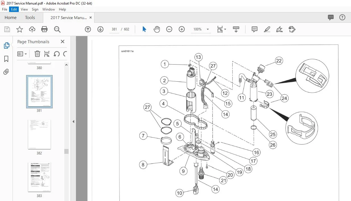
4 12 FUEL PUMP
General 4-28
Removal 4-28
DisassemЫy 4-29
Pressure Regulator and Filter Housing 4-29
Fuel Pump AssemЫy and Pump Bracket 4-29
Low Fuel Level Sensor AssemЫy 4-29
AssemЫy 4-30
Low Fuel Level Sensor AssemЫy 4-30
Fuel Pump AssemЫy and Pump Bracket 4-30
Pressure Regulator and Filter Housing 4-30
lnstallation 4-31
4 13 FUEL FILTER ELEMENT
General 4-33
Removal 4-33
lnstallation 4-33
4 14 FUEL PRESSURE TEST
General 4-34
Testing 4-34
Connect Fuel Pressure Gauge 4-34
Perform Test 4-34
Return to Service 4-35
4 15 INTAKE LEAK TEST
General 4-37
Leak Tester 4-37
Parts List 4-37
AssemЫe Tester 4-37
Adjust Tester 4-37
Procedure 4-37
4 16 EXHAUST SYSTEM
Unit Removal 4-39
Exhaust Shields 4-40
Removal: 4-40
1 nstallation 4-40
Muffier Shields 4-40
Removal 4-40
lnstallation 4-40
Mufflers 4-40
Removal 4-40
1 nstallation 4-40
Exhaust Pipes 4-41
Removal 4-41
lnstallation 4-41
Exhaust Pipe Bracket 4-41
Mounting Bracket 4-42
Removal 4-42
lnstallation 4-42
4 17 EVAPORATIVE (EVAP) EMISSIONS
CONTROL
General 4-43
XII TABLE OF CONTENTS
lnstallation 4-44
Canister-to-Solenoid Hose 4-44
Removal 4-44
lnstallation 4-44
Solenoid-to-lnduction Module Hose 4-44
Removal 4-44
1 nstallation 4-44
Purge Solenoid 4-45
Removal 4-45
1 nstallation 4-45
DRIVE AND TRANSM ISS ION
5 1 FASTENER TORQUE VALUES
Fastener Torque Values in this Chapter 5-1
5 2 SPECIFICATIONS: DRIVE
Sportster Specifications 5-2
5 3 PRIMARY COVER
Removal 5-3
Clutch Release Ramp 5-4
Primary Chain Adjuster 5-5
lnstallation 5-5
5 4 PRIMARY DRIVE AND CLUTCH
TrouЫeshooting 5-7
Removal 5-7
DisassemЫy 5-9
lnspection and Repair 5-9
AssemЫy 5-10
lnstallation 5-11
5 5 DRIVE BEL Т
Drive Belt Handling 5-13
Drive Belt 5-13
Removal 5-13
lnstallation 5-14
5 6 TRANSMISSION POWER FLOW
General 5-15
5 7 CASE DISASSEMBLY FOR
TRANSMISSION REMOVAL
General 5-16
Engine Removal and DisassemЬly 5-16
5 8 TRANSMISSION REMOVAL AND
DISASSEMBLY
Transmission Removal From Left Crankcase 5-19
Cleaning and lnspection 5-20
Mainshaft DisassemЫy 5-20
Countershaft DisassemЫy 5-21
5 9 TRANSMISSION ASSEMBLY
Mainshaft AssemЫy 5-23
Countershaft AssemЫy 5-23
5 1 О MAIN DRIVE GEAR AND BEARING
General 5-25
Removal 5-26
Main Drive Gear 5-26
Main Drive Gear Ball Bearing 5-27
DisassemЫy 5-27
AssemЫy 5-28
1 nstallation 5-29
Main Drive Gear Bearing 5-29
Main Drive Gear 5-29
Main Drive Gear Seal 5-31
5 11 TRANSMISSION RIGHT CASE
BEARINGS
Removal 5-34
Countershaft Needle Bearing 5-34
Shifter Drum Bushing 5-34
1 nstallation 5-34
Countershaft Needle Bearing 5-34
Shifter Drum Bushing 5-34
5 12 TRANSMISSION LEFT CASE BEARINGS
Removal 5-35
Mainshaft and Countershaft Bearings 5-35
Shifter Drum Bushing 5-35
1 nstallation 5-35
Mainshaft and Countershaft Bearings 5-35
Shift Drum Bushing 5-35
5 13 TRANSMISSION INSTALLATION
General 5-36
lnstallation 5-36
Shifter Forks and Drum AssemЫy 5-37
AssemЫing Crankcases 5-38
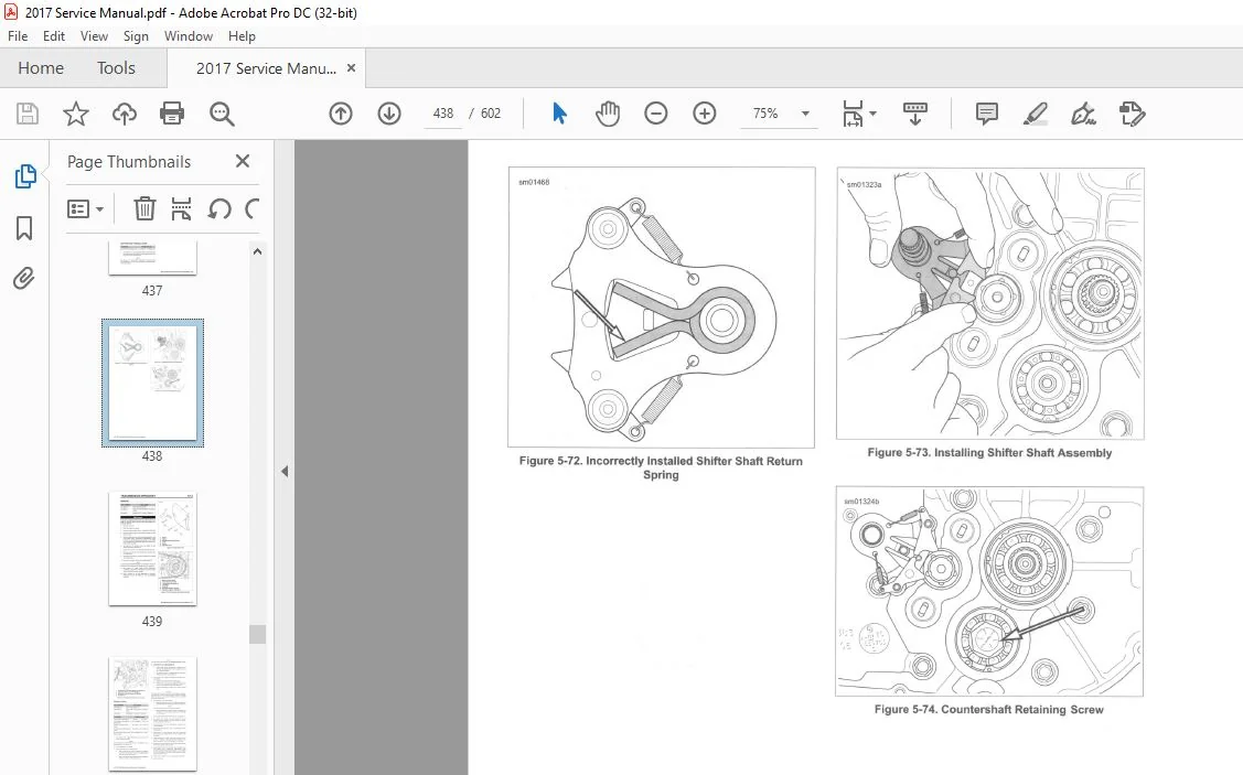
Shifter Shaft lnstallation 5-39
5 14 TRANSMISSION SPROCKET
Removal 5-41
lnstallation 5-42
ELECTRICAL
6 1 FASTENER TORQUE VALUES
Fastener Torque Values in this Chapter 6-1
6 2 SPECIFICATIONS: ELECTRICAL
Specifications 6-5
6 3 FUSES
Replacement 6-6
Removal 6-6
lnstallation 6-6
6 4 SPEEDOMETER
Removal 6-7
TABLE OF CONTENTS
XL883L, XL883N, XL 1200СВ and XL 1200Т 6-7
XL 1200Х, XL 1200СХ 6-7
XL 1200С 6-7
lnstallation 6-7
XL883L, XL883N, XL 1200GB, XL 1200Т 6-7
XL 1200Х, XL 1200СХ 6-7
XL 1200С 6-8
6 5 ELECTRONIC CONTROL MODULE (ЕСМ)
Removal 6-9
lnstallation 6-9
6 6 BODY CONTROL MODULE (ВСМ)
Removal 6-1 О
lnstallation 6-1 О
6 7 H-D555
Activation 6-12
Antenna 6-12
Fob Battery 6-12
Battery Replacement Schedule 6-12
Battery Replacement 6-12
6 8 PERSONAL IDENTIFICATION NUMBER
(PIN)
General 6-13
Changing The PIN 6-13
Modifying an Existing PIN 6-13
6 9 SMART SIREN
Replacement 6-15
Removal 6-15
lnstallation 6-15
Battery 6-15
Replacement Schedule 6-15
Replacement 6-15
6 10 BATTERY CABLES
Negative Battery СаЫе 6-17
Removal 6-17
lnstallation 6-17
Positive Battery СаЫе 6-17
Removal 6-17
lnstallation 6-18
6 11 BATTERY TRAY
Removal 6-19
lnstallation 6-19
6 12 STARTER
Removal 6-20
Touch-Up Paint 6-20
lnstallation 6-20
Solenoid 6-21
Remove Cover and Plunger 6-21
Short Post Contact: Starter 6-21
Long Post Contact: Battery Positive 6-21
lnstall Plunger and Cover 6-22
Clutch Shaft AssemЫy 6-22
Removal 6-22
lnspection 6-22
TABLE OF CONTENTS XIII
TABLE OF CONTENTS
lnstallation 6-22
6 1 З IGNITION SWITCH
Removal 6-24
lnstallation 6-24
6 14 SPARK PLUG CABLES
General 6-25
Removal 6-25
lnstallation 6-26
6 15 IGNITION COIL
General 6-27
Removal 6-27
1 nstallation 6-28
6 16 HEADLAMP
Bulb Replacement 6-29
Hi/Low Beam 6-29
Position Lamp: HDl 6-29
Headlamp Mounts 6-30
Mount: XL883L, XL883N, XL 1200Т 6-30
Mount: XL 1200СХ, XL 1200Х 6-31
Mount: XL 1200С, XL 1200СВ 6-31
Visor: XL 1200С, XL 1200СВ 6-31
6 17 INDICATOR LAMP MODULE
Preliminary DisassemЫy 6-32
Replacement: XL883L, XL883N, XL 1200GB, XL 1200Т,
XL 1200Х, XL 1200СХ 6-32
Replacement: XL 1200С 6-33
AssemЫy 6-34
6 18 TAIL LAMP: MODELS WITH
TOP-MOUNT LICENSE PLATE
Bulb Replacement: XL883L, XL 1200Т 6-35
Base Replacement: XL883L, XL 1200Т 6-35
Rear Lighting Harness 6-36
Removal 6-36
lnstallation 6-37
LED Tail Lamp: XL 1200С, XL 1200СВ 6-37
Removal 6-37
1 nstallation 6-38
6 19 LICENSE PLATE LAMP MODULE
General 6-39
Removal: Side-Mount License Plate 6-39
lnstallation: Side-Mount License Plate 6-40
Removal: Center-Mount License Plate 6-40
lnstallation: Center-Mount License Plate 6-43
Reflector Brackets 6 -44
Removal 6-44
1 nstallation 6-44
6 20 FRONT TURN SIGNALS
Bulb Replacement 6-45
Front Turn Signal Wire Harness 6-45
Removal 6-45
lnstallation 6-45
AII Except XL 1200Т, XL 1200Х 6-46
Removal 6-46
XIV TABLE OF CONTENTS
lnstallation 6-46
XL 1200Х 6-46
Removal 6 -46
lnstallation 6-46
XL 1200Т 6-47
Removal 6-47
DisassemЫy 6 -47
AssemЫy 6-4 7
lnstallation 6-48
6 21 REAR TURN SIGNALS
General 6-49
Bulb Replacement 6-49
Tail and Stop Lamps 6 -49
XL883L 6-49
Removal 6-49
lnstallation 6-50
XL 1200Т 6-51
Removal 6-51
DisassemЫy 6-51
AssemЫy 6-51
1 nstallation 6-52
XL883N, XL 1200Х 6-53
Removal 6-53
lnstallation 6-54
XL 1200С, XL 1200СВ 6-55
Removal 6-55
1 nstallation 6-56
XL 1200СХ 6-56
Removal 6-56
lnstallation 6-57
6 22 REAR STOP LAMP SWITCH
Removal 6-59
Stop Lamp Switch 6-59
Wire Harness 6-59
lnstallation 6-59
Wire Harness 6-59
Stop Lamp Switch 6-59
6 23 CRANK POSITION SENSOR (СКР)
General 6-61
Removal 6-61
lnstallation 6 -61
6 24 VOLTAGE REGULATOR
Removal 6-62
lnstallation 6-62
6 25 ALTERNATOR
Removal and DisassemЫy 6-63
Stator 6-63
Rotor 6-63
Cleaning and lnspection 6-64
AssemЫy and lnstallation 6-64
Stator 6-64
Rotor 6-64
Final AssemЫy 6-65
6 26 VEHICLE SPEED SENSOR (VSS)
Removal 6-66
1 nstallation 6-66
6 27 WHEEL SPEED SENSOR (WSS)
Front WSS 6-67
Removal 6-67
lnstallation 6-67
Rеаг WSS 6-68
Removal 6-68
lnstallation 6-68
6 28 NEUTRAL INDICATOR SWITCH
General 6-69
Replacement 6-69
6 29 MAIN WIRING HARNESS AND
ELECTRICAL CADDIES
Removal 6-70
Backbone Electrical Caddies 6-71
Preparation 6-71
Small Backbone Electrical Caddy 6-71
Large Backbone Electrical Caddy 6-71
ReassemЫy 6-71
Replacing ЕСМ Electrical Caddy 6-72
Removal 6-72
lnstallation 6-72
lnstallation 6-73
J-Clips: Mid-Mount Models 6-76
6 30 JIFFY STAND SENSOR (JSS) :
INTERNATIONAL MODELS
Removal 6-77
1 nstallation 6-77
Operation 6-78
Jiffy Stand Down: Engine Non-Start 6-78
Jiffy Stand Down: Engine Starts and Stalls 6-78
Jiffy Stand Drops 6-78
6 31 OIL PRESSURE SWITCH
General 6-79
Removal 6-79
lnstallation 6-79
6 32 HORN
Front Mount 6-80
Removal 6-80
lnstallation 6-80
Side Mount 6-81
Removal 6-81
lnstallation 6-81
6 33 RIGHT HANDLEBAR CONTROL
MODULE
Removal 6-83
Right Handlebar Control Кеу Caps 6-84
START/Hazard and Turn Signal 6-84
OFF/RUN 6-84
Front Stop Lamp Switch Replacement 6-84
lnstallation 6-84
TABLE OF CONTENTS
6 34 LEFT HANDLEBAR CONTROL MODULE
Removal 6-86
Left Handlebar Control Кеу Caps 6-86
TRIP/HORN and Turn Signal 6-86
LIGHTS 6-87
Clutch Switch Replacement 6-87
lnstallation 6-87
A PPENDI X А WI RING
А 1 CONNECTORS
Connector Locations A-1
Function/Location А-1
Place and Color A-1
Connector Number A-1
Repair lnstructions А-1
А 2 WIRING DIAGRAMS
Wiring Diagram lnformation A-4
Wire Color Codes А-4
Wiring Diagram Symbols А-4
2017 Sportster Wiring Diagrams А-6
A PPENDI X В CO MPENSATING
S PROC KET
В 1 FASTENER TORQUE VALUES
Fastener Torque Values in this Chapter 8-1
В 2 COMPENSATING SPROCKET
General 8-2
Removal and DisassemЫy В-2
Cleaning, lnspection and Repair 8-2
Sprocket Bearing 8-2
Removal 8-2
lnstallation 8-3
AssemЫy and lnstallation В-3
A PPENDI X С REFE RENCE
С 1 METRIC CONVERSION
Conversion ТаЫе С-1
С 2 FLUID CONVERSION
United States System C-2
Metric System С-2
British lmperial System C-2
С З TORQUE CONVERSION
United States System C-3
Metric System С-3
С 4 GLOSSARY
Acronyms and Abbreviations С-4
REFE RENCE MATE RI A L
TOOLS I
TABLE OF CONTENTS XV
TABLE OF CONTENTS
TORQUE VALUES V II INDEX x xv
XVI TABLE
2017 HARLEY DAVIDSON SPORTSTER MODELS SERVICE MANUAL – PDF DOWNLOAD:
PLEASE NOTE:
- This is the SAME MANUAL used by the dealerships to diagnose your vehicle
- No waiting for couriers / posts as this is a PDF manual and you can download it within 2 minutes time once you make the payment.
- Your payment is all safe and the delivery of the manual is INSTANT – You will be taken to the DOWNLOAD PAGE.
- So have no hesitations whatsoever and write to us about any queries you may have : heydownloadss @gmail.com
S.V