
2018 Textron Off Road Stampede Technicians Repair And Service Manual – PDF DOWNLOAD
Original price was: $89.00.$26.95Current price is: $26.95.
2018 Textron Off Road Stampede Technicians Repair And Service Manual – PDF DOWNLOAD
Description
2018 Textron Off Road Stampede Technicians Repair And Service Manual – PDF DOWNLOAD
DESCRIPTION:
2018 Textron Off Road Stampede Technicians Repair And Service Manual – PDF DOWNLOAD
SAFETY INSTRUCTIONS:
This manual has been designed to assist in the maintenance of the vehicle in accordance with procedures developed by the manufacturer. Following these procedures and troubleshooting tips will ensure the best possible service from the product To reduce the chance of personal injury and/or property damage, the following instructions must be carefully observed:
GENERAL :
Many vehicles are used for a variety of tasks beyond their original intended use; therefore it is impossible to anticipate and warn against every possible combination of circumstances that may occur. Warnings cannot replace good com- mon sense driving practices- Common sense driving practices do more to prevent accidents and injury than warnings and instructions can provide.
- The manufacturer strongly suggests anyone operating the vehicle read the entire owner’s manual provided with the purchase of the vehicle, paying particular attention to the CAUTIONS, WARNINGS and DAN GERS within- For any questions or concerns, contact your dealer. Textron Specialized Vehicles, Inc. reserves the right to make design changes without obligation to make these changes on units previously sold and the information in this manual is subject to change without notice.
- Textron Specialized Vehicles, Inc. is not liable for errors in this manual or for incidental or consequential damages that result from the use of the material in this manual. This vehicle conforms to the current applicable standard for safety and performance requirements.
- This vehicle is designed and manufactured for off road use- It does not conform to Federal Motor Vehicle Safety Standards and is not intended for operation on public streets. Refer to GENERAL SPECIFICATIONS for vehicle seating capacity. Do not exceed number of occupants indicated.
TABLE OF CONTENTS:
2018 Textron Off Road Stampede Technicians Repair And Service Manual – PDF DOWNL5 To fill the lower chamber to capacity, add an additional 22 oz (650 ml) through the speed sensor hole 104
6 Replace the speed sensor 104
Rear Differential Replacement 105
Fig 17 Rear Differential Mounting Brackets 105
1 Remove the cargo deck, skid plate, side panels and fender liner See BODY on page 15 105
2 Remove the truck bed See TRUCK BED on page 45 105
3 Remove the muffler and heat shields See EXHAUST SYSTEM REMOVAL on page 117 105
4 Remove the rear frame cross-member See FRAME on page 31 105
5 Remove the CVT clutches, air hoses and belt See CONTINUOUSLY VARIABLE TRANSMISSION (CVT) on page 99 106
6 Remove the prop-shaft See Prop-shaft Removal on page 106 106
7 Lift and support the vehicle See LIFTING THE VEHICLE on page 13 106
8 Remove the rear wheels See Wheel Removal on page 54 106
9 Remove the CV shaft See CV Shaft Replacement on page 88 106
10 Disconnect the differential vent hoses (Ref Fig 18) 106
Fig 18 Disconnect Vent Hoses 106
11 Remove the bolts (10 and 11) and nuts (12) that secure the shifter bracket (22) to the differential brackets (1 and 9) (Ref Fig 17)(Ref Fig 20) 106
12 Disconnect the shifter linkage (Ref Fig 19) (Ref Fig 20) 106
Fig 19 Shifter Linkage 106
Fig 20 Remove Shifter Bracket 106
13 Disconnect the speed sensor wire (Ref Fig 22) 106
Fig 21 Disconnect Speed Sensor 107
14 Disconnect the differential lock wire (Ref Fig 21) 107
Fig 22 Disconnect Differential Lock 107
15 Use a ratchet strap to secure the engine to the rear upper ROPS crossbar for support (See Fig 23) 107
Fig 23 Support Engine with Ratchet Strap 107
16 Remove the bolts (5, 10 and 11) and nuts (6) that secure the upper passenger side differential bracket to the engine and differential (Ref Fig 17) 107
17 Remove the bolt (5) and nut (6) from the lower differential mounting bracket (1) 107
Fig 24 Remove Differential Bracket 107
18 Remove the four bolts (17) and nuts (18) that secure the driver side differential bracket (15) to the engine stator cover (See Fig 17)(See Fig 24)(Ref Fig 25) 107
Fig 25 Differential Mounting Bolts 108
19 Remove the bolt (25), washer and nut that secure the differential to the rear engine mount (See Fig 17)(Ref Fig 26) 108
Fig 26 Rear Engine Mount 108
20 With the aid of an assistant, hoist the rear differential up and out of the vehicle 108
21 Installation of the differential is in the reverse order of removal 108
22 Tighten the hardware to the torque values specified: 108
Adjusting the Shift Lever Cable 108
Fig 27 Shift Lever 108
Fig 28 Shift Cable 109
Primary Clutch 111
Secondary Clutch 111
Increased Load 111
Equilibrium 111
Fig 1 CVT Components 112
CVT Belt Break-in 113
CVT Belt Inspection 113
Fig 2 CVT Belt 113
1 Remove the air outlet and inlet hoses from the CVT cover 113
2 Remove the CVT cover screws (17) and the CVT cover to access the CVT belt 113
3 Inspect the belt The CVT belt will require no service unless the vehicle has been operated in an extremely dusty or muddy location, in which case it should be washed with plain water If the belt becomes frayed or badly worn, it must be replaced 113
CVT Belt Replacement 113
Fig 3 Removing the CVT Belt 113
Primary Clutch Removal 113
1 Remove the CVT belt See CVT Belt Replacement on page 101 114
2 Use a pry bar or a strap wrench to prevent the primary clutch from turning Remove bolt (19), lock washer (20) and flat washer (21) securing the primary clutch to the engine crankshaft (Ref Fig 4) 114
Fig 4 Primary Clutch Removal 114
3 Insert the clutch puller tool and tighten (clockwise) which will remove the clutch from the engine crankshaft (Ref Fig 5) 114
Fig 5 Clutch Tool 114
Primary Clutch Installation 114
1 Clean both the engine crankshaft and the primary clutch bore Slide the clutch onto the crankshaft 114
2 Install the lock washer (20), large flat washer (21) and bolt (19) 114
3 Use a strap wrench to hold the clutch when tightening bolt (19) 114
4 Tighten bolt (19) to the torque value specified: 114
Secondary Clutch Removal 115
1 Remove the screws (17) that secure the clutch cover to the backing plate Remove the clutch cover 115
2 Remove the CVT belt 115
3 Remove the secondary clutch bolt (18), and slide the clutch from the rear differential input shaft (Ref Fig 6) 115
Fig 6 Secondary Clutch Removal 115
Secondary Clutch Installation 115
1 Coat the rear axle input shaft with a light coat of anti- seize compound and slide the clutch onto the shaft 115
2 Install the clutch bolt (18) and tighten to the torque value specified: 115
Draining the CVT 115
1 Park the vehicle on a level surface and move the gear shifter to the P (park) position 115
2 Remove the drain plug (12) from the bottom of the CVT cover 115
3 Allow the water to drain completely 115
4 After all of the water has drained out, replace the drain plug 115
5 Start the engine 115
6 Allow the vehicle to idle for 20 – 30 seconds to remove moisture from the clutch system 115
7 Apply the brakes 115
8 Move the gear shifter to L (low) range 115
9 Test for belt slippage If the belt slips, repeat the process 115
10 Take the vehicle to your dealer for service as soon as possible 115
Fig 1 Front and Rear Prop-Shaft 118
GENERAL 118
Prop-shaft Maintenance 118
Prop-shaft Removal 118
1 Place the vehicle on a flat level surface 118
2 Move shifter to the P (park position) and remove the key from the vehicle 118
3 Chock the wheels to prevent the vehicle from rolling 118
4 Remove the skid plate See Skid Plate Removal on page 28 118
Fig 2 Mid-Shaft Bearing 118
5 Remove the nut (4) and bolt (5) securing each side of the mid-shaft bearing (3) to the frame (Ref Fig 1) (Ref Fig 2) 118
6 Remove bolt (6) and lock nut (7) from the front of the front prop-shaft (1) where it connects the front differential (See Fig 1) (Ref Fig 3) 118
Fig 3 Disconnect Front Prop-Shaft 119
7 Slide front prop-shaft off the front differential 119
8 Slide rear prop-shaft off of the rear differential (Ref Fig 4) 119
Fig 4 Disconnect Rear Prop-Shaft 119
9 Remove the front and rear prop-shafts from the vehicle 119
10 Installation is the reverse of removal Clean the prop- shaft, gearbox and differential splines with a clean rag Apply fresh grease to the splines before installation 119
11 Tighten the hardware to the torque values specified: 119
Fig 1 Engine 121
Engine Specifications 122
Engine Oil Type and Capacity 122
Checking the Engine Oil Level 122
1 Use a cloth to clean the top of the oil tank and the top of the dipstick This is necessary to prevent debris from falling into the oil tank 122
2 Start the engine and let it to run until it is warm (approximately five (5) minutes) 122
3 Turn off the engine 122
4 Remove the dipstick from the oil tank (Ref Fig 2) 122
Fig 2 Engine Oil Tank and Dipstick 123
5 To get an accurate oil level reading, wipe the oil from the dipstick and insert it back into the oil tank Do not tighten the dipstick 123
6 Remove the dipstick from the tank again and check the level The oil level must be in the area between the MIN and MAX markings on the dipstick (Ref Fig 3) 123
Fig 3 Dipstick 123
7 If the oil level is below the MIN line, add engine oil into the dipstick hole until the level is between MIN and MAX 123
8 If the oil level is above the MAX line, pump out the excessive oil with a siphon pump 123
9 When the level is correct, replace and tighten the dipstick 123
Remove Engine Oil 123
1 Start the engine and let it to run until it is warm 123
2 Turn off the engine 123
3 Remove the engine oil 123
a Put a drain pan under the oil tank 123
Fig 4 Oil Tank Drain Plug and Seal 123
b Remove the drain plug and seal (Ref Fig 4) 123
c Allow the oil to completely drain from the tank into the pan 123
Fig 5 Service Fuse 124
d Remove the 15Amp service fuse in the main fuse box under the driver seat Removing this fuse will interrupt the power supply circuit to the ignition coil, injectors and O2 sensor so that the engine will turn over without starting (Ref Fig 5) 124
e Turn the key to activate the starter for five seconds As the engine turns over, oil is pumped out of the engine 124
f Let the oil drain until it stops and then repeat two more times to remove the remaining oil from the tank 124
g When all of the oil is pumped out of the tank, replace the seal and reinstall the drain plug Tighten the plug to 13 3 – 14 8 ft lb (18 – 20 Nm) 124
Replace the Oil Filter 124
Fig 6 Replace Oil Filter 124
1 Remove the oil filter with universal strap wrench (Ref Fig 6) 124
2 Clean the engine sealing surface with a clean cloth (Ref Fig 7) 124
Fig 7 Oil Filter 124
3 Lightly coat the new oil filter seal with clean engine oil 124
4 Install the oil filter and tighten to 7 4 ft lb (10 Nm) 124
Refill Engine Oil 124
Fig 8 Add Oil 124
1 Add new engine oil into the dipstick hole Install the dipstick 124
2 Replace the 15 Amp service fuse 124
3 Verify that the oil level is correct 124
4 Clear the service counter for the service light 124
5 Clear the trouble codes 124
6 Test drive the vehicle and check for leaks 124
Fig 9 Air Filter 125
1 Remove the seat bottom to access the air filter housing that is located below the driver seat 125
2 Unlatch the cover to access the air filter cartridge 125
3 Remove the filter from the housing (Ref Fig 9) 125
4 Inspect the filter Replace if dirty or at the first sign of filter paper deterioration Light dust or debris may be removed by lightly tapping out the dust Do not use compressed air on the filter 125
5 Check for loose, clogged or damaged air intake hoses 125
6 If necessary, vacuum or wipe out any loose dirt or debris from the air cleaner housing and cover 125
7 Reinstall or replace the filter Make sure the filter is fully seated in the housing 125
8 Replace the housing and secure with latches 125
9 Replace the seat bottom 125
1 With the engine cool, remove and inspect the spark plugs See SCHEDULED MAINTENANCE CHART on page 166 125
2 Clean and gap the spark plugs to 0 028 – 0 032″ (0 69 – 0 84mm) (Ref Fig 10) If a plug has been burned beyond 0 032″ (0 84 mm) or if the porcelain insulator is cracked, both plugs should be replaced 125
3 Lightly coat the threads with anti-seize compound 125
4 Tighten spark plugs to 16 2 – 23 6 ft lbs (22 – 32 Nm) torque 125
Fig 10 Spark Plug Gap 125
Spark Plug Inspection and Replacement 125
Fig 11 Ignition Coils 125
1 Disconnect the engine from the power supply 125
2 Disconnect the wire harness connectors from the ignition coils (Ref Fig 11) 125
3 Remove the bolts and washers securing the ignition coils to the engine (Ref Fig 12) 126
Fig 12 Remove Ignition Coil 126
4 Pull straight up on the ignition coils to remove them from the engine 126
5 Remove the spark plugs with a spark plug socket (Ref Fig 13) 126
Fig 13 Spark Plug 126
6 If the electrodes are extremely sooty, clean carefully with a wire brush 126
7 Determine the condition of the spark plugs by checking the gap with a feeler gauge The gap must be within the range indicated in the illustration 126
8 Apply a light film of ant-seize on the threads of the spark plugs Install the spark plugs and tighten to 16 2 – 23 6 ft lb (22 – 32 Nm) 126
9 Insert the ignition coils 126
10 Replace the serrated washers with new ones Install the bolts, washers and serrated lock washers and tighten to 5 9 – 7 4 ft lb (8 – 10 Nm) 126
11 Reconnect the wire harness to the ignition coils 126
12 Reconnect the power supply to the engine 126
13 Clear the service counter for the service light (See the Stampede 900 Owner’s Manual) 126
1 Lift the entire vehicle See THE SAFETY section for the procedure to lift the vehicle 126
2 Place the shifter in the P (park) position 126
3 Run the engine until it reaches normal operating temperature and then turn it off 126
4 Disconnect the fuel line from the fuel tank and plug the line to prevent contamination Run the engine until the fuel is depleted 126
5 Remove the air filter to eliminate the possibility of a restricted air passage 126
6 A good, well charged battery should be used A weak battery may not provide the correct cranking speed 126
7 Install a compression tester Follow the tester manufacturer’s instructions for use 126
8 Turn the engine over Make sure the throttle is fully open to let air in Make sure the reading is normal per the engine manual compression specifications If the compression reading is low, check for correct valve adjustment If the valves are pr 126
Fig 14 Engine Mounting Components 127
Fig 15 Exhaust System 129
1 Remove the truck bed from the vehicle See TRUCK BED REMOVAL on page 46 130
2 Remove the three springs (13) that secure the exhaust pipe (14) to the exhaust manifold (2) (Ref Fig 15) 130
3 Remove the three springs (13) that secure the muffler (1) to the exhaust pipe (14) 130
4 Remove the nut (21) that secure the J-hook (20) to the frame Rotate the J-hook out of the isolator hangers (3) 130
5 Remove the nuts (12) and bolts (25) that secure the muffler support bracket (19) to the frame 130
6 Remove the exhaust pipe (14) 130
7 Disconnect the oxygen sensor (9) 130
8 Remove the bolt (24) that secures the exhaust manifold (2) to the manifold bracket (18) 130
9 Remove the bolts (6) that secure the exhaust manifold (2) to the engine Remove the manifold and gaskets (7) from the engine 130
10 Install new exhaust manifold gaskets (7) onto the engine studs 130
11 Place the exhaust manifold onto the engine studs Secure the manifold to the engine with nuts (6) 130
Fig 16 Exhaust Manifold Installation 130
12 Install the exhaust pipe and muffler in the reverse order of removal Use new gasket (15) Tighten the hardware to the torque values specified 130
Fig 1 Air Intake Components 133
Air Filter Maintenance 134
Fig 2 Air Filter 134
1 Remove the seat bottom to access the air filter housing that is located below the driver seat 134
2 Unlatch the cover to access the air filter cartridge (Ref Fig 3) 134
3 Remove the filter from the housing (Ref Fig 2) 134
4 Inspect the filter Replace if dirty or at the first sign of filter paper deterioration Light dust or debris may be removed by lightly tapping out the dust Do not use compressed air on the filter 134
5 If necessary, vacuum or wipe out any loose dirt or debris from the air cleaner housing and cover 134
6 Check for loose, clogged or damaged air intake hoses 134
7 Reinstall or replace the filter Make sure it is fully seated in the housing 134
8 Replace the housing and secure with latches 134
9 Replace the seat bottom 134
Fig 3 Air Filter Housing 134
Fig 4 Air Intake Hoses 134
Air Filter Housing Removal 134
1 Remove the seat bottom 134
2 Loosen the air hose clamps and slide the hoses off of the housing (Ref Fig 1)(Ref Fig 4) 134
3 Remove the two bolts that secure the housing to the vehicle 134
4 Remove the housing 134
5 Installation is the reverse of removal 134
Fig 1 Cooling System Components 137
Coolant 138
Reservoir Coolant Level 138
Fig 2 Coolant Reservoir 138
1 Verify that the coolant level in the reservoir is between the MIN and MAX lines (Ref Fig 2) 138
2 If the level is below the MIN line, add coolant 138
3 Remove the cap from the coolant reservoir 138
4 Add coolant until the level is between the MIN and MAX lines 138
5 Replace the cap 138
6 Start the engine and allow it to idle for 10 seconds 138
7 Recheck the level to make sure it is correct 138
Radiator Coolant Level 138
Fig 3 Radiator Cap 138
1 Slowly remove the radiator pressure cap (Ref Fig 3) 138
2 Observe the coolant level through the opening The coolant level should be level with the filler neck 138
3 Use a funnel and slowly add coolant if it is low 138
4 Run the engine at 1900 – 2200 rpm for 15 – 20 seconds to push the air out of the system 138
Coolant Replacement 139
1 Place a drain pan under the radiator 139
2 Remove the radiator cap 139
3 Use pliers to remove pressure from the lower radiator hose clamp while sliding the clamp away from the hose connection (Ref Fig 4) Carefully pull the radiator hose off the lower radiator outlet Allow the coolant to drain into a drain pan 139
Fig 4 Remove Lower Radiator Hose 139
4 After the coolant has drained, reconnect the lower radiator hose and clamp 139
5 Chock the rear wheels Lift and support the front of the vehicle as shown in the SAFETY section 139
6 Disconnect the coolant bleed/overflow line from the top of the radiator on the passenger side 139
7 Route the bleed/overflow line as low as possible into a waste container 139
8 Add fresh coolant mix to the radiator until a steady stream of coolant mix flows into the waste container without air bubbles 139
9 Route the bleed/overflow line up to the radiator Reconnect the line at the top on the passenger side 139
10 Fill the coolant reservoir to the MAX line 139
11 Remove the jack stands and lower the front of the vehicle as shown in the SAFETY section 139
12 Start the engine and allow the engine to warm up 139
13 Run the engine at 1900 – 2200 rpm for 15 – 20 seconds to push the air out of the system 139
14 If the coolant level drops in the radiator (when the thermostat activates), add more coolant until full 139
15 Replace the radiator cap 139
16 Add additional coolant to the reservoir as required 139
17 Check for leaks 139
Coolant Reservoir Removal 139
Fig 5 Coolant Reservoir Removal 139
1 Remove the coolant overflow hose from the reservoir cap 139
2 Remove the bolt, spacer and nut that secure the passenger side of the reservoir to the frame (Ref Fig 5) 139
3 Remove the bolt, spacer and nut that secure the driver side of the reservoir to the frame 139
4 Remove the reservoir 139
Radiator and Cooling Fan 139
Radiator Removal 140
1 Allow the engine and cooling system to cool 140
2 Remove the cowl from the vehicle See Cowl Removal on page 16 140
3 Remove the constant bleed line from the outlet located above the upper radiator hose connection (See Fig 8) 140
4 Remove the lower coolant hose and drain the coolant See “Coolant Replacement” on page 137 140
5 Use pliers to remove pressure from the upper radiator hose clamp while sliding the clamp away from the hose connection (Ref Fig 7) Carefully pull the radiator hose off of the upper radiator outlet 140
6 Remove the coolant reservoir See Coolant Reservoir Removal on page 127 140
7 Remove the bolts securing the front fuse block to the vehicle Move the fuse block out of the way (Ref Fig 7) 140
8 Disconnect the wire from the radiator fan (Ref Fig 7) 140
9 Remove the four bolts (15) securing the fan assembly to the radiator (Ref Fig 6) Lift the fan assembly out of the vehicle Be careful not to damage the radiator fins 140
Fig 6 Remove Fan Assembly Hardware 140
Fig 7 Fuse Block 140
Fig 8 Remove Radiator Hoses 140
10 Remove the two bolts and nuts that secure the radiator to the frame (Ref Fig 9) Lift the radiator up and out of the vehicle 141
Fig 9 141
11 Installation is the reverse of disassembly 141
Thermostat and Water Pump 141
Fig 1 Fuel System Components 143
Fig 2 Fuel Pump and Filter Assembly 144
Fuel Tank Removal 144
1 Disconnect the negative (-) battery cable with an insulated wrench 144
2 Remove the side panels, cup holder, prop-shaft cover, seat wrap panel, seat and seat frame See the BODY section 144
3 Remove the fuel from the tank with a siphon pump that is safe for use with gasoline 144
4 Disconnect the fuel pump wire located at the top of the fuel tank (See Fig 3) 145
Fig 3 Fuel Pump Wire 145
Fig 4 Fuel Tank Connections 145
5 Disconnect the fuel line from the tank by pressing the button on the fuel line connector while pulling the connector away from the tank (See Fig 4) Plug the fuel line to prevent fuel leakage 145
6 Disconnect the vent tube (See Fig 5) 145
Fig 5 Fuel Vent 145
7 Remove the hold down straps (See Fig 6) 145
Fig 6 Fuel Tank Removal 145
8 Remove the fuel tank 145
9 Installation is in reverse order of removal 145
Fuel Pump Assembly 145
1 Remove the fuel tank See Fuel Tank Removal on page 132 145
2 Remove the pump assembly (3) by removing the hold-down ring (4) (See Fig 1) 145
3 Pull the fuel pump assembly up and out of the fuel tank 145
4 With the fuel pump assembly removed, inspect the hold-down ring seal (5) for damage Replace as necessary 145
5 Installation is in the reverse order of disassembly 145
Power Supply 147
1 Check for loose wires at each terminal connection or worn insulation and bare wires touching the frame 147
2 Check the condition of the 12V battery 147
a a poor connection between the probes and the battery terminals 147
b a faulty DVOM A voltage reading below 11 volts indicates poor battery condition and the battery should be recharged before proceeding with the test 147
3 Check the power wire 147
4 Check the starter 147
5 Check fuses 147
Circuits and Controls 147
Testing Engine Starting Circuit 147
1 Check the battery for a voltage reading 12 2 and 12 5 volts Inspect for loose or dirty battery post connections 147
2 Check for blown fuses Replace if necessary 147
3 Check for loose wires at all terminal connections 147
4 Check the complete electrical system for correct circuitry 147
5 Inspect for worn insulation or bare wires touching the frame Bare wires will cause a short circuit 147
6 Check for continuity through the key switch Refer to the FAULT TESTING section 147
7 Check the starter operation 147
a Turn the key switch to the ON position 147
b Place the DVOM (set to appropriate DC volts scale) negative (-) probe on terminal A of the starter Place positive (+) probe on terminal B The DVOM should indicate approximately 12V 147
c Turn the key to the START position The DVOM will indicate “0” voltage if the starter contacts are closed 148
d If “0” voltage is not indicated while the key is turned to the START position, replace the starter 148
Battery Cleaning 148
1 Remove corrosion with a wire brush 148
2 Wash with a solution of: 148
3 Rinse with tap water and dry with shop towels 148
4 After the battery is clean and dry, coat with a commercially available battery terminal spray 148
Battery Charging 148
1 Check the battery voltage with a voltmeter or multimeter 148
2 Charge the battery with a charger designed for sealed batteries Follow the instructions supplied with the manufacturer of the charger 148
Battery Storage 148
1 Remove the battery from the vehicle 149
2 Make sure the battery is fully charged 149
3 Store it out of the sun, in a cool, dry place 149
4 Check battery voltage each month during storage and recharge as needed to maintain a full charge 149
Battery Removal 149
Fig 1 Battery 149
1 Remove the seat frame support See “Seat Frame and B-Pillar Crossmember” on page 34 149
2 Use an insulated wrench to remove bolts (10) and washers (11) that secure the battery cables (8 and 9) to the battery (1) (Ref Fig 1) 149
3 Remove the bolt (5) and nut (6) from the battery tray (3) Remove the battery hold-down bracket (2) 149
4 Lift the battery up and out of the vehicle 149
5 Installation is the reverse order of removal 149
Headlight Bulb Replacement 149
1 Remove the three plastic rivets (25) that secure the cover (23) to the vehicle Remove the cover (Ref Fig 2) 149
Fig 2 Headlight Bulb Replacement 149
2 Rotate the bulb and pull it from the light housing 150
Fig 3 Headlight Adjustment Screws 150
3 Disconnect the bulb from the wire harness 150
4 Connect the new bulb to the wire harness 150
5 Insert the bulb into the light housing and turn to secure in place 150
6 Install the cover and secure with the plastic rivets 150
Headlight Beam Adjustment 150
1 Park the vehicle on a flat surface adjacent to a vertical wall The front of the vehicle should be approximately 25 ft (7 6 m) from the wall (Ref Fig 4) 150
2 Measure the distance from the ground to the center of the headlight 150
3 Mark the wall at the measured height 150
4 Turn the key to the ON position 150
5 Press the headlight switch to activate the headlights 150
6 With a rider sitting in the vehicle, the brightest part of the headlight beam should be 8 in (20 cm) below the mark on the wall 150
7 Check both headlights in low and high (if equipped) beam settings 150
8 If a headlight needs to be adjusted, locate the three adjustment screws in the back of the headlight (Ref Fig 3) Turn the screws to adjust vertically and horizontally 150
9 Repeat steps until the headlight is properly adjusted 150
Fig 4 Headlight Beam Adjustment 150
Brake Light Bulb Replacement 150
Fig 5 Brake Light 150
1 Remove the four plastic rivets (26) that secure the back cover (27) to the back of the light (Ref Fig 5) Remove the back cover 150
2 Rotate the bulb and pull it from the light housing 150
3 Disconnect the bulb from the wire harness 150
4 Connect the new bulb to the wire harness 150
5 Insert the bulb and turn to secure in place 150
6 Install the cover and secure with the plastic rivets 150
Information Display Removal 151
Fig 6 Information Display 151
1 Disconnect the harness from the back of the information display (16) 151
2 Remove screws (17) that secure the information display to the instrument panel (Ref Fig 6) 151
3 Installation is the reverse order of removal 151
Engine Control Unit (ECU) 151
Fig 7 Engine Control Unit (ECU) 151
1 Disconnect the harness from the bottom of the engine control unit (ECU) (1) 151
2 Remove th bolts (3) and nuts (2) that secure the ECU to the rear of the engine bay closeout panel (Ref Fig 7) Remove the ECU 151
3 Installation is the reverse order of removal 151
Fig 8 Engine Electrical Connections 152
Fig 9 Dash Electrical Components 153
Fig 10 154
Voltage Regulator Removal 155
1 Using an insulated wrench, disconnect the wire from the voltage regulator (2) from the negative (-) battery terminal 155
2 Disconnect the remaining wires from the wire harness 155
3 Remove bolts (3), washers (4) and nuts (25) that secure the voltage regulator (2) to the seat frame Remove the voltage regulator 155
4 Installation is in the reverse order of removal 155
1 Remove the nuts (25) securing the starter motor wires to the starter relay (5) Remove the wires from the relay terminals 155
2 Remove the bolts (26) that secure the starter relay (5) to the seat frame Remove the starter relay 155
3 Installation is in the reverse order of removal 155
Solenoid Controller Removal 155
1 Disconnect the wire from the solenoid controller (6) 155
2 Remove screws (7), washers (9) and nuts (8) that secure the solenoid controller (6) to the seat frame Remove the solenoid controller 155
3 Installation is in the reverse order of removal 155
Fig 11 Rear Harness 156
General 167
Voltmeter 167
Continuity Check 167
Testing a Switch for Continuity 167
Fig 1 Continuity Check of Switch 167
Testing the Ignition System 167
Testing Fuses 167
Powertrain Performance 168
Fig 2 Powertrain Performance Troubleshooting (Continued) 168
Fig 3 Starter/Generator Troubleshooting 170
Fig 4 Suspension and Steering Troubleshooting 170
Initial Service Requirements 177
Severe Use Conditions 177
CAN 187
TD409135_DHB_RevA_151217_E pdf 0
1 About this document 193
1 1 Meaning of the symbols and signal words 193
1 2 Change management 193
2 Safety 194
2 1 Meaning of the safety alert symbol and signal words 194
2 2 Important safety messages 195
3 Tools and accessories 197
3 1 Textron Motors diagnostic case 197
3 2 Equipment workshop 197
4 Lights in vehicle 198
4 1 Oil pressure warning light 198
4 2 Temperature warning light 198
4 3 Malfunction indicator light (MIL) 199
5 Troubleshooting with trouble codes 200
5 1 Displaying trouble codes 200
5 2 Description of trouble codes 201
6 Test procedures at engine 221
6 1 Checking voltage regulator 221
6 2 Checking generator 222
6 3 Checking crankshaft reluctor 223
6 4 Checking thermostat 224
6 5 Checking cam spike at rocker arm 225
6 6 Checking oil pressure 226
6 6 1 Troubleshooting guide too low oil pressure 227
6 6 2 Troubleshooting guide too high oil pressure 227
7 Components overview 228
Appendix 234
Overview of revisions 234
Index 235REPAIR AND SERVICE MANUAL………………………………………………………………………………………………………………………………………………………………………………………………………………………. 3
4X4 ALL TERRAIN VEHICLE………………………………………………………………………………………………………………………………………………………………………………………………………………………… 3
STAMPEDE 900………………………………………………………………………………………………………………………………………………………………………………………………………………………………. 3
STARTING MODEL YEAR 2017……………………………………………………………………………………………………………………………………………………………………………………………………………………. 3
ALWAYS:………………………………………………………………………………………………………………………………………………………………………………………………………………………………………. 5
ALWAYS:………………………………………………………………………………………………………………………………………………………………………………………………………………………………………. 6
ALWAYS:………………………………………………………………………………………………………………………………………………………………………………………………………………………………………. 6
Fig. 1 Serial Number and VIN Location……………………………………………………………………………………………………………………………………………………………………………………………………………. 7
Fig. 2 Initial Service Chart………………………………………………………………………………………………………………………………………………………………………………………………………………… 8
Washing the Vehicle………………………………………………………………………………………………………………………………………………………………………………………………………………………… 9
1. With an automotive type wash cloth, wash from the top to the bottom……………………………………………………………………………………………………………………………………………………………………….. 9
2. To prevent the soap from drying on the vehicle, rinse with clean water frequently…………………………………………………………………………………………………………………………………………………………… 9
3. To prevent water spots, dry with a chamois before the water dries…………………………………………………………………………………………………………………………………………………………………………. 9
Polishing the Vehicle………………………………………………………………………………………………………………………………………………………………………………………………………………………. 9
Battery…………………………………………………………………………………………………………………………………………………………………………………………………………………………………… 10
Engine……………………………………………………………………………………………………………………………………………………………………………………………………………………………………. 10
1. Perform all periodic routine maintenance per the periodic service schedule…………………………………………………………………………………………………………………………………………………………………. 10
2. Place the shifter in the P (park) position……………………………………………………………………………………………………………………………………………………………………………………………… 10
3. Add a commercially available fuel stabilizer to the fuel tank. Follow the manufacturer’s mixing instructions…………………………………………………………………………………………………………………………………… 10
4. Start the engine and let it run for several minutes in a well ventilated area to allow the fuel stabilizer to be mixed through the fuel system…………………………………………………………………………………………………….. 10
5. Allow the engine to run until the system is depleted of fuel……………………………………………………………………………………………………………………………………………………………………………… 10
6. Turn the key switch to the OFF position and remove the key……………………………………………………………………………………………………………………………………………………………………………….. 10
7. Remove both ignition coils from the plugs………………………………………………………………………………………………………………………………………………………………………………………………. 10
8. Remove both spark plugs………………………………………………………………………………………………………………………………………………………………………………………………………………. 10
9. Add a conventional cylinder fogging oil or one ounce of 30 weight oil to each spark plug hole………………………………………………………………………………………………………………………………………………… 10
10. Inspect the spark plugs prior to installation. Replace if needed…………………………………………………………………………………………………………………………………………………………………………. 10
11. Rotate the engine several times with the starter. This will allow the fogging oil to coat the cylinders………………………………………………………………………………………………………………………………………. 10
12. Install the ignition coils onto the spark plugs………………………………………………………………………………………………………………………………………………………………………………………… 10
Fig. 3 Torque Specifications……………………………………………………………………………………………………………………………………………………………………………………………………………………. 11
Lifting Front of Vehicle……………………………………………………………………………………………………………………………………………………………………………………………………………………. 25
1. Chock the rear wheels to keep the vehicle from rolling backward (Ref. Fig. 2)………………………………………………………………………………………………………………………………………………………………. 25
2. Put a jack under the center of the vehicle frame at the differential mounting plate (Ref. Fig. 1)…………………………………………………………………………………………………………………………………………….. 25
3. Raise the vehicle with the jack……………………………………………………………………………………………………………………………………………………………………………………………………….. 25
4. Install a jack stand under each side of the vehicle frame just behind the front wheels………………………………………………………………………………………………………………………………………………………. 25
5. Lower the vehicle until it rests on the jack stands……………………………………………………………………………………………………………………………………………………………………………………… 25
6. Remove the jack……………………………………………………………………………………………………………………………………………………………………………………………………………………… 25
7. Confirm that the vehicle is stable on the jack stands before proceeding with any service…………………………………………………………………………………………………………………………………………………….. 25
Lifting Rear of Vehicle…………………………………………………………………………………………………………………………………………………………………………………………………………………….. 25
1. Chock the front wheels to keep the vehicle from rolling forward (Ref. Fig. 2)………………………………………………………………………………………………………………………………………………………………. 25
2. Put a jack under the center of the vehicle frame at the hitch mounting plate (Ref. Fig. 1)…………………………………………………………………………………………………………………………………………………… 25
3. Raise the vehicle with the jack……………………………………………………………………………………………………………………………………………………………………………………………………….. 25
4. Install a jack stand under each side of the vehicle frame just in front of the rear wheels…………………………………………………………………………………………………………………………………………………… 25
5. Lower the vehicle until it rests on the jack stands……………………………………………………………………………………………………………………………………………………………………………………… 25
6. Remove the jack……………………………………………………………………………………………………………………………………………………………………………………………………………………… 25
7. Confirm that the vehicle is stable on the jack stands before proceeding with any service…………………………………………………………………………………………………………………………………………………….. 25
Lowering Vehicle…………………………………………………………………………………………………………………………………………………………………………………………………………………………… 25
1. Make sure chocks are still in place on any wheels that remain on the ground………………………………………………………………………………………………………………………………………………………………… 25
2. Put the jack in the same location that was used to raise the vehicle………………………………………………………………………………………………………………………………………………………………………. 25
3. Raise the vehicle enough to remove the jack stands. Remove the jack stands from underneath the vehicle………………………………………………………………………………………………………………………………………… 25
4. Slowly lower the vehicle to the ground and remove the jack……………………………………………………………………………………………………………………………………………………………………………….. 25
Fig. 1 Lifting the Vehicle………………………………………………………………………………………………………………………………………………………………………………………………………………. 25
Fig. 2 Wheel Chocks…………………………………………………………………………………………………………………………………………………………………………………………………………………….. 25
Painting………………………………………………………………………………………………………………………………………………………………………………………………………………………………….. 27
Repairing Scratches………………………………………………………………………………………………………………………………………………………………………………………………………………………… 27
1. Thoroughly clean the surface to be repaired with alcohol and allow to dry………………………………………………………………………………………………………………………………………………………………….. 27
2. Use a brush to apply a minimum of two coats of touch up paint to the damaged area. Allow 30 – 45 minutes between coats; increase to 45 – 60 minutes in higher humidity. The painted area must be slightly higher than the surface of the part………………… 27
3. Use 400 grit “wet” sand paper to blend painted area level with the rest of the part being repaired……………………………………………………………………………………………………………………………………………. 27
4. Use a polishing compound (3M Finesse or automotive grade) to renew gloss and to further blend and transition newly painted surface……………………………………………………………………………………………………………….. 27
5. Clean with alcohol and allow to dry……………………………………………………………………………………………………………………………………………………………………………………………………. 27
6. Optional but recommended; Apply clear coat to renew and protect depth of finish…………………………………………………………………………………………………………………………………………………………….. 27
7. Wax or polish with a Carnauba base product, available at any automotive parts distributor. Do not wax flat finishes…………………………………………………………………………………………………………………………….. 27
1. Thoroughly clean the surface to be repaired with alcohol, and allow to dry…………………………………………………………………………………………………………………………………………………………………. 27
2. Apply tape to the area surrounding the damaged area to prevent over spray of paint………………………………………………………………………………………………………………………………………………………….. 27
3. Shake the aerosol paint a minimum of one minute to mix thoroughly and achieve the best color match……………………………………………………………………………………………………………………………………………. 27
4. Apply paint in light even overlapping strokes. Multiple coats can be applied to provide adequate coverage and finish……………………………………………………………………………………………………………………………. 27
5. Allow paint to dry overnight………………………………………………………………………………………………………………………………………………………………………………………………………….. 27
6. Use 400 grit “wet” sand paper to blend painted area level with the surface of the part being repaired…………………………………………………………………………………………………………………………………………. 27
7. Use a polishing compound (3M Finesse or automotive grade) to renew gloss and to further blend and transition newly painted surface……………………………………………………………………………………………………………….. 27
8. Clean with alcohol, and allow to dry…………………………………………………………………………………………………………………………………………………………………………………………………… 27
9. Optional but recommended; Apply clear coat to renew and protect depth of finish…………………………………………………………………………………………………………………………………………………………….. 27
10. Wax or polish with Carnauba base product, available at any automotive parts distributor. Do not wax flat finishes……………………………………………………………………………………………………………………………… 27
Complete Panel Repair………………………………………………………………………………………………………………………………………………………………………………………………………………………. 27
Decal Replacement………………………………………………………………………………………………………………………………………………………………………………………………………………………….. 27
1. Prepare the surface by cleaning with alcohol and a clean cloth. Allow the surface to dry…………………………………………………………………………………………………………………………………………………….. 27
2. Peel away the decal backing and apply to the surface…………………………………………………………………………………………………………………………………………………………………………………….. 27
3. Use a squeegee to smooth out the decal and remove any air pockets trapped under the decal. A needle can be used to puncture any remaining air pockets that cannot be otherwise removed…………………………………………………………………. 27
Cowl Removal………………………………………………………………………………………………………………………………………………………………………………………………………………………………. 28
Fig. 1 Cowl and Front Fascia……………………………………………………………………………………………………………………………………………………………………………………………………………………. 28
1. Unlock the quarter-turn fasteners on the hood. Open the hood (2) to vertical and pull straight up to remove (See Fig. 1)……………………………………………………………………………………………………………………………. 28
2. Remove the nuts (25) that secure the grill (24) to the front fascia (3). Remove the grill……………………………………………………………………………………………………………………………………………………….. 28
3. Disconnect the headlights from the wire harness…………………………………………………………………………………………………………………………………………………………………………………………….. 28
4. Remove the plastic rivets (8) and screws (27) that secure the fascia to the cowl (1). Remove the fascia from the vehicle……………………………………………………………………………………………………………………………. 28
5. Remove screws (7) and plastic rivets (8) that secure the cowl (1) to the frame. Remove the cowl………………………………………………………………………………………………………………………………………………….. 28
6. Installation is the reverse order of removal……………………………………………………………………………………………………………………………………………………………………………………………….. 28
Fig. 2 Dash and Front Bulkhead………………………………………………………………………………………………………………………………………………………………………………………………………………….. 29
1. Remove the cowl. See Cowl Removal on page 16……………………………………………………………………………………………………………………………………………………………………………………………….. 29
2. Remove plastic ratchet fasteners (15) that secure the display cover (14) to the dash (1). Remove the cover (See Fig. 2)…………………………………………………………………………………………………………………………….. 29
3. Remove the instrument display, USB outlet, key switch and control switches. See ELECTRICAL SYSTEM on page 135……………………………………………………………………………………………………………………………………… 29
4. Remove the passenger hand hold. See FRAME on page 31………………………………………………………………………………………………………………………………………………………………………………………… 29
5. Remove the rocker panel. See Rocker Panel Removal on page 20…………………………………………………………………………………………………………………………………………………………………………………. 29
6. Remove the quarter panels and fender liners. See Quarter Panel and Front Fender Liner Removal on page 20………………………………………………………………………………………………………………………………………….. 29
7. Remove the steering wheel and adjustment strut. See Steering Wheel Replacement on page 78……………………………………………………………………………………………………………………………………………………….. 29
8. Loosen the jam nut and remove the shifter knob……………………………………………………………………………………………………………………………………………………………………………………………… 29
9. Remove the floorboards. See Floorboards on page 23………………………………………………………………………………………………………………………………………………………………………………………….. 29
10. Remove the bolts (6) the secure the front bulkhead (4) to the bottom of the dash (1)…………………………………………………………………………………………………………………………………………………………… 29
11. Remove the bolts (6) that secure the dash to the frame……………………………………………………………………………………………………………………………………………………………………………………… 29
12. Remove the dash from the vehicle…………………………………………………………………………………………………………………………………………………………………………………………………………. 29
13. Installation is the reverse order of disassembly…………………………………………………………………………………………………………………………………………………………………………………………… 29
Standard Brush Guard Removal………………………………………………………………………………………………………………………………………………………………………………………………………………… 30
Fig. 3 Standard Brush Guard…………………………………………………………………………………………………………………………………………………………………………………………………………………….. 30
1. Remove two bolts (3) and nuts (4) that secure the brush guard (1) to the bracket (2) (See Fig. 3)………………………………………………………………………………………………………………………………………………… 30
2. Remove four bolts (3) and nuts (4) that secure the brush guard (1) to the frame………………………………………………………………………………………………………………………………………………………………… 30
3. Remove the brush guard…………………………………………………………………………………………………………………………………………………………………………………………………………………… 30
4. Installation is the reverse order of removal……………………………………………………………………………………………………………………………………………………………………………………………….. 30
5. Tighten the hardware to torque specified below……………………………………………………………………………………………………………………………………………………………………………………………… 30
Premium Brush Guard Removal…………………………………………………………………………………………………………………………………………………………………………………………………………………. 31
Fig. 4 Premium Brush Guard……………………………………………………………………………………………………………………………………………………………………………………………………………………… 31
1. Remove the two bolts (20) that secure the upper shield (11) to the shield mounting bracket (16) (See Fig. 4)………………………………………………………………………………………………………………………………………. 31
2. Remove the four bolts (21) that secure the upper shield (11) to the lower shield (12). Remove the upper shield (11)………………………………………………………………………………………………………………………………… 31
3. The grill (14) can be removed from the upper shield by removing two plastic rivets (15)…………………………………………………………………………………………………………………………………………………………. 31
4. Remove the two bolts (22) that secure the lower shield (12) to the frame. Remove the lower shield (12)……………………………………………………………………………………………………………………………………………. 31
5. Remove the bolts (3) and nuts (4) that secure the brush guard (1) to the bracket (2)……………………………………………………………………………………………………………………………………………………………. 31
6. Remove the bolts (3) and nuts (4) that secure the brush guard (1) to the frame…………………………………………………………………………………………………………………………………………………………………. 31
7. Remove the brush guard…………………………………………………………………………………………………………………………………………………………………………………………………………………… 31
8. Installation is the reverse order of removal……………………………………………………………………………………………………………………………………………………………………………………………….. 31
9. Tighten the hardware to torque specified below……………………………………………………………………………………………………………………………………………………………………………………………… 31
Rocker Panel Removal……………………………………………………………………………………………………………………………………………………………………………………………………………………….. 32
Fig. 5 Rocker Panel…………………………………………………………………………………………………………………………………………………………………………………………………………………….. 32
1. Remove the two screws (5) that secure the rocker panel (7) to the frame (See Fig. 5)…………………………………………………………………………………………………………………………………………………….. 32
2. Remove the two plastic rivets (13) that secure the rocker panel to the frame. Remove the rocker panel……………………………………………………………………………………………………………………………………… 32
3. Installation is the reverse order of removal………………………………………………………………………………………………………………………………………………………………………………………… 32
Side Panel and Rear Fender Liner Removal……………………………………………………………………………………………………………………………………………………………………………………………………… 32
Fig. 6 Side Panel and Rear Fender Liner…………………………………………………………………………………………………………………………………………………………………………………………………… 32
1. Remove the rocker panel. See Rocker Panel Removal on page 20………………………………………………………………………………………………………………………………………………………………………….. 32
2. Remove the screw (9) and plastic rivets (13) that secure the side panel (3) to the frame (See Fig. 6). Remove the side panel…………………………………………………………………………………………………………………. 32
3. Remove the screws (9) that secure the rear fender liner (5) to the frame. Remove the rear fender liner…………………………………………………………………………………………………………………………………….. 32
4. Installation is the reverse order of removal………………………………………………………………………………………………………………………………………………………………………………………… 32
Quarter Panel and Front Fender Liner Removal………………………………………………………………………………………………………………………………………………………………………………………………….. 32
1. Remove the rocker panel. See Rocker Panel Removal on page 20……………………………………………………………………………………………………………………………………………………………………………… 32
2. Remove the door. See Door Removal on page 21……………………………………………………………………………………………………………………………………………………………………………………………. 32
3. Remove the plastic rivets (13) and screw (9) that secure the front fender liner (11) to the quarter panel (1) (See Fig. 7). Remove the front fender liner…………………………………………………………………………………………… 32
4. Remove the plastic rivets (14) and screws (10) that secure the quarter panel to the frame. Remove the quarter panel…………………………………………………………………………………………………………………………….. 32
Fig. 7 Quarter Panel and Front Fender Liner……………………………………………………………………………………………………………………………………………………………………………………………….. 33
Door Removal………………………………………………………………………………………………………………………………………………………………………………………………………………………………. 33
Fig. 8 Door……………………………………………………………………………………………………………………………………………………………………………………………………………………………. 33
1. Remove the bolts (15), nuts (16) and hinge plate (8) that secure the door (1) to the upper and lower door hinges (See Fig. 8)………………………………………………………………………………………………………………… 33
2. Remove the door from the vehicle…………………………………………………………………………………………………………………………………………………………………………………………………… 33
3. Installation is the reverse order of removal………………………………………………………………………………………………………………………………………………………………………………………… 33
4. Tighten the hardware to torque specified below………………………………………………………………………………………………………………………………………………………………………………………. 33
5. Adjust the position of the striker plate or door as needed after installation to allow the doors to latch properly………………………………………………………………………………………………………………………….. 33
Door Handle and Latch Assembly Removal……………………………………………………………………………………………………………………………………………………………………………………………………….. 34
Fig. 9 Door Handle and Latch Assembly……………………………………………………………………………………………………………………………………………………………………………………………………………. 34
1. Remove the screws (20) that secure the cover plate (1) to the door (See Fig. 9)………………………………………………………………………………………………………………………………………………………………… 34
2. Remove the screws (12) that secure the cover plate (1) to the latch mount bracket (10) and to the door……………………………………………………………………………………………………………………………………………. 34
3. Remove the door handle assembly…………………………………………………………………………………………………………………………………………………………………………………………………………… 34
4. Remove the screws (3) and nuts (21) that secure the cover plate to the door lever assembly………………………………………………………………………………………………………………………………………………………. 34
5. Remove the screws (7) that secure the latch mechanism to the latch mount bracket (10)…………………………………………………………………………………………………………………………………………………………… 34
6. The push rod (25) can be removed by twisting the clips (26) to the open position……………………………………………………………………………………………………………………………………………………………….. 34
7. Installation is the reverse order of removal……………………………………………………………………………………………………………………………………………………………………………………………….. 34
8. Tighten the hardware to torque specified below……………………………………………………………………………………………………………………………………………………………………………………………… 34
Striker Plate Removal………………………………………………………………………………………………………………………………………………………………………………………………………………………. 35
Fig. 10 Striker Plate…………………………………………………………………………………………………………………………………………………………………………………………………………………… 35
1. Remove the bolts (42) and nuts (43) that secure the striker plate (41) to the ROPS tube (See Fig. 10)……………………………………………………………………………………………………………………………………… 35
2. Installation is the reverse order of removal………………………………………………………………………………………………………………………………………………………………………………………… 35
3. Adjust the position of the striker plate or door as needed after installation to allow the doors to latch properly………………………………………………………………………………………………………………………….. 35
4. Tighten the hardware to the torque specified below:………………………………………………………………………………………………………………………………………………………………………………….. 35
Floorboards……………………………………………………………………………………………………………………………………………………………………………………………………………………………….. 35
Fig. 11 Floorboards…………………………………………………………………………………………………………………………………………………………………………………………………………………….. 35
1. Remove the rocker panel. See Rocker Panel Removal on page 20………………………………………………………………………………………………………………………………………………………………………….. 35
2. Remove the plastic rivets (11) that secure the cup holder (5) to the seat closeout and the prop-shaft cover (4) (See Fig. 11). Remove the cup holder……………………………………………………………………………………………. 35
3. Remove the screws (6) that secure the prop-shaft cover (4) to the floorboards. Remove the cover…………………………………………………………………………………………………………………………………………… 35
4. Remove the screws (9) that secure the floorboards to the frame………………………………………………………………………………………………………………………………………………………………………… 35
5. Remove the screws (6) that secure the floorboards to the bulkhead. Remove the floorboards………………………………………………………………………………………………………………………………………………… 35
6. Installation is the reverse order of removal………………………………………………………………………………………………………………………………………………………………………………………… 35
Fig. 12 Seat Components………………………………………………………………………………………………………………………………………………………………………………………………………………………… 36
Seat Bottom Removal………………………………………………………………………………………………………………………………………………………………………………………………………………………… 37
1. The seat bottom (1) is removed by grasping the front edge of the seat bottom and pulling up and out of the vehicle. (See Fig. 12)………………………………………………………………………………………………………………… 37
2. To install the seat bottom, align the alignment pins on the bottom, front of the seat bottom with the rubber grommets on the seat frame. Push the seat bottom down into place…………………………………………………………………………. 37
Seat Back Removal………………………………………………………………………………………………………………………………………………………………………………………………………………………….. 37
1. Remove the four bolts (21) that secure the seat back (14) to the seat back supports (12) (See Fig. 12)………………………………………………………………………………………………………………………………………… 37
2. Remove the seat back from the vehicle………………………………………………………………………………………………………………………………………………………………………………………………….. 37
3. Installation is the reverse of removal…………………………………………………………………………………………………………………………………………………………………………………………………. 37
4. Tighten the hardware to the torque specified below:……………………………………………………………………………………………………………………………………………………………………………………… 37
Seat Closeout Removal………………………………………………………………………………………………………………………………………………………………………………………………………………………. 37
1. Remove the four bolts (9) that secure the bottom of the seat closeout (6) to the seat frame (See Fig. 12)……………………………………………………………………………………………………………………………………… 37
2. Remove the four plastic rivets (10) that secure the top of the seat closeout (6) to the seat frame……………………………………………………………………………………………………………………………………………. 37
3. Remove the seat closeout from the vehicle………………………………………………………………………………………………………………………………………………………………………………………………. 37
4. Installation is the reverse of removal…………………………………………………………………………………………………………………………………………………………………………………………………. 37
Fig. 13 Extended Cab Components…………………………………………………………………………………………………………………………………………………………………………………………………………………. 38
Cargo Tray Removal…………………………………………………………………………………………………………………………………………………………………………………………………………………………. 39
1. Remove the plastic rivets (11) that secure the edges of the cargo tray (3) to the side panels (See Fig. 13)……………………………………………………………………………………………………………………………………. 39
2. Remove the screws (10) that secure the cargo tray to frame and the cab closeout panel (2). Lift the cargo tray out of the vehicle………………………………………………………………………………………………………………… 39
3. Installation is the reverse order of removal……………………………………………………………………………………………………………………………………………………………………………………………. 39
4. Tighten the hardware to the torque specified below:……………………………………………………………………………………………………………………………………………………………………………………… 39
Rear Closeout Panel Removal…………………………………………………………………………………………………………………………………………………………………………………………………………………. 39
1. Remove the screws (4) that secure the top edges of the rear closeout panel (2) to the ROPS tubes (See Fig. 13)…………………………………………………………………………………………………………………………………. 39
2. Remove the plastic rivets (11) that secure the panel (2) to the bracket (1). Remove the rear closeout panel……………………………………………………………………………………………………………………………………. 39
3. Installation is the reverse order of removal……………………………………………………………………………………………………………………………………………………………………………………………. 39
4. Tighten the hardware to the torque specified below:……………………………………………………………………………………………………………………………………………………………………………………… 39
Front Closeout Panel Removal………………………………………………………………………………………………………………………………………………………………………………………………………………… 39
1. Remove the air filter and CVT air intake hoses from the front panel. See the CVT and AIR INTAKE sections………………………………………………………………………………………………………………………………………. 39
2. Disconnect the electric control unit. See the ELECTRICAL SYSTEM section……………………………………………………………………………………………………………………………………………………………………. 39
3. Remove the plastic rivets (11) that secure the front closeout panel (8) to the seat frame and B-pillar crossmember (See Fig. 13)…………………………………………………………………………………………………………………. 39
4. Remove the plastic rivets (11) that secure the top of the front closeout panel (8) to the B-pillar crossmember…………………………………………………………………………………………………………………………………. 39
5. Remove the front closeout panel……………………………………………………………………………………………………………………………………………………………………………………………………….. 39
6. Installation is the reverse order of removal……………………………………………………………………………………………………………………………………………………………………………………………. 39
Extended Cab Door Removal…………………………………………………………………………………………………………………………………………………………………………………………………………………… 39
1. Remove hinge covers (30) from the hinges (37) (See Fig. 14)………………………………………………………………………………………………………………………………………………………………………………. 39
2. Remove the screws (40) that secure the hinges (37) to the door panels (33). Remove the door panel (33) from the vehicle…………………………………………………………………………………………………………………………. 39
3. Installation is the reverse order of removal……………………………………………………………………………………………………………………………………………………………………………………………. 39
4. Tighten the hardware to the torque specified below:……………………………………………………………………………………………………………………………………………………………………………………… 39
Fig. 14 Extended Cab Doors………………………………………………………………………………………………………………………………………………………………………………………………………………. 39
Skid Plate Removal…………………………………………………………………………………………………………………………………………………………………………………………………………………………. 40
Fig. 15 Skid Plate…………………………………………………………………………………………………………………………………………………………………………………………………………………………….. 40
1. Remove the screws (4) that secure the skid plate (1) and skid guard bracket (2) to the bottom of the frame (See Fig. 15)……………………………………………………………………………………………………………………………. 40
2. Slide the rear of the skid plate forward and down off the rear frame weldment………………………………………………………………………………………………………………………………………………………………….. 40
3. Installation is the reverse order of removal……………………………………………………………………………………………………………………………………………………………………………………………….. 40
4. Tighten the hardware to the torque specified below:…………………………………………………………………………………………………………………………………………………………………………………………. 40
Fig. 1 Frame Overview………………………………………………………………………………………………………………………………………………………………………………………………………………………….. 43
Door Hinge Removal…………………………………………………………………………………………………………………………………………………………………………………………………………………………. 44
Fig. 2 Door Hinge and Bracket……………………………………………………………………………………………………………………………………………………………………………………………………………. 44
1. Remove the bolts (10) and nuts (11) that secure the A-pillar cap bracket (16) to the frame (Ref. Fig. 2)…………………………………………………………………………………………………………………………………… 44
2. Remove the bolt (18) and nut (19) that secure the A- pillar cap bracket (16) to the top of the door hinge bracket (20). Remove the A-pillar cap bracket…………………………………………………………………………………………. 44
3. Remove the bolts (29) and nuts (30) that secure the door hinge bracket to the frame. Remove the door hinge bracket………………………………………………………………………………………………………………………….. 44
4. To remove the door hinges (24) from the bracket (20), remove hinge bolt (23), bushings (22), spacer 26) and nut (27)………………………………………………………………………………………………………………………… 44
5. Installation is in the reverse order of removal……………………………………………………………………………………………………………………………………………………………………………………… 44
6. Tighten hardware to the torque specified below:……………………………………………………………………………………………………………………………………………………………………………………… 44
Dash Support Removal……………………………………………………………………………………………………………………………………………………………………………………………………………………….. 44
Fig. 3 Dash Support and Hand Hold………………………………………………………………………………………………………………………………………………………………………………………………………… 44
1. Remove the bolts (31) that secure the outer legs of the dash support (5) to each side of the frame (1) (Ref. Fig. 3)………………………………………………………………………………………………………………………… 44
2. Remove bolts (6) that secure the inner legs of the support to the frame………………………………………………………………………………………………………………………………………………………………… 45
3. Remove the dash support from the frame……………………………………………………………………………………………………………………………………………………………………………………………… 45
4. Installation is in the reverse order of removal……………………………………………………………………………………………………………………………………………………………………………………… 45
5. Tighten hardware to the torque specified below:……………………………………………………………………………………………………………………………………………………………………………………… 45
Hand Hold Removal………………………………………………………………………………………………………………………………………………………………………………………………………………………….. 45
1. Release and remove the pins (4) that secure the handhold (2) into the dash support. (See Fig. 3)……………………………………………………………………………………………………………………………………………… 45
2. Pull the hand hold out of the dash support tubes………………………………………………………………………………………………………………………………………………………………………………………… 45
3. Installation is the reverse order of removal……………………………………………………………………………………………………………………………………………………………………………………………. 45
Front Shock Tower Brace Removal……………………………………………………………………………………………………………………………………………………………………………………………………………… 45
Fig. 4 Shock Tower Brace………………………………………………………………………………………………………………………………………………………………………………………………………………… 45
1. Remove the bolts (8) that secure the front shock tower brace (7) to the frame (1) (Ref. Fig. 4). Remove the brace…………………………………………………………………………………………………………………………… 45
2. Installation is in the reverse order of removal……………………………………………………………………………………………………………………………………………………………………………………… 45
3. Tighten hardware to the torque specified below:……………………………………………………………………………………………………………………………………………………………………………………… 45
Rear Shock Tower Brace Removal………………………………………………………………………………………………………………………………………………………………………………………………………………. 45
Fig. 5 Rear Shock Tower Brace……………………………………………………………………………………………………………………………………………………………………………………………………………. 45
1. Remove the bolts (38) that secure the rear shock tower brace (32) to the frame (1) (Ref. Fig. 5). Remove the brace………………………………………………………………………………………………………………………….. 46
2. Installation is in the reverse order of removal……………………………………………………………………………………………………………………………………………………………………………………… 46
3. Tighten hardware to the torque specified below:……………………………………………………………………………………………………………………………………………………………………………………… 46
Fig. 6 Seat Frame and B-Pillar Crossmember……………………………………………………………………………………………………………………………………………………………………………………………………….. 46
Seat Frame Removal…………………………………………………………………………………………………………………………………………………………………………………………………………………………. 47
1. Remove the bolts (41) and nuts (42) that secure the seat frame supports (40) to the seat frame(1) (See Fig. 6)…………………………………………………………………………………………………………………………………. 47
2. Remove the bolts (30) and nuts (31) that secure the seat frame (1) to the B-pillar crossmember (32)…………………………………………………………………………………………………………………………………………… 47
3. Remove the bolts (27) and nuts (28) that secure the seat frame (1) to the B-pillars on each side of the vehicle frame…………………………………………………………………………………………………………………………… 47
4. Remove the bolts (10) that secure the legs of the seat frame (1) to the vehicle frame. Remove the seat frame from the vehicle……………………………………………………………………………………………………………………. 47
5. Installation is in the reverse order of removal…………………………………………………………………………………………………………………………………………………………………………………………. 47
6. Tighten hardware to the torque specified below:…………………………………………………………………………………………………………………………………………………………………………………………. 47
B-Pillar Crossmember Removal………………………………………………………………………………………………………………………………………………………………………………………………………………… 47
1. Remove the bolts (30) and nuts (31) that secure seat frame (1) to the B-pillar crossmember (32) (Ref. Fig. 6)………………………………………………………………………………………………………………………………….. 47
2. Remove the bolts (33) and nuts (34) that secure the ends of the crossmember (32) to the top of the B-pillars of the vehicle frame. Remove the crossmember…………………………………………………………………………………………… 47
3. Installation is in the reverse order of removal…………………………………………………………………………………………………………………………………………………………………………………………. 47
4. Tighten hardware to the torque specified below:…………………………………………………………………………………………………………………………………………………………………………………………. 47
Fig. 1 ROPS Components…………………………………………………………………………………………………………………………………………………………………………………………………………………………. 49
Removing the ROPS as a Complete Unit…………………………………………………………………………………………………………………………………………………………………………………………………………. 50
1. Disconnect CHMSL (Center High Mounted Stop Light) wire connection at the bottom of the passengers side C-pillar………………………………………………………………………………………………………………………………… 50
2. Remove the bolts (8) and the nuts (9) that secure the ROPS side tubes (1 and 2) to the seat back supports (24) (Ref. Fig. 1)…………………………………………………………………………………………………………………….. 50
3. Remove the bolts (8) and the mounting plate (10) that secure the front of the ROPS side tubes (1 and 2) to the A-pillar of the frame……………………………………………………………………………………………………………… 50
4. Remove the bolts (8) and the mounting plate (11) that secure the rear of the ROPS side tubes (1 and 2) to the B-pillar of the frame………………………………………………………………………………………………………………. 50
5. Remove the bolts (8) and the mounting plate (11) that secure the extended cab tubes (4 and 6) to the C-pillar of the frame………………………………………………………………………………………………………………………. 50
6. With the aid of an assistant, lift the ROPS off the vehicle………………………………………………………………………………………………………………………………………………………………………………. 50
7. Installation is the reverse order of removal……………………………………………………………………………………………………………………………………………………………………………………………. 50
8. Tighten hardware to the torque specified below:…………………………………………………………………………………………………………………………………………………………………………………………. 50
A. ROPS Side Tube Installation………………………………………………………………………………………………………………………………………………………………………………………………………………. 50
1. Remove the cargo tray and cab closeout panel. See the BODY section………………………………………………………………………………………………………………………………………………………………………… 50
2. Position the driver side ROPS tube (1) as shown (Ref. Fig. 1). Secure the front of the side ROPS tube (1) to the vehicle frame A-pillar with bolts (8) and mounting plate (10). Finger tighten hardware to allow for adjustment…………………………….. 50
3. Attach the other end of the driver side ROPS tube (1) to the B-pillar. Secure with bolts (8) and mounting bracket (11). Finger tighten hardware to allow for adjustment………………………………………………………………………………. 50
4. Repeat the above steps for installing the passenger side ROPS tube (2)…………………………………………………………………………………………………………………………………………………………………….. 50
B. ROPS Extended Cab Tubes Installation………………………………………………………………………………………………………………………………………………………………………………………………………. 50
Fig. 2………………………………………………………………………………………………………………………………………………………………………………………………………………………………… 50
1. Position the lower end of the extended cab ROPS tube (4) over the driver side C-pillar of the vehicle frame and secure with bolts (8) and nuts (9) (Ref. Fig. 1). Finger tighten hardware to allow for adjustment……………………………………… 50
2. Repeat the above steps for installing the passenger side extended cab ROPS tube (6)……………………………………………………………………………………………………………………………………………………… 50
3. Do not install the top bracket hardware of the extended cab ROPS tube (4 and 6) until the rear cross-tube (12) has been installed (Ref. Fig. 2)………………………………………………………………………………………………… 50
C. Rear Cross-tube Installation……………………………………………………………………………………………………………………………………………………………………………………………………………… 50
1. Slide the ends of the cross-tube (12) in between the ROPS tube mounting brackets (1 and 4) and align the mounting holes of all three brackets (Ref. Fig. 1)(Ref. Fig. 2). From the top, insert bolts (8) into the mounting holes, and secure with lock ……….. 51
2. Repeat the above steps to secure the other end of the rear cross-tube to the driver side ROPS tubes (2 and 6)………………………………………………………………………………………………………………………………….. 51
Fig. 3 CHMSL…………………………………………………………………………………………………………………………………………………………………………………………………………………………… 51
1. Mount the Center High Mount Stop Light (CHMSL) (10) to the existing mounting bracket on the center of the extended cab cross-tube (7) (Ref. Fig. 3). Make sure the wiring is on the same side as the exposed wiring harness of the cross-tube. Align th……. 51
2. Tighten hardware to the torque specified below:……………………………………………………………………………………………………………………………………………………………………………………… 51
3. Connect the CHMSL wiring harness to the exposed main harness coming from the extended cab ROPS tube (7)……………………………………………………………………………………………………………………………………. 51
4. Align the mounting holes on the CHMSL back cover (11) with the mounting bracket holes and secure with removable rivets (13) (Ref. Fig. 4)……………………………………………………………………………………………………… 51
Fig. 4 CHMSL Back Cover…………………………………………………………………………………………………………………………………………………………………………………………………………………. 51
5. Position the extended cab cross-tube (7) as shown. Route the end of the wiring harness down through the top hole in the passenger side extended cab ROPS tube (4) and down through the vertical ROPS tube (Ref. Fig. 5). Connect the CHMSL harness to t……. 51
Fig. 5 CHMSL Wiring…………………………………………………………………………………………………………………………………………………………………………………………………………………….. 51
6. Once the wiring has been inserted into the extended cab ROPS tube, align the mounting bracket holes of the extended cab cross-tube (7) to the corresponding mounting bracket of the extended cab ROPS tube (4). Secure with bolts (8) and lock nuts (9)……. 52
7. Repeat the above step to secure the extended cab cross-tube to the driver side extended cab ROPS tube……………………………………………………………………………………………………………………………………… 52
E. Front Cross-tube Installation…………………………………………………………………………………………………………………………………………………………………………………………………………….. 52
1. Position the cross-tube (5) onto the top mounting brackets of the driver and passenger side ROPS tubes (Ref. Fig. 6)……………………………………………………………………………………………………………………………. 52
2. Align the holes of both mounting brackets and secure with bolts (8) and lock nuts (9). Finger tighten bolts to allow for adjustment………………………………………………………………………………………………………………. 52
Fig. 6 Front Cross-tube…………………………………………………………………………………………………………………………………………………………………………………………………………………. 52
F. Seat Back Support Installation……………………………………………………………………………………………………………………………………………………………………………………………………………. 52
1. Position the passenger side seat back support (24) as shown (Ref. Fig. 7). Align the top mounting holes on the support (24) with the mounting bracket, and secure with bolts (23) and nuts (26). Finger tighten hardware to allow for adjustment……………… 52
Fig. 7 Seat Back Support………………………………………………………………………………………………………………………………………………………………………………………………………………… 52
2. Secure the bottom of the seat back support (24) to the vehicle frame with bolts (8) and nuts (9)………………………………………………………………………………………………………………………………………….. 52
3. Finger tighten hardware to allow for adjustment……………………………………………………………………………………………………………………………………………………………………………………… 52
4. Repeat the above steps for the installation of the driver side seat back support………………………………………………………………………………………………………………………………………………………… 52
G. Tighten ROPS Hardware……………………………………………………………………………………………………………………………………………………………………………………………………………………. 52
5. After all the ROPS components are installed, tighten hardware to the torque specified below in the following order (see previous figures for reference):……………………………………………………………………………………………. 52
a. Tighten the seat back support (24, 25) to ROPS tubes (2, 1) and the vehicle frame…………………………………………………………………………………………………………………………………………………………… 53
b. Tighten the ROPS tubes (1, 2) and extended cab ROPS tubes (3, 4) to the vehicle frame……………………………………………………………………………………………………………………………………………………….. 53
c. Tighten the front cross-tube (5), rear cross-tube (6), and extended cab cross-tube (7) to the side ROPS tubes (1 – 4)…………………………………………………………………………………………………………………………… 53
1. Attach the top of the seatbelt to the mounting bracket at the top of the ROPS tube (2) with bolt (16) from the front to back (Ref. Fig. 8). Secure with lock nut (15). Guide the belt down to prevent twisting the belt. Make sure the flat side of the……….. 53
2. Attach the seatbelt retractor to the bracket at the bottom of the ROPS tube (2) (Ref. Fig. 9)………………………………………………………………………………………………………………………………………………… 53
3. Insert the tab on the back of the seatbelt retractor through the corresponding hole in the bracket to prevent the retractor from rotating…………………………………………………………………………………………………………. 53
4. Secure the seatbelt retractor to the bracket by inserting bolt (18) through the mounting hole in the retractor and through the ROPS tube (2). Secure the bolt with lock nut (19)………………………………………………………………………. 53
5. Secure the bottom of the seat belts to the seat frame with bolts (27) and nuts (28) (Ref. Fig. 10)……………………………………………………………………………………………………………………………………………. 53
6. Secure the seat belt latches (5) to the center of the seat frame with bolts (8) and nuts (9)…………………………………………………………………………………………………………………………………………………. 53
7. Tighten hardware to the torque specified below:…………………………………………………………………………………………………………………………………………………………………………………………. 53
Fig. 8 Seat Belt……………………………………………………………………………………………………………………………………………………………………………………………………………………….. 53
Fig. 9 Seat Belt Retractor………………………………………………………………………………………………………………………………………………………………………………………………………………. 53
Fig. 10 Seat Belt Latches……………………………………………………………………………………………………………………………………………………………………………………………………………….. 54
Headrest Installation………………………………………………………………………………………………………………………………………………………………………………………………………………………. 54
Fig. 11 Headrest……………………………………………………………………………………………………………………………………………………………………………………………………………………….. 54
1. Attach the headrest (27) to the top of the seat back support by pushing it in against the support and then sliding down to lock into place (Ref. Fig. 11)……………………………………………………………………………………….. 54
2. Secure the headrest to the seat back support with ratchet rivets (29)………………………………………………………………………………………………………………………………………………………………….. 54
Fig. 1 Truck Bed……………………………………………………………………………………………………………………………………………………………………………………………………………………….. 58
1. With the bed in the down position, remove the two bolts that secure the bed stop bracket to the bed frame. Remove the bracket………………………………………………………………………………………………………………… 58
2. Release the bed latch and lift the truck bed until the gas spring is fully extended……………………………………………………………………………………………………………………………………………………… 58
3. With a person on each side of bed, remove cotter pin and clevis pin that connects the gas spring to truck bed and swing the gas spring down to rest on the frame…………………………………………………………………………………. 58
4. Lower the truck bed………………………………………………………………………………………………………………………………………………………………………………………………………………. 58
5. Remove cotter pins and clevis pins from the truck bed pivots………………………………………………………………………………………………………………………………………………………………………….. 58
6. Remove bed from the vehicle……………………………………………………………………………………………………………………………………………………………………………………………………….. 58
7. Install the truck bed in the reverse order of disassembly…………………………………………………………………………………………………………………………………………………………………………….. 58
Fig. 2 Truck Bed Removal………………………………………………………………………………………………………………………………………………………………………………………………………………… 58
Decal Replacement………………………………………………………………………………………………………………………………………………………………………………………………………………………….. 59
1. Prepare the surface by cleaning with alcohol and a clean cloth. Allow the surface to dry…………………………………………………………………………………………………………………………………………………….. 59
2. Peel away the decal backing and apply to the surface…………………………………………………………………………………………………………………………………………………………………………………….. 59
3. Use a squeegee to smooth out the decal and remove any air pockets trapped under the decal. A needle can be used to puncture any remaining air pockets that cannot be otherwise removed…………………………………………………………………. 58
Installing Mounting Brackets………………………………………………………………………………………………………………………………………………………………………………………………………………… 61
Fig. 1………………………………………………………………………………………………………………………………………………………………………………………………………………………………… 61
1. Loosen the ROPS (Roll Over Protection System) hardware at each of the four upper corner brackets (Ref. Fig. 1). Do not remove the bolts completely……………………………………………………………………………………………… 61
2. Slide the passenger side front canopy mounting bracket (5) underneath the bolt heads at the front passenger side of the ROPS…………………………………………………………………………………………………………………. 61
3. Finger tighten the hardware to allow for adjustment………………………………………………………………………………………………………………………………………………………………………………….. 61
4. Repeat the above step to install the other three mounting brackets (4, 6, 7) to the corresponding ROPS brackets on the front driver side, rear driver side, and rear passenger side ROPS brackets……………………………………………………. 61
Installing Canopy Clamps……………………………………………………………………………………………………………………………………………………………………………………………………………………. 62
Fig. 2……………………………………………………………………………………………………………………………………………………………………………………………………………………………………….. 62
1. Place canopy clamps (3), with the hinged side facing out, onto each side ROPS tube (Ref. Fig. 2)…………………………………………………………………………………………………………………………………………………. 62
2. Close the hinges around the ROPS tubes and secure with Torx bolts (11) and washers (12) (Ref. Fig. 3)…………………………………………………………………………………………………………………………………………….. 62
3. Finger tighten hardware to allow for adjustment…………………………………………………………………………………………………………………………………………………………………………………………….. 62
Fig. 3……………………………………………………………………………………………………………………………………………………………………………………………………………………………………. 62
Installing the Canopy………………………………………………………………………………………………………………………………………………………………………………………………………………………. 61
Fig. 4 Canopy…………………………………………………………………………………………………………………………………………………………………………………………………………………………………. 63
1. Align the mounting holes on the canopy with the holes in the mounting brackets (4-7) and canopy clamps (3) (Ref. Fig. 2) (Ref. Fig. 4)……………………………………………………………………………………………………………….. 63
2. Slide the canopy clamps (3) along the ROPS tube so they are aligned with the canopy mounting holes……………………………………………………………………………………………………………………………………………….. 63
3. When the canopy clamps are aligned with the canopy mounting holes, tighten the canopy clamp bolts (11) to 7 – 9 ft. lbs. (10 – 12 N-m) torque…………………………………………………………………………………………………………. 63
4. Secure the canopy to the clamps and brackets with Torx bolts (10), washer (13), rubber washer (14) and lock nuts (9)……………………………………………………………………………………………………………………………….. 63
5. Finger tighten hardware to allow for adjustment. After all hardware has been installed, tighten to a torque of 13 – 15 ft. lbs. (17 – 20 N-m)…………………………………………………………………………………………………………. 63
6. Tighten all ROPS hardware to 30 – 33 ft. lbs. (40 – 45 N-m) torque……………………………………………………………………………………………………………………………………………………………………………. 63
7. Removal of the canopy is in the reverse order of installation………………………………………………………………………………………………………………………………………………………………………………… 63
Fig. 1 Wheels and Tires………………………………………………………………………………………………………………………………………………………………………………………………………………………… 65
Tire Tread Depth…………………………………………………………………………………………………………………………………………………………………………………………………………………………… 66
Tire Repair……………………………………………………………………………………………………………………………………………………………………………………………………………………………….. 66
1. Remove the wheel from the vehicle……………………………………………………………………………………………………………………………………………………………………………………………………… 66
2. Locate the leak in the tire…………………………………………………………………………………………………………………………………………………………………………………………………………… 66
a. If the tire is very low or flat, fully inflate the tire………………………………………………………………………………………………………………………………………………………………………………….. 66
b. Brush soapy water over the surface of the tire. Air bubbles will be visible where the air is leaking from the tire……………………………………………………………………………………………………………………………… 66
c. Mark the hole with chalk……………………………………………………………………………………………………………………………………………………………………………………………………………… 66
4. Install the plug according to the manufacturer’s instructions…………………………………………………………………………………………………………………………………………………………………………….. 66
5. Install the wheel on the vehicle………………………………………………………………………………………………………………………………………………………………………………………………………. 66
6. Fully inflate the tire. See GENERAL SPECIFICATIONS on page 161……………………………………………………………………………………………………………………………………………………………………………. 66
Tire Replacement…………………………………………………………………………………………………………………………………………………………………………………………………………………………… 66
Wheel Removal……………………………………………………………………………………………………………………………………………………………………………………………………………………………… 66
1. Lift the vehicle…………………………………………………………………………………………………………………………………………………………………………………………………………………….. 66
2. Remove the lug nuts………………………………………………………………………………………………………………………………………………………………………………………………………………….. 66
3. Remove the wheel from the hub…………………………………………………………………………………………………………………………………………………………………………………………………………. 66
Wheel Installation…………………………………………………………………………………………………………………………………………………………………………………………………………………………. 66
1. With the valve stem to the outside, mount the wheel onto the hub with lug nuts. Be sure to position the wheel on hub correctly (uni-directional tires require the arrow indicating direction of rotation to be pointing forward when moving forward)………….. 66
2. Finger tighten lug nuts in a cross sequence pattern (Ref. Fig. 2)…………………………………………………………………………………………………………………………………………………………………………. 66
Fig. 2………………………………………………………………………………………………………………………………………………………………………………………………………………………………… 66
3. Then, tighten lug nuts to torque values in 20ft. lbs. (27 Nm) increments following the same cross sequence pattern………………………………………………………………………………………………………………………….. 66
Fig. 1 Brake System……………………………………………………………………………………………………………………………………………………………………………………………………………………………. 69
Daily Brake Performance Test………………………………………………………………………………………………………………………………………………………………………………………………………………… 70
Brake System Inspection…………………………………………………………………………………………………………………………………………………………………………………………………………………….. 70
1. Check brake fluid level………………………………………………………………………………………………………………………………………………………………………………………………………………. 70
2. Check the brake system for fluid leaks…………………………………………………………………………………………………………………………………………………………………………………………………. 70
3. Check the brake pedal for excessive travel or a spongy feel………………………………………………………………………………………………………………………………………………………………………………. 70
4. Check the brake calipers for looseness…………………………………………………………………………………………………………………………………………………………………………………………………. 70
5. Check the brake pads for wear or damage. Replace the brake pads if worn to 3/64 inch (1 mm) or less (Ref. Fig. 2)………………………………………………………………………………………………………………………………. 70
Fig. 2 Check Brake Pad Wear……………………………………………………………………………………………………………………………………………………………………………………………………………… 70
6. Check the brake rotors for cracks, corrosion, warping or other damage………………………………………………………………………………………………………………………………………………………………….. 70
7. Clean any grease found on the brake discs with an approved brake cleaner or alcohol……………………………………………………………………………………………………………………………………………………… 70
1. Check brake fluid level. If the fluid is low, inspect the system for leaks……………………………………………………………………………………………………………………………………………………………… 70
a. Check for leaks by applying pressure to the pedal gradually and steadily……………………………………………………………………………………………………………………………………………………………….. 70
b. If pedal sinks very slowly to the floor, the system has a leak along the brake lines or at the hydraulic cylinder. If no external leaks are apparent, the problem is likely inside the master cylinder……………………………………………….. 70
3. If leaks are found, repair the leaks in the brake system, or repair or replace the master cylinder………………………………………………………………………………………………………………………………………… 70
4. Bleed the brakes to remove air from the brake system…………………………………………………………………………………………………………………………………………………………………………………. 70
Brake Fluid……………………………………………………………………………………………………………………………………………………………………………………………………………………………….. 70
Fig. 3 Check Brake Fluid Level…………………………………………………………………………………………………………………………………………………………………………………………………………… 71
1. Park the vehicle on a level surface………………………………………………………………………………………………………………………………………………………………………………………………… 71
2. Check the brake fluid level in the reservoir (Ref. Fig. 3). The fluid level should be between the upper MAX and lower MIN lines………………………………………………………………………………………………………………. 71
3. If the level is below the upper MAX line, add brake fluid:……………………………………………………………………………………………………………………………………………………………………………. 71
a. Clean any dirt and debris from around the reservoir cap and remove the cap……………………………………………………………………………………………………………………………………………………………… 71
b. Add brake fluid until it reaches the upper MAX line………………………………………………………………………………………………………………………………………………………………………………….. 71
c. Reinstall the cap………………………………………………………………………………………………………………………………………………………………………………………………………………… 71
d. Clean any spilled brake fluid from the area…………………………………………………………………………………………………………………………………………………………………………………………. 71
e. Dispose of the unused portion of the brake fluid…………………………………………………………………………………………………………………………………………………………………………………….. 71
6. Press and hold the brake pedal fully down for a few seconds…………………………………………………………………………………………………………………………………………………………………………… 71
7. Check for fluid leakage around the fittings…………………………………………………………………………………………………………………………………………………………………………………………. 71
Master Cylinder Replacement…………………………………………………………………………………………………………………………………………………………………………………………………………………. 71
Fig. 4 Master Cylinder………………………………………………………………………………………………………………………………………………………………………………………………………………….. 71
1. Turn the key to the OFF position, and remove it from the switch……………………………………………………………………………………………………………………………………………………………………….. 71
2. Place a drain pan under the master cylinder (1) (Ref. Fig. 4)…………………………………………………………………………………………………………………………………………………………………………. 71
3. Clean the area around the master cylinder to prevent dirt and grease from contaminating the hydraulic system……………………………………………………………………………………………………………………………….. 71
4. Disconnect the front brake lines (2) from the master cylinder (1) by removing banjo bolt (8) and washers (11)………………………………………………………………………………………………………………………………. 71
5. Disconnect the rear brake lines (3) by unplugging and removing the brake pressure switch (9)……………………………………………………………………………………………………………………………………………… 71
6. Remove the cotter pin and clevis pin from the brake pedal…………………………………………………………………………………………………………………………………………………………………………….. 72
7. Remove two hex head bolts (4) and nuts (5) that secure the master cylinder and shield (12) to the frame. Remove the master cylinder and shield from the vehicle………………………………………………………………………………….. 72
8. Installation of master cylinder is the reverse of removal…………………………………………………………………………………………………………………………………………………………………………….. 71
9. Tighten hardware to the torque values specified below:……………………………………………………………………………………………………………………………………………………………………………….. 72
10. Fill the master cylinder with DOT 4 brake fluid and bleed the brake system…………………………………………………………………………………………………………………………………………………………….. 72
11. After bleeding the brake system, check for leaks along all lines and at the master cylinder……………………………………………………………………………………………………………………………………………… 72
Brake Pad Replacement………………………………………………………………………………………………………………………………………………………………………………………………………………………. 72
1. Remove the wheel. See Wheel Removal on page 54………………………………………………………………………………………………………………………………………………………………………………………….. 72
2. Remove the two bolts (15) and lock washers (16) that secure the caliper assembly (17) to the spindle (18) (Ref. Fig. 5). Swing the caliper free from the spindle and the rotor………………………………………………………………………… 72
Fig. 5 Brake Caliper Removal…………………………………………………………………………………………………………………………………………………………………………………………………………….. 72
Fig. 6 Brake Pad Replacement…………………………………………………………………………………………………………………………………………………………………………………………………………….. 73
3. Remove the two bolts (19) securing the outer caliper half (20) to the inner caliper half (Ref. Fig. 6)…………………………………………………………………………………………………………………………………….. 73
4. Remove the outer caliper half (21). Slide the brake pads (22) off the slide pins (23)……………………………………………………………………………………………………………………………………………………. 73
5. Install the new brake pads (22) onto the slide pins (23)……………………………………………………………………………………………………………………………………………………………………………… 73
6. Install the outer caliper half (20) onto the inner caliper half (21) and secure with two bolts (19) finger tight……………………………………………………………………………………………………………………………. 73
7. Separate the brake pads (22) and place the caliper assembly (17) onto the rotor…………………………………………………………………………………………………………………………………………………………. 73
8. Align the mounting holes on the caliper assembly with the corresponding holes on the spindle. Secure with two bolts (15) and nuts (16).Tighten the hardware to the torques specified below………………………………………………………….. 73
9. Replace the wheel. See Wheel Installation on page 54…………………………………………………………………………………………………………………………………………………………………………………. 73
Rotor Replacement………………………………………………………………………………………………………………………………………………………………………………………………………………………….. 73
Fig. 7 Rotor Replacement………………………………………………………………………………………………………………………………………………………………………………………………………………… 73
1. To remove the rotor, lift and support the vehicle. See LIFTING THE VEHICLE on page 13……………………………………………………………………………………………………………………………………………………. 74
2. Remove the wheel. See Wheel Removal on page 54………………………………………………………………………………………………………………………………………………………………………………………. 74
3. Remove the hub from the axle. See Front Hub Removal on page 68………………………………………………………………………………………………………………………………………………………………………… 74
4. Remove the four bolts that secure the rotor to the hub. Remove the rotor (Ref. Fig. 7)…………………………………………………………………………………………………………………………………………………… 74
5. Installation is the reverse order of removal………………………………………………………………………………………………………………………………………………………………………………………… 74
6. Tighten the rotor bolts in a cross sequence to the torque specified below:……………………………………………………………………………………………………………………………………………………………… 74
Bleeding………………………………………………………………………………………………………………………………………………………………………………………………………………………………….. 74
Bleeding Sequence………………………………………………………………………………………………………………………………………………………………………………………………………………………….. 74
Figure 8 Bleeder Valve………………………………………………………………………………………………………………………………………………………………………………………………………………….. 74
1. Passenger side rear wheel…………………………………………………………………………………………………………………………………………………………………………………………………………. 74
2. Driver side rear wheel……………………………………………………………………………………………………………………………………………………………………………………………………………. 74
3. Passenger side front wheel………………………………………………………………………………………………………………………………………………………………………………………………………… 74
4. Driver side front wheel caliper……………………………………………………………………………………………………………………………………………………………………………………………………. 74
1. Attach a bleeder hose to the bleeder valve (Ref. Figure 8). Put the other end of the hose in a glass container partially filled with brake fluid……………………………………………………………………………………………….. 74
2. Apply moderate (40 – 50 lbs. [18 – 23 kg]), steady pressure on the brake pedal, and open the bleeder valve…………………………………………………………………………………………………………………………………. 75
3. If the brake pedal goes to the floorboard without removing all of the air bubbles, close the bleeder valve and release the brake pedal slowly. Repeat steps 1 and 2………………………………………………………………………………. 75
4. When fluid coming from the submerged end of the hose is clear and free of bubbles, close the bleeder valve and release the brake pedal. Tighten the bleeder valve to the maximum torque value specified below…………………………………………. 75
Flushing the Brake System…………………………………………………………………………………………………………………………………………………………………………………………………………………… 75
Brake Pedal Removal And Installation…………………………………………………………………………………………………………………………………………………………………………………………………………. 75
1. Disconnect the brake pedal from the master cylinder push-rod by removing cotter pin (9) and clevis pin (10) from the brake pedal (Ref. Fig. 9)…………………………………………………………………………………………………….. 75
Fig. 9 Disconnect Brake Pedal……………………………………………………………………………………………………………………………………………………………………………………………………………. 75
2. Remove pivot bolt (6), bushings (11) and lock nut (7) (Ref. Figure 10)…………………………………………………………………………………………………………………………………………………………………. 75
3. Remove pedal…………………………………………………………………………………………………………………………………………………………………………………………………………………….. 75
4. Brake pedal installation is the reverse order of removal……………………………………………………………………………………………………………………………………………………………………………… 75
5. Tighten bolt (6) and nut (5) to the torque specified below……………………………………………………………………………………………………………………………………………………………………………. 75
Figure 10 Brake Pedal Removal……………………………………………………………………………………………………………………………………………………………………………………………………………. 76
Accelerator Pedal Removal…………………………………………………………………………………………………………………………………………………………………………………………………………………… 76
1. Disconnect the accelerator wire from the harness………………………………………………………………………………………………………………………………………………………………………………………… 76
2. From under the vehicle, remove the two bolts that secure the accelerator pedal to the vehicle frame (Ref. Figure 11)……………………………………………………………………………………………………………………………. 76
3. Remove the pedal…………………………………………………………………………………………………………………………………………………………………………………………………………………….. 76
4. Installation is the reverse of removal…………………………………………………………………………………………………………………………………………………………………………………………………. 76
5. Tighten nuts to the torque specified below……………………………………………………………………………………………………………………………………………………………………………………………… 76
Figure 11 Accelerator Pedal……………………………………………………………………………………………………………………………………………………………………………………………………………… 76
Fig. 1 Front Suspension Components………………………………………………………………………………………………………………………………………………………………………………………………………………. 79
Maintenance……………………………………………………………………………………………………………………………………………………………………………………………………………………………….. 80
Wheel Bearing Test…………………………………………………………………………………………………………………………………………………………………………………………………………………………. 80
1. Lift and support the vehicle. See LIFTING THE VEHICLE on page 13………………………………………………………………………………………………………………………………………………………………………….. 80
2. Grasp the wheel at the top and bottom of the tire……………………………………………………………………………………………………………………………………………………………………………………….. 80
3. Apply firm back and forth pressure on the wheel. If any movement is noted, the wheel bearing must be pressed out of the spindle and replaced………………………………………………………………………………………………………. 80
Front Hub Removal………………………………………………………………………………………………………………………………………………………………………………………………………………………….. 80
1. Lift and support the vehicle. See LIFTING THE VEHICLE on page 13………………………………………………………………………………………………………………………………………………………………………….. 80
2. Remove front wheel. See Wheel Removal on page 54………………………………………………………………………………………………………………………………………………………………………………………… 80
3. Remove the brake calipers from the rotor. See Brake Pad Replacement on page 60……………………………………………………………………………………………………………………………………………………………… 80
4. At the center of the hub, remove the cotter pin (40), axle nut (23) and washer (24) from the axle (Ref. Fig. 2)(Ref. Fig. 3)…………………………………………………………………………………………………………………….. 80
Fig. 2 Remove Cotter Pin………………………………………………………………………………………………………………………………………………………………………………………………………………… 80
Fig. 3 Remove Axle Nut and Washers……………………………………………………………………………………………………………………………………………………………………………………………………….. 80
5. Tap the hub with a plastic hammer while applying outward pressure until the hub slides off the splines of the axle (Ref. Fig. 4)……………………………………………………………………………………………………………… 80
Fig. 4 Remove the Hub…………………………………………………………………………………………………………………………………………………………………………………………………………………… 81
6. The installation of the hub is the reverse of disassembly…………………………………………………………………………………………………………………………………………………………………………….. 81
7. Clean the splines of the hub and axle and apply anti- seize before installation…………………………………………………………………………………………………………………………………………………………. 81
8. Tighten the hardware to the torque values specified below:……………………………………………………………………………………………………………………………………………………………………………. 81
Front Spindle Removal………………………………………………………………………………………………………………………………………………………………………………………………………………………. 81
1. Lift and support vehicle. See LIFTING THE VEHICLE on page 13……………………………………………………………………………………………………………………………………………………………………………… 81
2. Remove the front wheel. See Wheel Removal on page 54…………………………………………………………………………………………………………………………………………………………………………………….. 81
3. Remove the brake calipers from the rotor. See Brake Pad Replacement on page 60……………………………………………………………………………………………………………………………………………………………… 81
4. Remove the hub. See Front Hub Removal on page 68………………………………………………………………………………………………………………………………………………………………………………………… 81
5. Remove the nut (2) that secures the spindle to the steering rack ball joint (3) (Ref. Fig. 5)(Ref. Fig. 6). Tap the spindle assembly with a hammer to separate it from the ball joint………………………………………………………………….. 81
Fig. 5………………………………………………………………………………………………………………………………………………………………………………………………………………………………… 81
Fig. 6 Rack Ball Joint………………………………………………………………………………………………………………………………………………………………………………………………………………….. 81
Fig. 7 Ball Joint Separation…………………………………………………………………………………………………………………………………………………………………………………………………………….. 82
Fig. 8 Tap Spindle with Hammer…………………………………………………………………………………………………………………………………………………………………………………………………………… 82
Fig. 9 Spindle Nut and Cotter Pin………………………………………………………………………………………………………………………………………………………………………………………………………… 82
Fig. 10 Remove Spindle Hardware………………………………………………………………………………………………………………………………………………………………………………………………………….. 82
6. Remove the cotter pin (31) and castle nut (30) that secure the spindle to the lower control arm (Ref. Fig. 10). Tap the spindle assembly downward with a hammer to separate it from the ball joint…………………………………………………… 82
7. Slide the spindle assembly off of the CV axle splines………………………………………………………………………………………………………………………………………………………………………………… 82
8. The installation of the spindle assembly is the reverse of disassembly…………………………………………………………………………………………………………………………………………………………………. 82
9. Tighten the hardware to the torque values specified below:……………………………………………………………………………………………………………………………………………………………………………. 82
CV Shaft Replacement……………………………………………………………………………………………………………………………………………………………………………………………………………………….. 83
1. Lift and support vehicle. See LIFTING THE VEHICLE on page 13……………………………………………………………………………………………………………………………………………………………………………… 83
2. Remove the front wheel. See Wheel Removal on page 54…………………………………………………………………………………………………………………………………………………………………………………….. 83
3. Remove the brake calipers from the rotor. See Brake Pad Replacement on page 60……………………………………………………………………………………………………………………………………………………………… 83
4. Remove the hub. Refer to See Front Hub Removal on page 68………………………………………………………………………………………………………………………………………………………………………………… 83
5. Remove the front spindle assembly. See Front Spindle Removal on page 69……………………………………………………………………………………………………………………………………………………………………. 83
6. Remove the front axle from the differential using a pry bar. Make sure that the hog ring is in place on the CV shaft splines (Ref. Fig. 11)……………………………………………………………………………………………………….. 83
Fig. 11 Hog Ring……………………………………………………………………………………………………………………………………………………………………………………………………………………….. 83
7. Apply anti-seize to the splines of the replacement CV shaft prior to installation……………………………………………………………………………………………………………………………………………………….. 83
CV Joint Boot Replacement…………………………………………………………………………………………………………………………………………………………………………………………………………………… 83
1. Remove the front axle assembly. See CV Shaft Replacement on page 71……………………………………………………………………………………………………………………………………………………………………….. 83
2. Inspect the inner and outer CV joint boots (28) for damage……………………………………………………………………………………………………………………………………………………………………………….. 83
3. Cut the CV joint boot clamps (29) and (30) and remove the CV joint boot (28)……………………………………………………………………………………………………………………………………………………………….. 83
4. Replace the new boot in reverse order of removal………………………………………………………………………………………………………………………………………………………………………………………… 83
5. Install new boot clamps (Ref. Fig. 12)…………………………………………………………………………………………………………………………………………………………………………………………………. 83
Fig. 12 CV Joint Boot…………………………………………………………………………………………………………………………………………………………………………………………………………………… 83
Front Strut Assembly Replacement…………………………………………………………………………………………………………………………………………………………………………………………………………….. 83
1. Lift and support the vehicle. See LIFTING THE VEHICLE on page 13………………………………………………………………………………………………………………………………………………………………………….. 83
2. Remove the front wheel. See Wheel Removal on page 54…………………………………………………………………………………………………………………………………………………………………………………….. 83
3. Remove the brake calipers from the rotor. See Brake Pad Replacement on page 60……………………………………………………………………………………………………………………………………………………………… 83
4. Remove the nut (33) and bolt (45) that secure the top of the strut assembly to the vehicle frame (Ref. Fig. 13)………………………………………………………………………………………………………………………………… 83
Fig. 13 Upper Strut Bolt………………………………………………………………………………………………………………………………………………………………………………………………………………… 84
5. Remove the nut (33), spacer (39) and bolt (46) that secure the bottom of the strut assembly to the lower control arm (See Fig. 1) (Ref. Fig. 14)……………………………………………………………………………………………….. 84
Fig. 14 Lower Strut Bolt………………………………………………………………………………………………………………………………………………………………………………………………………………… 84
Fig. 15 Upper Control Arm Spacer…………………………………………………………………………………………………………………………………………………………………………………………………………. 84
6. Remove the strut assembly from the vehicle………………………………………………………………………………………………………………………………………………………………………………………….. 84
7. The installation of the strut assembly is the reverse of disassembly…………………………………………………………………………………………………………………………………………………………………… 84
8. Tighten the hardware to the torque values specified below:……………………………………………………………………………………………………………………………………………………………………………. 84
Lower Control Arm Assembly Replacement……………………………………………………………………………………………………………………………………………………………………………………………………….. 84
1. Lift and support vehicle. See LIFTING THE VEHICLE on page 13……………………………………………………………………………………………………………………………………………………………………………… 84
2. Remove the front wheel. See Wheel Removal on page 54…………………………………………………………………………………………………………………………………………………………………………………….. 84
3. Remove the brake calipers from the rotor. See Brake Pad Replacement on page 60……………………………………………………………………………………………………………………………………………………………… 84
4. Remove the front spindle. See Front Spindle Removal on page 69……………………………………………………………………………………………………………………………………………………………………………. 85
5. Remove the nuts (28) and bolts (27) that secure each side of the lower control arm to the vehicle frame (Ref. Fig. 16)………………………………………………………………………………………………………………………….. 85
Fig. 16 Lower Control Arm Removal………………………………………………………………………………………………………………………………………………………………………………………………………… 85
6. Remove the lower control arm from the vehicle……………………………………………………………………………………………………………………………………………………………………………………….. 85
7. Installation of lower control arm assembly is the reverse of removal…………………………………………………………………………………………………………………………………………………………………… 85
8. Tighten the hardware to the torque values specified below:……………………………………………………………………………………………………………………………………………………………………………. 85
Upper Control Arm Assembly Replacement……………………………………………………………………………………………………………………………………………………………………………………………………….. 85
1. Lift and support vehicle. See LIFTING THE VEHICLE on page 13……………………………………………………………………………………………………………………………………………………………………………… 85
2. Remove the front wheel. See Wheel Removal on page 54…………………………………………………………………………………………………………………………………………………………………………………….. 85
3. Remove the brake calipers from the rotor. See Brake Pad Replacement on page 60……………………………………………………………………………………………………………………………………………………………… 85
4. Remove the front spindle. See Front Spindle Removal on page 69……………………………………………………………………………………………………………………………………………………………………………. 85
5. Remove front strut assembly. See Front Strut Assembly Replacement on page 71……………………………………………………………………………………………………………………………………………………………….. 85
Fig. 17 Stabilizer Bar Linkage…………………………………………………………………………………………………………………………………………………………………………………………………………… 85
6. Remove the nut (33), washers (37) and bolt (46) that secure the stabilizer link to the upper control-arm (Ref. Fig. 17). Check the rubber bushings for deterioration……………………………………………………………………………… 85
Fig. 18 Upper Control Arm Removal………………………………………………………………………………………………………………………………………………………………………………………………………… 86
7. Remove the nuts (28) and bolts (27) that secure each side of the upper control arm to the vehicle frame (Ref. Fig. 18)………………………………………………………………………………………………………………………. 86
8. Remove the upper control arm from the vehicle……………………………………………………………………………………………………………………………………………………………………………………….. 86
9. Tighten the hardware to the torque values specified below:……………………………………………………………………………………………………………………………………………………………………………. 86
Stabilizer Bar Removal……………………………………………………………………………………………………………………………………………………………………………………………………………………… 86
1. Remove bolts (38), washers (37) and nuts (33) securing the stabilizer bar ends to the stabilizer bar linkages (Ref. Fig. 1)……………………………………………………………………………………………………………………… 86
2. Remove bolts (32) and nuts (28) that secure the stabilizer bar bracket to the vehicle frame………………………………………………………………………………………………………………………………………………….. 86
3. Remove the stabilizer bar…………………………………………………………………………………………………………………………………………………………………………………………………………….. 86
4. Installation is the reverse of removal…………………………………………………………………………………………………………………………………………………………………………………………………. 86
5. Tighten the hardware to the torque values specified below:……………………………………………………………………………………………………………………………………………………………………………….. 86
Fig. 19 Fill and Drain Plugs…………………………………………………………………………………………………………………………………………………………………………………………………………….. 86
Front Differential Oil Check………………………………………………………………………………………………………………………………………………………………………………………………………………… 86
Front Differential Oil Replacement…………………………………………………………………………………………………………………………………………………………………………………………………………… 87
1. Clean the areas around the fill and drain plugs with a clean rag………………………………………………………………………………………………………………………………………………………………………….. 87
2. Place a drain pan under the front differential………………………………………………………………………………………………………………………………………………………………………………………….. 87
3. Remove the drain plug from the bottom of the front differential and allow the oil to drain completely (Ref. Fig. 19)……………………………………………………………………………………………………………………………. 87
4. Install the drain plug……………………………………………………………………………………………………………………………………………………………………………………………………………….. 87
5. Remove the fill plug…………………………………………………………………………………………………………………………………………………………………………………………………………………. 87
6. Add oil to full capacity. See RECOMMENDED LUBRICANTS AND FLUIDS on page 168………………………………………………………………………………………………………………………………………………………………… 87
7. Install the fill plug. Check for leaks…………………………………………………………………………………………………………………………………………………………………………………………………. 87
Front Differential Replacement………………………………………………………………………………………………………………………………………………………………………………………………………………. 87
1. Lift and support the vehicle. See LIFTING THE VEHICLE on page 13………………………………………………………………………………………………………………………………………………………………………….. 87
2. Remove the front wheel. See Wheel Removal on page 54…………………………………………………………………………………………………………………………………………………………………………………….. 87
3. Remove the CV shaft. Refer to CV Shaft Replacement………………………………………………………………………………………………………………………………………………………………………………………. 87
4. Remove the vent line (Ref. Fig. 20). Disconnect the differential power connection…………………………………………………………………………………………………………………………………………………………… 87
5. Remove the bolt (1) and nut (2) that secure the prop shaft to the differential……………………………………………………………………………………………………………………………………………………………… 87
6. Remove four bolts (3) that secure the front differential to the frame. Carefully slide the differential off of the prop-shaft splines and remove from the vehicle……………………………………………………………………………………. 87
7. Installation of the differential (1) is in the reverse order of removal……………………………………………………………………………………………………………………………………………………………………. 87
8. Tighten the hardware to the torque values specified below:……………………………………………………………………………………………………………………………………………………………………………….. 87
Fig. 20 Front Differential Replacement……………………………………………………………………………………………………………………………………………………………………………………………………. 87
Fig. 21 Steering Components (Non-EPAS)…………………………………………………………………………………………………………………………………………………………………………………………………………… 88
Fig. 22 Steering Component (EPAS)……………………………………………………………………………………………………………………………………………………………………………………………………………….. 89
Steering Wheel Replacement………………………………………………………………………………………………………………………………………………………………………………………………………………….. 90
1. Remove the steering wheel cover (5) by pulling it straight up (See Fig. 21) (See Fig. 22)……………………………………………………………………………………………………………………………………………………. 90
Fig. 23 Steering Wheel Nut Removal……………………………………………………………………………………………………………………………………………………………………………………………………….. 90
2. Remove the lock nut (6) securing the steering wheel to the steering shaft (Ref. Fig. 23)…………………………………………………………………………………………………………………………………………………. 90
3. With the aid of an assistant, place a ball peen hammer against the steering shaft end (24) and strike the hammer with another hammer while applying upward pressure to the steering wheel (Ref. Fig. 24) (See Fig. 25)…………………………………. 90
4. Remove the steering wheel (Ref. Fig. 25)……………………………………………………………………………………………………………………………………………………………………………………………. 90
Fig. 24 Steering Wheel Separation………………………………………………………………………………………………………………………………………………………………………………………………………… 90
Fig. 25 Steering Wheel Removal…………………………………………………………………………………………………………………………………………………………………………………………………………… 90
5. Before installing the steering wheel, lightly coat the splines of the steering shaft with (24) anti-seize compound (See Fig. 25)……………………………………………………………………………………………………………… 90
6. With the wheels in the straight ahead position, align the steering wheel on the steering shaft (24) and slide the steering wheel onto the shaft………………………………………………………………………………………………… 90
7. Tighten the lock nut to the torque value specified below:…………………………………………………………………………………………………………………………………………………………………………….. 90
8. Install the steering wheel cover…………………………………………………………………………………………………………………………………………………………………………………………………… 90
Steering Column Removal…………………………………………………………………………………………………………………………………………………………………………………………………………………….. 91
Fig. 26 Steering Column…………………………………………………………………………………………………………………………………………………………………………………………………………………. 91
Fig. 27 Steering Column Assembly…………………………………………………………………………………………………………………………………………………………………………………………………………. 91
9. Installation is the reverse order of removal………………………………………………………………………………………………………………………………………………………………………………………… 91
10. Tighten the hardware to the torque values specified below:…………………………………………………………………………………………………………………………………………………………………………… 91
Steering Shaft Replacement (Non-EPAS)………………………………………………………………………………………………………………………………………………………………………………………………………… 91
1. Remove the steering wheel. See Steering Wheel Replacement on page 78………………………………………………………………………………………………………………………………………………………………………. 91
2. Remove the bolt (17) and washer (30) from the top of the steering shaft (10) (Ref. Fig. 21)(Ref. Fig. 28)……………………………………………………………………………………………………………………………………… 91
3. Remove bolt (29) and nut (28) from the bottom of the steering shaft (10)…………………………………………………………………………………………………………………………………………………………………… 91
Fig. 28 Steering Shaft………………………………………………………………………………………………………………………………………………………………………………………………………………….. 92
4. Replace the steering shaft (10) in the reverse order of removal……………………………………………………………………………………………………………………………………………………………………….. 92
5. Tighten the hardware to the torque values specified below:……………………………………………………………………………………………………………………………………………………………………………. 92
Electric Power Assist System (EPAS) (If Equipped)……………………………………………………………………………………………………………………………………………………………………………………………… 92
1. Disconnect the two wire harness connections on the EPAS unit (Ref. Fig. 29)………………………………………………………………………………………………………………………………………………………………… 92
Fig. 29 EPAS Harness Connectors………………………………………………………………………………………………………………………………………………………………………………………………………….. 92
2. Remove the bolt (17) and nut (7) that secure the upper steering shaft (10) to the EPAS unit (1) (Ref. Fig. 30) (Ref. Fig. 22)………………………………………………………………………………………………………………… 92
3. Remove the bolt (43) and nut (44) that secure the lower steering shaft (42) to the EPAS unit (1) (Ref. Fig. 31)…………………………………………………………………………………………………………………………….. 92
4. Remove the bolts (9) and nuts (7) that secure the EPAS unit and mounting plate (2) to the vehicle frame (Ref. Fig. 22)………………………………………………………………………………………………………………………. 92
5. Remove the EPAS unit from the vehicle………………………………………………………………………………………………………………………………………………………………………………………………. 92
Fig. 30 EPAS Steering Shaft……………………………………………………………………………………………………………………………………………………………………………………………………………… 92
Fig. 31 Lower Steering Shaft…………………………………………………………………………………………………………………………………………………………………………………………………………….. 93
6. Installation of the EPAS unit is the reverse order of removal…………………………………………………………………………………………………………………………………………………………………………. 93
7. Tighten the hardware to the torque values specified below:……………………………………………………………………………………………………………………………………………………………………………. 93
Steering Rack Replacement…………………………………………………………………………………………………………………………………………………………………………………………………………………… 93
1. Remove the hardware securing the steering rack ball joints (3) to the spindles. Refer to Front Spindle Removal…………………………………………………………………………………………………………………………………. 93
2. Remove the nut (28) and bolt (29) securing the steering shaft yoke to the steering rack (Ref. Fig. 32)………………………………………………………………………………………………………………………………………… 93
Fig. 32 Steering Rack…………………………………………………………………………………………………………………………………………………………………………………………………………………… 93
3. Remove the three socket head bolts (8) and two hex bolts and nuts (7) attaching the steering rack assembly to the frame……………………………………………………………………………………………………………………… 93
4. Steering rack replacement is the reverse order of removal…………………………………………………………………………………………………………………………………………………………………………….. 93
5. Tighten nuts to the torque values specified below:…………………………………………………………………………………………………………………………………………………………………………………… 93
Rack Ball Joint Replacement…………………………………………………………………………………………………………………………………………………………………………………………………………………. 93
1. Remove the nut (2) that secures the rack ball joint (3) to the spindle. See Spindle Removal………………………………………………………………………………………………………………………………………………….. 93
2. Remove the rack end ball joint (3) from the steering rack by loosening the jam nut (4) and un-threading the ball joint off the rack (Ref. Fig. 32)…………………………………………………………………………………………………. 93
3. Installation is the reverse order of removal……………………………………………………………………………………………………………………………………………………………………………………………. 93
4. Tighten the hardware to the torque values specified below:……………………………………………………………………………………………………………………………………………………………………………….. 94
Wheel Alignment……………………………………………………………………………………………………………………………………………………………………………………………………………………………. 94
1. To center the steering unit in the middle of its travel, turn the steering wheel to the left until the it contacts the steering stop……………………………………………………………………………………………………………… 94
2. Rotate the wheel to the right while counting the number of turns required to contact the right steering stop. Divide the number of turns by two. This indicates the number of steering wheel turns required to achieve center………………………………. 94
Fig. 33 Wheel Alignment Front of Front Tires………………………………………………………………………………………………………………………………………………………………………………………………. 94
3. Similarly, measure the center tread distance on the rear of the front tires. The correct measurement is 0 to 1/8 inch (0 – 3.2mm) toe in………………………………………………………………………………………………………. 94
4. To adjust the wheel alignment, loosen the tie rod jam nut (42), holding the hex form on the tie rod (44) (Ref. Fig. 34)……………………………………………………………………………………………………………………… 94
Fig. 34 Wheel Alignment…………………………………………………………………………………………………………………………………………………………………………………………………………………. 94
5. If the tie rods or ends have been replaced, adjust both rods the same distance prior to reinstalling them on the vehicle. After adjustment, tighten the jam nut (42) to the torque value specified below:…………………………………………….. 94
6. Test drive the vehicle and confirm that the steering wheel is correctly centered. If not, remove the steering wheel and rotate it to the correct position……………………………………………………………………………………….. 95
Fig. 35 Steering Wheel Play……………………………………………………………………………………………………………………………………………………………………………………………………………… 95
1. Park the vehicle on a level surface………………………………………………………………………………………………………………………………………………………………………………………………… 95
2. Lightly turn the steering wheel to the left and then to the right……………………………………………………………………………………………………………………………………………………………………… 95
3. There should be ~1 inch (25 mm) of free play (Ref. Fig. 35)…………………………………………………………………………………………………………………………………………………………………………… 95
4. If there is excessive play, unusual noises, or the steering feels rough, have the steering system inspected by your TEXTRON OFF ROAD dealer……………………………………………………………………………………………………. 95
Fig. 36 Ride Height Adjustment…………………………………………………………………………………………………………………………………………………………………………………………………………… 95
Fig. 1 Rear Suspension Components……………………………………………………………………………………………………………………………………………………………………………………………………………….. 97
Maintenance……………………………………………………………………………………………………………………………………………………………………………………………………………………………….. 98
Wheel Bearing Test…………………………………………………………………………………………………………………………………………………………………………………………………………………………. 98
1. Lift and support the vehicle. See LIFTING THE VEHICLE on page 13………………………………………………………………………………………………………………………………………………………………………….. 98
2. Grasp the wheel at the top and bottom of the tire……………………………………………………………………………………………………………………………………………………………………………………….. 98
3. Apply firm back and forth pressure on the wheel. If any movement is noted, the wheel bearing must be pressed out of the spindle and replaced………………………………………………………………………………………………………. 98
Hub Removal……………………………………………………………………………………………………………………………………………………………………………………………………………………………….. 98
1. Lift and support the vehicle. See LIFTING THE VEHICLE on page 13………………………………………………………………………………………………………………………………………………………………………….. 98
2. Remove the rear wheel. See Wheel Removal on page 54……………………………………………………………………………………………………………………………………………………………………………………… 98
3. Remove the brake calipers from the rotor. See Brake Pad Replacement on page 60……………………………………………………………………………………………………………………………………………………………… 98
4. At the center of the hub, remove the cotter pin (5), axle nut (4) and washer (17) from the axle. (Ref. Fig. 2)(Ref. Fig. 3)……………………………………………………………………………………………………………………… 98
Fig. 2 Cotter Pin………………………………………………………………………………………………………………………………………………………………………………………………………………………. 98
Fig. 3 Axle Nut and Washer………………………………………………………………………………………………………………………………………………………………………………………………………………. 98
5. Tap the hub with a plastic hammer while applying outward pressure until the hub slides off the splines of the axle (Ref. Fig. 4)……………………………………………………………………………………………………………… 99
Fig. 4 Remove Hub………………………………………………………………………………………………………………………………………………………………………………………………………………………. 99
6. Clean the splines of the hub and axle and apply anti- seize compound before installation…………………………………………………………………………………………………………………………………………………. 99
7. The installation of the hub is the reverse of disassembly…………………………………………………………………………………………………………………………………………………………………………….. 99
8. Tighten the hardware to the torque values specified below:……………………………………………………………………………………………………………………………………………………………………………. 99
9. Install a new cotter pin through the axle nut and axle. Bend the cotter pin (5) around the axle to secure (See Fig. 2)………………………………………………………………………………………………………………………. 99
Rear Spindle Removal……………………………………………………………………………………………………………………………………………………………………………………………………………………….. 99
1. Lift and support vehicle. See LIFTING THE VEHICLE on page 13……………………………………………………………………………………………………………………………………………………………………………… 99
2. Remove the rear wheel. See Wheel Removal on page 54……………………………………………………………………………………………………………………………………………………………………………………… 99
3. Remove the brake caliper from the rotor. See Brake Pad Replacement on page 60………………………………………………………………………………………………………………………………………………………………. 99
4. Remove the hub. See Hub Removal on page 86……………………………………………………………………………………………………………………………………………………………………………………………… 99
Fig. 5 Spindle…………………………………………………………………………………………………………………………………………………………………………………………………………………………. 99
5. Remove the bolt (8) and nut (20) that secure the spindle (40) to the upper control arm (1) (Ref. Fig. 1)(Ref. Fig. 5)……………………………………………………………………………………………………………………….. 99
6. Remove the bolt (8) and nut (20) that secure the spindle (40) to the lower control arm (2) (See Fig. 1) (Ref. Fig. 6). Slide the spindle assembly off the CV axle splines…………………………………………………………………………. 99
Fig. 6 Remove Spindle……………………………………………………………………………………………………………………………………………………………………………………………………………………100
7. Remove the spindle assembly from the vehicle…………………………………………………………………………………………………………………………………………………………………………………………100
8. The installation of the spindle assembly is the reverse of disassembly………………………………………………………………………………………………………………………………………………………………….100
9. Tighten the hardware to the torque values specified below:…………………………………………………………………………………………………………………………………………………………………………….100
CV Shaft Replacement………………………………………………………………………………………………………………………………………………………………………………………………………………………..100
1. Lift and support vehicle. See LIFTING THE VEHICLE on page 13………………………………………………………………………………………………………………………………………………………………………………100
2. Remove the rear wheel. See Wheel Removal on page 54………………………………………………………………………………………………………………………………………………………………………………………100
3. Remove the brake calipers from the rotor. See Brake Pad Replacement on page 60………………………………………………………………………………………………………………………………………………………………100
4. Remove the hub. See Hub Removal on page 86………………………………………………………………………………………………………………………………………………………………………………………………100
5. Remove the spindle assembly. See Rear Spindle Removal on page 87…………………………………………………………………………………………………………………………………………………………………………..100
6. Remove the CV shaft from the differential using a pry bar. Make sure that the hog ring is in place on the CV shaft splines (Ref. Fig. 7)…………………………………………………………………………………………………………..100
Fig. 7 Hog Ring…………………………………………………………………………………………………………………………………………………………………………………………………………………………100
7. Apply anti-seize compound to the splines of the replacement CV shaft prior to installation………………………………………………………………………………………………………………………………………………..100
CV Joint Boot Replacement……………………………………………………………………………………………………………………………………………………………………………………………………………………100
1. Remove the rear axle assembly. See CV Shaft Replacement on page 88…………………………………………………………………………………………………………………………………………………………………………100
2. Inspect the inner and outer CV joint boots (28) for damage………………………………………………………………………………………………………………………………………………………………………………..100
3. Cut the CV joint boot clamps (29) and (30)………………………………………………………………………………………………………………………………………………………………………………………………100
4. Remove the CV joint boot (28)………………………………………………………………………………………………………………………………………………………………………………………………………….100
5. Replace the new boot and clamps in the reverse order of removal (Ref. Fig. 8)……………………………………………………………………………………………………………………………………………………………….100
Fig. 8 CV Boot Replacement……………………………………………………………………………………………………………………………………………………………………………………………………………….100
Rear Strut Assembly Replacement………………………………………………………………………………………………………………………………………………………………………………………………………………101
1. Lift and support vehicle. See LIFTING THE VEHICLE on page 13………………………………………………………………………………………………………………………………………………………………………………101
2. Remove the rear wheel. See Wheel Removal on page 54………………………………………………………………………………………………………………………………………………………………………………………101
3. Remove the nut (28) and bolt (27) that secure the top of the strut assembly (6) to the vehicle frame (Ref. Fig. 1)(Ref. Fig. 10)………………………………………………………………………………………………………………….101
Fig. 9 Strut……………………………………………………………………………………………………………………………………………………………………………………………………………………………101
4. Remove the nut (28) and bolt (27) that secure the bottom of the strut assembly to the lower control arm (Ref. Fig. 9)………………………………………………………………………………………………………………………..101
Fig. 10 Strut Removal……………………………………………………………………………………………………………………………………………………………………………………………………………………101
5. Remove the strut assembly from the vehicle…………………………………………………………………………………………………………………………………………………………………………………………..101
6. The installation of the strut assembly is the reverse of disassembly……………………………………………………………………………………………………………………………………………………………………101
7. Tighten the hardware to the torque values specified:………………………………………………………………………………………………………………………………………………………………………………….101
Lower Control Arm Assembly Replacement………………………………………………………………………………………………………………………………………………………………………………………………………..101
1. Lift and support vehicle. See LIFTING THE VEHICLE on page 13………………………………………………………………………………………………………………………………………………………………………………101
2. Remove the rear wheel. See Wheel Removal on page 54………………………………………………………………………………………………………………………………………………………………………………………101
3. Remove the brake calipers from the rotor. See Brake Pad Replacement on page 60………………………………………………………………………………………………………………………………………………………………101
4. Remove the hub. See Hub Removal on page 86………………………………………………………………………………………………………………………………………………………………………………………………101
5. Remove the rear spindle. See Rear Spindle Removal on page 87………………………………………………………………………………………………………………………………………………………………………………101
6. Remove the rear strut assembly. See Rear Strut Assembly Replacement on page 89………………………………………………………………………………………………………………………………………………………………101
7. Remove the nuts (20) and bolts (7) that secure each side of the lower control arm (2) to the vehicle frame (Ref. Fig. 1)(Ref. Fig. 11)…………………………………………………………………………………………………………….102
Fig. 11 Lower Control Arm………………………………………………………………………………………………………………………………………………………………………………………………………………..102
8. Remove the lower control arm from the vehicle………………………………………………………………………………………………………………………………………………………………………………………..102
9. Installation of lower control arm assembly is the reverse of removal……………………………………………………………………………………………………………………………………………………………………102
10. Tighten the hardware to the torque values specified below:……………………………………………………………………………………………………………………………………………………………………………102
Upper Control Arm Assembly Replacement………………………………………………………………………………………………………………………………………………………………………………………………………..102
1. Lift and support vehicle. See LIFTING THE VEHICLE on page 13………………………………………………………………………………………………………………………………………………………………………………102
2. Remove the wheel. See Wheel Removal on page 54…………………………………………………………………………………………………………………………………………………………………………………………..102
3. Remove the brake calipers from the rotor. See Brake Pad Replacement on page 60………………………………………………………………………………………………………………………………………………………………102
4. Remove the hub. See Hub Removal on page 86………………………………………………………………………………………………………………………………………………………………………………………………102
5. Remove the rear spindle. See Rear Spindle Removal on page 87………………………………………………………………………………………………………………………………………………………………………………102
6. Remove the rear strut assembly. See Rear Strut Assembly Replacement on page 89………………………………………………………………………………………………………………………………………………………………102
7. Remove the nut (25) and bolt (24) that secure the stabilizer link (30) to the upper control arm (1) (Ref. Fig. 1). Check the rubber bushings for deterioration……………………………………………………………………………………….102
Fig. 12 Upper Control Arm………………………………………………………………………………………………………………………………………………………………………………………………………………..102
8. Remove the nuts (20) and bolts (7) that secure each side of the upper control arm (1) to the vehicle frame (Ref. Fig. 12)…………………………………………………………………………………………………………………….102
9. Remove the upper control arm from the vehicle………………………………………………………………………………………………………………………………………………………………………………………..102
10. Installation of upper control arm assembly is the reverse of removal…………………………………………………………………………………………………………………………………………………………………..102
11. Tighten the hardware to the torque values specified:…………………………………………………………………………………………………………………………………………………………………………………102
Stabilizer Bar Removal………………………………………………………………………………………………………………………………………………………………………………………………………………………102
1. Lift and support vehicle. See LIFTING THE VEHICLE on page 13………………………………………………………………………………………………………………………………………………………………………………103
2. Remove the rear wheels. See Wheel Removal on page 54……………………………………………………………………………………………………………………………………………………………………………………..103
3. Remove bolt (21) washers (30) and nut (22) that secure each side of the stabilizer bar (31) to the stabilizer links (30)…………………………………………………………………………………………………………………………103
4. Remove bolts (18) and nuts (19) that secure the stabilizer bar brackets (16) to each side of the frame. Remove the stabilizer bar…………………………………………………………………………………………………………………103
5. With the stabilizer bar removed, inspect the bushings (15) for damage or deterioration. Replace if necessary……………………………………………………………………………………………………………………………………103
6. Installation of upper control arm assembly is the reverse of removal……………………………………………………………………………………………………………………………………………………………………….103
7. Tighten the hardware to the torque values specified:……………………………………………………………………………………………………………………………………………………………………………………..103
Oil Change…………………………………………………………………………………………………………………………………………………………………………………………………………………………………103
1. Clean the areas around the fill and drain plugs with a clean rag…………………………………………………………………………………………………………………………………………………………………………..103
2. Remove the oil drain plug located on the bottom of the differential and allow the oil to drain completely (Ref. Fig. 13)…………………………………………………………………………………………………………………………103
3. Replace the drain plug and tighten to 10 ft. lbs. (14 Nm) torque…………………………………………………………………………………………………………………………………………………………………………..103
4. Remove the fill plug………………………………………………………………………………………………………………………………………………………………………………………………………………….103
5. Add 6.1 oz. (180 ml) of oil. See RECOMMENDED LUBRICANTS AND FLUIDS on page 168………………………………………………………………………………………………………………………………………………………………103
6. Replace the fill plug and tighten to 10 ft. lbs. (14 Nm) torque. Check for leaks…………………………………………………………………………………………………………………………………………………………….103
Rear Differential Oil Check………………………………………………………………………………………………………………………………………………………………………………………………………………….103
1. Remove the fill plug and inspect the oil in each chamber for water or any other contamination. If the oil is contaminated, it must be replaced……………………………………………………………………………………………………..103
Rear Differential Oil Replacement (Upper Chamber)………………………………………………………………………………………………………………………………………………………………………………………………103
Fig. 13 Fill and Drain Plugs……………………………………………………………………………………………………………………………………………………………………………………………………………..103
2. Remove the drain plug from the upper chamber of the differential and allow the oil to drain completely……………………………………………………………………………………………………………………………………..103
3. Install the drain plug…………………………………………………………………………………………………………………………………………………………………………………………………………….103
4. Remove the fill plug………………………………………………………………………………………………………………………………………………………………………………………………………………103
5. Add oil to full capacity or until the oil level is 3/8 – 1/2 in. (10 to 13 mm) below the bottom of the fill hole…………………………………………………………………………………………………………………………….103
6. Install the fill plug……………………………………………………………………………………………………………………………………………………………………………………………………………..103
Rear Differential Oil Replacement (Lower Chamber)………………………………………………………………………………………………………………………………………………………………………………………………104
Fig. 14 Drain Plug………………………………………………………………………………………………………………………………………………………………………………………………………………………104
1. Remove the drain plug from the lower chamber of the differential and allow the oil to drain completely (Ref. Fig. 14)………………………………………………………………………………………………………………………..104
2. Replace the drain plug…………………………………………………………………………………………………………………………………………………………………………………………………………….104
Fig. 15 Fill Plug……………………………………………………………………………………………………………………………………………………………………………………………………………………….104
1. Remove the fill plug from the PTO (driver side of vehicle) (Ref. Fig. 15)……………………………………………………………………………………………………………………………………………………………….104
2. Add oil until it is level with the bottom of the fill plug…………………………………………………………………………………………………………………………………………………………………………….104
3. Install the fill plug……………………………………………………………………………………………………………………………………………………………………………………………………………..104
Fig. 16 Fill Plug at Speed Sensor…………………………………………………………………………………………………………………………………………………………………………………………………………104
4. Remove the speed sensor (Ref. Fig. 16)………………………………………………………………………………………………………………………………………………………………………………………………104
5. To fill the lower chamber to capacity, add an additional 22 oz. (650 ml) through the speed sensor hole……………………………………………………………………………………………………………………………………..104
6. Replace the speed sensor…………………………………………………………………………………………………………………………………………………………………………………………………………..104
Rear Differential Replacement………………………………………………………………………………………………………………………………………………………………………………………………………………..105
Fig. 17 Rear Differential Mounting Brackets……………………………………………………………………………………………………………………………………………………………………………………………………….105
1. Remove the cargo deck, skid plate, side panels and fender liner. See BODY on page 15…………………………………………………………………………………………………………………………………………………………….105
2. Remove the truck bed. See TRUCK BED on page 45………………………………………………………………………………………………………………………………………………………………………………………………105
3. Remove the muffler and heat shields. See EXHAUST SYSTEM REMOVAL on page 117…………………………………………………………………………………………………………………………………………………………………….105
4. Remove the rear frame cross-member. See FRAME on page 31……………………………………………………………………………………………………………………………………………………………………………………..105
5. Remove the CVT clutches, air hoses and belt. See CONTINUOUSLY VARIABLE TRANSMISSION (CVT) on page 99………………………………………………………………………………………………………………………………………………106
6. Remove the prop-shaft. See Prop-shaft Removal on page 106…………………………………………………………………………………………………………………………………………………………………………………….106
7. Lift and support the vehicle. See LIFTING THE VEHICLE on page 13………………………………………………………………………………………………………………………………………………………………………………106
8. Remove the rear wheels. See Wheel Removal on page 54…………………………………………………………………………………………………………………………………………………………………………………………106
9. Remove the CV shaft. See CV Shaft Replacement on page 88……………………………………………………………………………………………………………………………………………………………………………………..106
10. Disconnect the differential vent hoses (Ref. Fig. 18)……………………………………………………………………………………………………………………………………………………………………………………….106
Fig. 18 Disconnect Vent Hoses………………………………………………………………………………………………………………………………………………………………………………………………………………..106
11. Remove the bolts (10 and 11) and nuts (12) that secure the shifter bracket (22) to the differential brackets (1 and 9) (Ref. Fig. 17)(Ref. Fig. 20)………………………………………………………………………………………………..106
12. Disconnect the shifter linkage (Ref. Fig. 19) (Ref. Fig. 20)……………………………………………………………………………………………………………………………………………………………………………..106
Fig. 19 Shifter Linkage……………………………………………………………………………………………………………………………………………………………………………………………………………………..106
Fig. 20 Remove Shifter Bracket……………………………………………………………………………………………………………………………………………………………………………………………………………….106
13. Disconnect the speed sensor wire (Ref. Fig. 22)…………………………………………………………………………………………………………………………………………………………………………………………106
Fig. 21 Disconnect Speed Sensor………………………………………………………………………………………………………………………………………………………………………………………………………………107
14. Disconnect the differential lock wire (Ref. Fig. 21)…………………………………………………………………………………………………………………………………………………………………………………….107
Fig. 22 Disconnect Differential Lock………………………………………………………………………………………………………………………………………………………………………………………………………….107
15. Use a ratchet strap to secure the engine to the rear upper ROPS crossbar for support (See Fig. 23)……………………………………………………………………………………………………………………………………………107
Fig. 23 Support Engine with Ratchet Strap……………………………………………………………………………………………………………………………………………………………………………………………………..107
16. Remove the bolts (5, 10 and 11) and nuts (6) that secure the upper passenger side differential bracket to the engine and differential (Ref. Fig. 17)……………………………………………………………………………………………….107
17. Remove the bolt (5) and nut (6) from the lower differential mounting bracket (1)……………………………………………………………………………………………………………………………………………………………107
Fig. 24 Remove Differential Bracket…………………………………………………………………………………………………………………………………………………………………………………………………………..107
18. Remove the four bolts (17) and nuts (18) that secure the driver side differential bracket (15) to the engine stator cover (See Fig. 17)(See Fig. 24)(Ref. Fig. 25)…………………………………………………………………………………..107
Fig. 25 Differential Mounting Bolts…………………………………………………………………………………………………………………………………………………………………………………………………………..108
19. Remove the bolt (25), washer and nut that secure the differential to the rear engine mount (See Fig. 17)(Ref. Fig. 26)………………………………………………………………………………………………………………………….108
Fig. 26 Rear Engine Mount……………………………………………………………………………………………………………………………………………………………………………………………………………………108
20. With the aid of an assistant, hoist the rear differential up and out of the vehicle…………………………………………………………………………………………………………………………………………………………108
21. Installation of the differential is in the reverse order of removal……………………………………………………………………………………………………………………………………………………………………….108
22. Tighten the hardware to the torque values specified:…………………………………………………………………………………………………………………………………………………………………………………….108
Adjusting the Shift Lever Cable………………………………………………………………………………………………………………………………………………………………………………………………………………108
Fig. 27 Shift Lever……………………………………………………………………………………………………………………………………………………………………………………………………………………..108
Fig. 28 Shift Cable……………………………………………………………………………………………………………………………………………………………………………………………………………………..109
Primary Clutch……………………………………………………………………………………………………………………………………………………………………………………………………………………………..111
Secondary Clutch……………………………………………………………………………………………………………………………………………………………………………………………………………………………111
Increased Load……………………………………………………………………………………………………………………………………………………………………………………………………………………………..111
Equilibrium………………………………………………………………………………………………………………………………………………………………………………………………………………………………..111
Fig. 1 CVT Components…………………………………………………………………………………………………………………………………………………………………………………………………………………………..112
CVT Belt Break-in…………………………………………………………………………………………………………………………………………………………………………………………………………………………..113
CVT Belt Inspection…………………………………………………………………………………………………………………………………………………………………………………………………………………………113
Fig. 2 CVT Belt…………………………………………………………………………………………………………………………………………………………………………………………………………………………113
1. Remove the air outlet and inlet hoses from the CVT cover………………………………………………………………………………………………………………………………………………………………………………113
2. Remove the CVT cover screws (17) and the CVT cover to access the CVT belt……………………………………………………………………………………………………………………………………………………………….113
3. Inspect the belt. The CVT belt will require no service unless the vehicle has been operated in an extremely dusty or muddy location, in which case it should be washed with plain water. If the belt becomes frayed or badly worn, it must be replaced……..113
CVT Belt Replacement………………………………………………………………………………………………………………………………………………………………………………………………………………………..113
Fig. 3 Removing the CVT Belt……………………………………………………………………………………………………………………………………………………………………………………………………………..113
Primary Clutch Removal………………………………………………………………………………………………………………………………………………………………………………………………………………………113
1. Remove the CVT belt. See CVT Belt Replacement on page 101…………………………………………………………………………………………………………………………………………………………………………………114
2. Use a pry bar or a strap wrench to prevent the primary clutch from turning. Remove bolt (19), lock washer (20) and flat washer (21) securing the primary clutch to the engine crankshaft (Ref. Fig. 4)……………………………………………………114
Fig. 4 Primary Clutch Removal…………………………………………………………………………………………………………………………………………………………………………………………………………….114
3. Insert the clutch puller tool and tighten (clockwise) which will remove the clutch from the engine crankshaft (Ref. Fig. 5)…………………………………………………………………………………………………………………..114
Fig. 5 Clutch Tool………………………………………………………………………………………………………………………………………………………………………………………………………………………114
Primary Clutch Installation………………………………………………………………………………………………………………………………………………………………………………………………………………….114
1. Clean both the engine crankshaft and the primary clutch bore. Slide the clutch onto the crankshaft…………………………………………………………………………………………………………………………………………….114
2. Install the lock washer (20), large flat washer (21) and bolt (19)…………………………………………………………………………………………………………………………………………………………………………114
3. Use a strap wrench to hold the clutch when tightening bolt (19)……………………………………………………………………………………………………………………………………………………………………………114
4. Tighten bolt (19) to the torque value specified:…………………………………………………………………………………………………………………………………………………………………………………………114
Secondary Clutch Removal…………………………………………………………………………………………………………………………………………………………………………………………………………………….115
1. Remove the screws (17) that secure the clutch cover to the backing plate. Remove the clutch cover……………………………………………………………………………………………………………………………………………..115
2. Remove the CVT belt…………………………………………………………………………………………………………………………………………………………………………………………………………………..115
3. Remove the secondary clutch bolt (18), and slide the clutch from the rear differential input shaft (Ref. Fig. 6)………………………………………………………………………………………………………………………………..115
Fig. 6 Secondary Clutch Removal…………………………………………………………………………………………………………………………………………………………………………………………………………..115
Secondary Clutch Installation………………………………………………………………………………………………………………………………………………………………………………………………………………..115
1. Coat the rear axle input shaft with a light coat of anti- seize compound and slide the clutch onto the shaft……………………………………………………………………………………………………………………………………115
2. Install the clutch bolt (18) and tighten to the torque value specified:…………………………………………………………………………………………………………………………………………………………………….115
Draining the CVT……………………………………………………………………………………………………………………………………………………………………………………………………………………………115
1. Park the vehicle on a level surface and move the gear shifter to the P (park) position……………………………………………………………………………………………………………………………………………………….115
2. Remove the drain plug (12) from the bottom of the CVT cover……………………………………………………………………………………………………………………………………………………………………………….115
3. Allow the water to drain completely…………………………………………………………………………………………………………………………………………………………………………………………………….115
4. After all of the water has drained out, replace the drain plug…………………………………………………………………………………………………………………………………………………………………………….115
5. Start the engine……………………………………………………………………………………………………………………………………………………………………………………………………………………..115
6. Allow the vehicle to idle for 20 – 30 seconds to remove moisture from the clutch system………………………………………………………………………………………………………………………………………………………115
7. Apply the brakes……………………………………………………………………………………………………………………………………………………………………………………………………………………..115
8. Move the gear shifter to L (low) range………………………………………………………………………………………………………………………………………………………………………………………………….115
9. Test for belt slippage. If the belt slips, repeat the process……………………………………………………………………………………………………………………………………………………………………………..115
10. Take the vehicle to your dealer for service as soon as possible…………………………………………………………………………………………………………………………………………………………………………..115
Fig. 1 Front and Rear Prop-Shaft…………………………………………………………………………………………………………………………………………………………………………………………………………………118
GENERAL……………………………………………………………………………………………………………………………………………………………………………………………………………………………………118
Prop-shaft Maintenance………………………………………………………………………………………………………………………………………………………………………………………………………………………118
Prop-shaft Removal………………………………………………………………………………………………………………………………………………………………………………………………………………………….118
1. Place the vehicle on a flat level surface……………………………………………………………………………………………………………………………………………………………………………………………….118
2. Move shifter to the P (park position) and remove the key from the vehicle…………………………………………………………………………………………………………………………………………………………………..118
3. Chock the wheels to prevent the vehicle from rolling……………………………………………………………………………………………………………………………………………………………………………………..118
4. Remove the skid plate. See Skid Plate Removal on page 28………………………………………………………………………………………………………………………………………………………………………………….118
Fig. 2 Mid-Shaft Bearing…………………………………………………………………………………………………………………………………………………………………………………………………………………118
5. Remove the nut (4) and bolt (5) securing each side of the mid-shaft bearing (3) to the frame (Ref. Fig. 1) (Ref. Fig. 2)……………………………………………………………………………………………………………………..118
6. Remove bolt (6) and lock nut (7) from the front of the front prop-shaft (1) where it connects the front differential (See Fig. 1) (Ref. Fig. 3)…………………………………………………………………………………………………118
Fig. 3 Disconnect Front Prop-Shaft………………………………………………………………………………………………………………………………………………………………………………………………………..119
7. Slide front prop-shaft off the front differential…………………………………………………………………………………………………………………………………………………………………………………….119
8. Slide rear prop-shaft off of the rear differential (Ref. Fig. 4)……………………………………………………………………………………………………………………………………………………………………….119
Fig. 4 Disconnect Rear Prop-Shaft…………………………………………………………………………………………………………………………………………………………………………………………………………119
9. Remove the front and rear prop-shafts from the vehicle………………………………………………………………………………………………………………………………………………………………………………..119
10. Installation is the reverse of removal. Clean the prop- shaft, gearbox and differential splines with a clean rag. Apply fresh grease to the splines before installation…………………………………………………………………………..119
11. Tighten the hardware to the torque values specified:…………………………………………………………………………………………………………………………………………………………………………………119
Fig. 1 Engine…………………………………………………………………………………………………………………………………………………………………………………………………………………………..121
Engine Specifications……………………………………………………………………………………………………………………………………………………………………………………………………………………….122
Engine Oil Type and Capacity…………………………………………………………………………………………………………………………………………………………………………………………………………………122
Checking the Engine Oil Level………………………………………………………………………………………………………………………………………………………………………………………………………………..122
1. Use a cloth to clean the top of the oil tank and the top of the dipstick. This is necessary to prevent debris from falling into the oil tank……………………………………………………………………………………………………….122
2. Start the engine and let it to run until it is warm (approximately five (5) minutes)…………………………………………………………………………………………………………………………………………………………122
3. Turn off the engine…………………………………………………………………………………………………………………………………………………………………………………………………………………..122
4. Remove the dipstick from the oil tank (Ref. Fig. 2)………………………………………………………………………………………………………………………………………………………………………………………122
Fig. 2 Engine Oil Tank and Dipstick……………………………………………………………………………………………………………………………………………………………………………………………………….123
5. To get an accurate oil level reading, wipe the oil from the dipstick and insert it back into the oil tank. Do not tighten the dipstick…………………………………………………………………………………………………………123
6. Remove the dipstick from the tank again and check the level. The oil level must be in the area between the MIN and MAX markings on the dipstick (Ref. Fig. 3)…………………………………………………………………………………….123
Fig. 3 Dipstick…………………………………………………………………………………………………………………………………………………………………………………………………………………………123
7. If the oil level is below the MIN line, add engine oil into the dipstick hole until the level is between MIN and MAX…………………………………………………………………………………………………………………………123
8. If the oil level is above the MAX line, pump out the excessive oil with a siphon pump…………………………………………………………………………………………………………………………………………………….123
9. When the level is correct, replace and tighten the dipstick……………………………………………………………………………………………………………………………………………………………………………123
Remove Engine Oil…………………………………………………………………………………………………………………………………………………………………………………………………………………………..123
1. Start the engine and let it to run until it is warm………………………………………………………………………………………………………………………………………………………………………………………123
2. Turn off the engine…………………………………………………………………………………………………………………………………………………………………………………………………………………..123
3. Remove the engine oil…………………………………………………………………………………………………………………………………………………………………………………………………………………123
a. Put a drain pan under the oil tank……………………………………………………………………………………………………………………………………………………………………………………………………..123
Fig. 4 Oil Tank Drain Plug and Seal……………………………………………………………………………………………………………………………………………………………………………………………………….123
b. Remove the drain plug and seal (Ref. Fig. 4)…………………………………………………………………………………………………………………………………………………………………………………………123
c. Allow the oil to completely drain from the tank into the pan…………………………………………………………………………………………………………………………………………………………………………..123
Fig. 5 Service Fuse……………………………………………………………………………………………………………………………………………………………………………………………………………………..124
d. Remove the 15Amp service fuse in the main fuse box under the driver seat. Removing this fuse will interrupt the power supply circuit to the ignition coil, injectors and O2 sensor so that the engine will turn over without starting (Ref. Fig. 5)………..124
e. Turn the key to activate the starter for five seconds. As the engine turns over, oil is pumped out of the engine…………………………………………………………………………………………………………………………….124
f. Let the oil drain until it stops and then repeat two more times to remove the remaining oil from the tank…………………………………………………………………………………………………………………………………..124
g. When all of the oil is pumped out of the tank, replace the seal and reinstall the drain plug. Tighten the plug to 13.3 – 14.8 ft.lb (18 – 20 Nm)………………………………………………………………………………………………..124
Replace the Oil Filter………………………………………………………………………………………………………………………………………………………………………………………………………………………124
Fig. 6 Replace Oil Filter………………………………………………………………………………………………………………………………………………………………………………………………………………..124
1. Remove the oil filter with universal strap wrench (Ref. Fig. 6)………………………………………………………………………………………………………………………………………………………………………..124
2. Clean the engine sealing surface with a clean cloth (Ref. Fig. 7)………………………………………………………………………………………………………………………………………………………………………124
Fig. 7 Oil Filter……………………………………………………………………………………………………………………………………………………………………………………………………………………….124
3. Lightly coat the new oil filter seal with clean engine oil…………………………………………………………………………………………………………………………………………………………………………….124
4. Install the oil filter and tighten to 7.4 ft.lb (10 Nm)……………………………………………………………………………………………………………………………………………………………………………….124
Refill Engine Oil…………………………………………………………………………………………………………………………………………………………………………………………………………………………..124
Fig. 8 Add Oil………………………………………………………………………………………………………………………………………………………………………………………………………………………….124
1. Add new engine oil into the dipstick hole. Install the dipstick………………………………………………………………………………………………………………………………………………………………………..124
2. Replace the 15 Amp service fuse…………………………………………………………………………………………………………………………………………………………………………………………………….124
3. Verify that the oil level is correct………………………………………………………………………………………………………………………………………………………………………………………………..124
4. Clear the service counter for the service light………………………………………………………………………………………………………………………………………………………………………………………124
5. Clear the trouble codes……………………………………………………………………………………………………………………………………………………………………………………………………………124
6. Test drive the vehicle and check for leaks…………………………………………………………………………………………………………………………………………………………………………………………..124
Fig. 9 Air Filter……………………………………………………………………………………………………………………………………………………………………………………………………………………….125
1. Remove the seat bottom to access the air filter housing that is located below the driver seat……………………………………………………………………………………………………………………………………………..125
2. Unlatch the cover to access the air filter cartridge………………………………………………………………………………………………………………………………………………………………………………….125
3. Remove the filter from the housing (Ref. Fig. 9)……………………………………………………………………………………………………………………………………………………………………………………..125
4. Inspect the filter. Replace if dirty or at the first sign of filter paper deterioration. Light dust or debris may be removed by lightly tapping out the dust. Do not use compressed air on the filter…………………………………………………125
5. Check for loose, clogged or damaged air intake hoses………………………………………………………………………………………………………………………………………………………………………………….125
6. If necessary, vacuum or wipe out any loose dirt or debris from the air cleaner housing and cover…………………………………………………………………………………………………………………………………………..125
7. Reinstall or replace the filter. Make sure the filter is fully seated in the housing……………………………………………………………………………………………………………………………………………………..125
8. Replace the housing and secure with latches………………………………………………………………………………………………………………………………………………………………………………………….125
9. Replace the seat bottom……………………………………………………………………………………………………………………………………………………………………………………………………………125
1. With the engine cool, remove and inspect the spark plugs. See SCHEDULED MAINTENANCE CHART on page 166………………………………………………………………………………………………………………………………………125
2. Clean and gap the spark plugs to 0.028 – 0.032″ (0.69 – 0.84mm) (Ref. Fig. 10). If a plug has been burned beyond 0.032″ (0.84 mm) or if the porcelain insulator is cracked, both plugs should be replaced……………………………………………..125
3. Lightly coat the threads with anti-seize compound…………………………………………………………………………………………………………………………………………………………………………………….125
4. Tighten spark plugs to 16.2 – 23.6 ft. lbs. (22 – 32 Nm) torque………………………………………………………………………………………………………………………………………………………………………..125
Fig. 10 Spark Plug Gap…………………………………………………………………………………………………………………………………………………………………………………………………………………..125
Spark Plug Inspection and Replacement…………………………………………………………………………………………………………………………………………………………………………………………………………125
Fig. 11 Ignition Coils…………………………………………………………………………………………………………………………………………………………………………………………………………………..125
1. Disconnect the engine from the power supply………………………………………………………………………………………………………………………………………………………………………………………….125
2. Disconnect the wire harness connectors from the ignition coils (Ref. Fig. 11)……………………………………………………………………………………………………………………………………………………………125
3. Remove the bolts and washers securing the ignition coils to the engine (Ref. Fig. 12)…………………………………………………………………………………………………………………………………………………….126
Fig. 12 Remove Ignition Coil……………………………………………………………………………………………………………………………………………………………………………………………………………..126
4. Pull straight up on the ignition coils to remove them from the engine…………………………………………………………………………………………………………………………………………………………………..126
5. Remove the spark plugs with a spark plug socket (Ref. Fig. 13)…………………………………………………………………………………………………………………………………………………………………………126
Fig. 13 Spark Plug………………………………………………………………………………………………………………………………………………………………………………………………………………………126
6. If the electrodes are extremely sooty, clean carefully with a wire brush………………………………………………………………………………………………………………………………………………………………..126
7. Determine the condition of the spark plugs by checking the gap with a feeler gauge. The gap must be within the range indicated in the illustration………………………………………………………………………………………………126
8. Apply a light film of ant-seize on the threads of the spark plugs. Install the spark plugs and tighten to 16.2 – 23.6 ft.lb (22 – 32 Nm)……………………………………………………………………………………………………….126
9. Insert the ignition coils………………………………………………………………………………………………………………………………………………………………………………………………………….126
10. Replace the serrated washers with new ones. Install the bolts, washers and serrated lock washers and tighten to 5.9 – 7.4 ft.lb (8 – 10 Nm)……………………………………………………………………………………………………126
11. Reconnect the wire harness to the ignition coils…………………………………………………………………………………………………………………………………………………………………………………….126
12. Reconnect the power supply to the engine……………………………………………………………………………………………………………………………………………………………………………………………126
13. Clear the service counter for the service light (See the Stampede 900 Owner’s Manual)……………………………………………………………………………………………………………………………………………………126
1. Lift the entire vehicle. See THE SAFETY section for the procedure to lift the vehicle…………………………………………………………………………………………………………………………………………………….126
2. Place the shifter in the P (park) position…………………………………………………………………………………………………………………………………………………………………………………………..126
3. Run the engine until it reaches normal operating temperature and then turn it off………………………………………………………………………………………………………………………………………………………..126
4. Disconnect the fuel line from the fuel tank and plug the line to prevent contamination. Run the engine until the fuel is depleted……………………………………………………………………………………………………………..126
5. Remove the air filter to eliminate the possibility of a restricted air passage…………………………………………………………………………………………………………………………………………………………..126
6. A good, well charged battery should be used. A weak battery may not provide the correct cranking speed……………………………………………………………………………………………………………………………………..126
7. Install a compression tester. Follow the tester manufacturer’s instructions for use………………………………………………………………………………………………………………………………………………………126
8. Turn the engine over. Make sure the throttle is fully open to let air in. Make sure the reading is normal per the engine manual compression specifications. If the compression reading is low, check for correct valve adjustment. If the valves are pr…….126
Fig. 14 Engine Mounting Components……………………………………………………………………………………………………………………………………………………………………………………………………………….127
Fig. 15 Exhaust System………………………………………………………………………………………………………………………………………………………………………………………………………………………….129
1. Remove the truck bed from the vehicle. See TRUCK BED REMOVAL on page 46………………………………………………………………………………………………………………………………………………………………………..130
2. Remove the three springs (13) that secure the exhaust pipe (14) to the exhaust manifold (2) (Ref. Fig. 15)…………………………………………………………………………………………………………………………………………130
3. Remove the three springs (13) that secure the muffler (1) to the exhaust pipe (14)………………………………………………………………………………………………………………………………………………………………130
4. Remove the nut (21) that secure the J-hook (20) to the frame. Rotate the J-hook out of the isolator hangers (3)…………………………………………………………………………………………………………………………………….130
5. Remove the nuts (12) and bolts (25) that secure the muffler support bracket (19) to the frame…………………………………………………………………………………………………………………………………………………….130
6. Remove the exhaust pipe (14)………………………………………………………………………………………………………………………………………………………………………………………………………………130
7. Disconnect the oxygen sensor (9)…………………………………………………………………………………………………………………………………………………………………………………………………………..130
8. Remove the bolt (24) that secures the exhaust manifold (2) to the manifold bracket (18)………………………………………………………………………………………………………………………………………………………….130
9. Remove the bolts (6) that secure the exhaust manifold (2) to the engine. Remove the manifold and gaskets (7) from the engine…………………………………………………………………………………………………………………………130
10. Install new exhaust manifold gaskets (7) onto the engine studs……………………………………………………………………………………………………………………………………………………………………………….130
11. Place the exhaust manifold onto the engine studs. Secure the manifold to the engine with nuts (6)………………………………………………………………………………………………………………………………………………..130
Fig. 16 Exhaust Manifold Installation…………………………………………………………………………………………………………………………………………………………………………………………………………130
12. Install the exhaust pipe and muffler in the reverse order of removal. Use new gasket (15). Tighten the hardware to the torque values specified…………………………………………………………………………………………………….130
Fig. 1 Air Intake Components…………………………………………………………………………………………………………………………………………………………………………………………………………………….133
Air Filter Maintenance………………………………………………………………………………………………………………………………………………………………………………………………………………………134
Fig. 2 Air Filter……………………………………………………………………………………………………………………………………………………………………………………………………………………….134
1. Remove the seat bottom to access the air filter housing that is located below the driver seat……………………………………………………………………………………………………………………………………………..134
2. Unlatch the cover to access the air filter cartridge (Ref. Fig. 3)……………………………………………………………………………………………………………………………………………………………………..134
3. Remove the filter from the housing (Ref. Fig. 2)……………………………………………………………………………………………………………………………………………………………………………………..134
4. Inspect the filter. Replace if dirty or at the first sign of filter paper deterioration. Light dust or debris may be removed by lightly tapping out the dust. Do not use compressed air on the filter…………………………………………………134
5. If necessary, vacuum or wipe out any loose dirt or debris from the air cleaner housing and cover…………………………………………………………………………………………………………………………………………..134
6. Check for loose, clogged or damaged air intake hoses………………………………………………………………………………………………………………………………………………………………………………….134
7. Reinstall or replace the filter. Make sure it is fully seated in the housing…………………………………………………………………………………………………………………………………………………………….134
8. Replace the housing and secure with latches………………………………………………………………………………………………………………………………………………………………………………………….134
9. Replace the seat bottom……………………………………………………………………………………………………………………………………………………………………………………………………………134
Fig. 3 Air Filter Housing………………………………………………………………………………………………………………………………………………………………………………………………………………..134
Fig. 4 Air Intake Hoses………………………………………………………………………………………………………………………………………………………………………………………………………………….134
Air Filter Housing Removal…………………………………………………………………………………………………………………………………………………………………………………………………………………..134
1. Remove the seat bottom………………………………………………………………………………………………………………………………………………………………………………………………………………..134
2. Loosen the air hose clamps and slide the hoses off of the housing (Ref. Fig. 1)(Ref. Fig. 4)………………………………………………………………………………………………………………………………………………….134
3. Remove the two bolts that secure the housing to the vehicle……………………………………………………………………………………………………………………………………………………………………………….134
4. Remove the housing……………………………………………………………………………………………………………………………………………………………………………………………………………………134
5. Installation is the reverse of removal………………………………………………………………………………………………………………………………………………………………………………………………….134
Fig. 1 Cooling System Components…………………………………………………………………………………………………………………………………………………………………………………………………………………137
Coolant……………………………………………………………………………………………………………………………………………………………………………………………………………………………………138
Reservoir Coolant Level……………………………………………………………………………………………………………………………………………………………………………………………………………………..138
Fig. 2 Coolant Reservoir…………………………………………………………………………………………………………………………………………………………………………………………………………………138
1. Verify that the coolant level in the reservoir is between the MIN and MAX lines (Ref. Fig. 2)……………………………………………………………………………………………………………………………………………..138
2. If the level is below the MIN line, add coolant………………………………………………………………………………………………………………………………………………………………………………………138
3. Remove the cap from the coolant reservoir……………………………………………………………………………………………………………………………………………………………………………………………138
4. Add coolant until the level is between the MIN and MAX lines…………………………………………………………………………………………………………………………………………………………………………..138
5. Replace the cap…………………………………………………………………………………………………………………………………………………………………………………………………………………..138
6. Start the engine and allow it to idle for 10 seconds………………………………………………………………………………………………………………………………………………………………………………….138
7. Recheck the level to make sure it is correct…………………………………………………………………………………………………………………………………………………………………………………………138
Radiator Coolant Level………………………………………………………………………………………………………………………………………………………………………………………………………………………138
Fig. 3 Radiator Cap……………………………………………………………………………………………………………………………………………………………………………………………………………………..138
1. Slowly remove the radiator pressure cap (Ref. Fig. 3)…………………………………………………………………………………………………………………………………………………………………………………138
2. Observe the coolant level through the opening. The coolant level should be level with the filler neck………………………………………………………………………………………………………………………………………138
3. Use a funnel and slowly add coolant if it is low……………………………………………………………………………………………………………………………………………………………………………………..138
4. Run the engine at 1900 – 2200 rpm for 15 – 20 seconds to push the air out of the system…………………………………………………………………………………………………………………………………………………..138
Coolant Replacement…………………………………………………………………………………………………………………………………………………………………………………………………………………………139
1. Place a drain pan under the radiator……………………………………………………………………………………………………………………………………………………………………………………………………139
2. Remove the radiator cap……………………………………………………………………………………………………………………………………………………………………………………………………………….139
3. Use pliers to remove pressure from the lower radiator hose clamp while sliding the clamp away from the hose connection (Ref. Fig. 4). Carefully pull the radiator hose off the lower radiator outlet. Allow the coolant to drain into a drain pan……………..139
Fig. 4 Remove Lower Radiator Hose…………………………………………………………………………………………………………………………………………………………………………………………………………139
4. After the coolant has drained, reconnect the lower radiator hose and clamp………………………………………………………………………………………………………………………………………………………………139
5. Chock the rear wheels. Lift and support the front of the vehicle as shown in the SAFETY section……………………………………………………………………………………………………………………………………………139
6. Disconnect the coolant bleed/overflow line from the top of the radiator on the passenger side……………………………………………………………………………………………………………………………………………..139
7. Route the bleed/overflow line as low as possible into a waste container…………………………………………………………………………………………………………………………………………………………………139
8. Add fresh coolant mix to the radiator until a steady stream of coolant mix flows into the waste container without air bubbles…………………………………………………………………………………………………………………139
9. Route the bleed/overflow line up to the radiator. Reconnect the line at the top on the passenger side………………………………………………………………………………………………………………………………………139
10. Fill the coolant reservoir to the MAX line………………………………………………………………………………………………………………………………………………………………………………………….139
11. Remove the jack stands and lower the front of the vehicle as shown in the SAFETY section…………………………………………………………………………………………………………………………………………………139
12. Start the engine and allow the engine to warm up…………………………………………………………………………………………………………………………………………………………………………………….139
13. Run the engine at 1900 – 2200 rpm for 15 – 20 seconds to push the air out of the system………………………………………………………………………………………………………………………………………………….139
14. If the coolant level drops in the radiator (when the thermostat activates), add more coolant until full……………………………………………………………………………………………………………………………………139
15. Replace the radiator cap………………………………………………………………………………………………………………………………………………………………………………………………………….139
16. Add additional coolant to the reservoir as required………………………………………………………………………………………………………………………………………………………………………………….139
17. Check for leaks………………………………………………………………………………………………………………………………………………………………………………………………………………….139
Coolant Reservoir Removal……………………………………………………………………………………………………………………………………………………………………………………………………………………139
Fig. 5 Coolant Reservoir Removal………………………………………………………………………………………………………………………………………………………………………………………………………….139
1. Remove the coolant overflow hose from the reservoir cap……………………………………………………………………………………………………………………………………………………………………………….139
2. Remove the bolt, spacer and nut that secure the passenger side of the reservoir to the frame (Ref. Fig. 5)………………………………………………………………………………………………………………………………….139
3. Remove the bolt, spacer and nut that secure the driver side of the reservoir to the frame…………………………………………………………………………………………………………………………………………………139
4. Remove the reservoir………………………………………………………………………………………………………………………………………………………………………………………………………………139
Radiator and Cooling Fan…………………………………………………………………………………………………………………………………………………………………………………………………………………….139
Radiator Removal……………………………………………………………………………………………………………………………………………………………………………………………………………………………140
1. Allow the engine and cooling system to cool……………………………………………………………………………………………………………………………………………………………………………………………..140
2. Remove the cowl from the vehicle. See Cowl Removal on page 16……………………………………………………………………………………………………………………………………………………………………………..140
3. Remove the constant bleed line from the outlet located above the upper radiator hose connection (See Fig. 8)……………………………………………………………………………………………………………………………………140
4. Remove the lower coolant hose and drain the coolant. See “Coolant Replacement” on page 137……………………………………………………………………………………………………………………………………………………140
5. Use pliers to remove pressure from the upper radiator hose clamp while sliding the clamp away from the hose connection (Ref. Fig. 7). Carefully pull the radiator hose off of the upper radiator outlet…………………………………………………..140
6. Remove the coolant reservoir. See Coolant Reservoir Removal on page 127…………………………………………………………………………………………………………………………………………………………………….140
7. Remove the bolts securing the front fuse block to the vehicle. Move the fuse block out of the way (Ref. Fig. 7)…………………………………………………………………………………………………………………………………140
8. Disconnect the wire from the radiator fan (Ref. Fig. 7)…………………………………………………………………………………………………………………………………………………………………………………..140
9. Remove the four bolts (15) securing the fan assembly to the radiator (Ref. Fig. 6). Lift the fan assembly out of the vehicle. Be careful not to damage the radiator fins………………………………………………………………………………140
Fig. 6 Remove Fan Assembly Hardware……………………………………………………………………………………………………………………………………………………………………………………………………….140
Fig. 7 Fuse Block……………………………………………………………………………………………………………………………………………………………………………………………………………………….140
Fig. 8 Remove Radiator Hoses……………………………………………………………………………………………………………………………………………………………………………………………………………..140
10. Remove the two bolts and nuts that secure the radiator to the frame (Ref. Fig. 9). Lift the radiator up and out of the vehicle……………………………………………………………………………………………………………….141
Fig. 9…………………………………………………………………………………………………………………………………………………………………………………………………………………………………141
11. Installation is the reverse of disassembly………………………………………………………………………………………………………………………………………………………………………………………….141
Thermostat and Water Pump……………………………………………………………………………………………………………………………………………………………………………………………………………………141
Fig. 1 Fuel System Components……………………………………………………………………………………………………………………………………………………………………………………………………………………143
Fig. 2 Fuel Pump and Filter Assembly………………………………………………………………………………………………………………………………………………………………………………………………………….144
Fuel Tank Removal…………………………………………………………………………………………………………………………………………………………………………………………………………………………..144
1. Disconnect the negative (-) battery cable with an insulated wrench…………………………………………………………………………………………………………………………………………………………………………144
2. Remove the side panels, cup holder, prop-shaft cover, seat wrap panel, seat and seat frame. See the BODY section………………………………………………………………………………………………………………………………..144
3. Remove the fuel from the tank with a siphon pump that is safe for use with gasoline………………………………………………………………………………………………………………………………………………………….144
4. Disconnect the fuel pump wire located at the top of the fuel tank (See Fig. 3)………………………………………………………………………………………………………………………………………………………………145
Fig. 3 Fuel Pump Wire……………………………………………………………………………………………………………………………………………………………………………………………………………………145
Fig. 4 Fuel Tank Connections……………………………………………………………………………………………………………………………………………………………………………………………………………..145
5. Disconnect the fuel line from the tank by pressing the button on the fuel line connector while pulling the connector away from the tank (See Fig. 4). Plug the fuel line to prevent fuel leakage……………………………………………………..145
6. Disconnect the vent tube (See Fig. 5)……………………………………………………………………………………………………………………………………………………………………………………………….145
Fig. 5 Fuel Vent………………………………………………………………………………………………………………………………………………………………………………………………………………………..145
7. Remove the hold down straps (See Fig. 6)…………………………………………………………………………………………………………………………………………………………………………………………….145
Fig. 6 Fuel Tank Removal…………………………………………………………………………………………………………………………………………………………………………………………………………………145
8. Remove the fuel tank………………………………………………………………………………………………………………………………………………………………………………………………………………145
9. Installation is in reverse order of removal………………………………………………………………………………………………………………………………………………………………………………………….145
Fuel Pump Assembly………………………………………………………………………………………………………………………………………………………………………………………………………………………….145
1. Remove the fuel tank. See Fuel Tank Removal on page 132…………………………………………………………………………………………………………………………………………………………………………………..145
2. Remove the pump assembly (3) by removing the hold-down ring (4) (See Fig. 1)………………………………………………………………………………………………………………………………………………………………..145
3. Pull the fuel pump assembly up and out of the fuel tank…………………………………………………………………………………………………………………………………………………………………………………..145
4. With the fuel pump assembly removed, inspect the hold-down ring seal (5) for damage. Replace as necessary………………………………………………………………………………………………………………………………………145
5. Installation is in the reverse order of disassembly………………………………………………………………………………………………………………………………………………………………………………………145
Power Supply……………………………………………………………………………………………………………………………………………………………………………………………………………………………….147
1. Check for loose wires at each terminal connection or worn insulation and bare wires touching the frame…………………………………………………………………………………………………………………………………………147
2. Check the condition of the 12V battery………………………………………………………………………………………………………………………………………………………………………………………………….147
a. a poor connection between the probes and the battery terminals…………………………………………………………………………………………………………………………………………………………………………….147
b. a faulty DVOM. A voltage reading below 11 volts indicates poor battery condition and the battery should be recharged before proceeding with the test………………………………………………………………………………………………..147
3. Check the power wire………………………………………………………………………………………………………………………………………………………………………………………………………………….147
4. Check the starter…………………………………………………………………………………………………………………………………………………………………………………………………………………….147
5. Check fuses………………………………………………………………………………………………………………………………………………………………………………………………………………………….147
Circuits and Controls……………………………………………………………………………………………………………………………………………………………………………………………………………………….147
Testing Engine Starting Circuit………………………………………………………………………………………………………………………………………………………………………………………………………………147
1. Check the battery for a voltage reading 12.2 and 12.5 volts. Inspect for loose or dirty battery post connections………………………………………………………………………………………………………………………………..147
2. Check for blown fuses. Replace if necessary……………………………………………………………………………………………………………………………………………………………………………………………..147
3. Check for loose wires at all terminal connections………………………………………………………………………………………………………………………………………………………………………………………..147
4. Check the complete electrical system for correct circuitry………………………………………………………………………………………………………………………………………………………………………………..147
5. Inspect for worn insulation or bare wires touching the frame. Bare wires will cause a short circuit……………………………………………………………………………………………………………………………………………147
6. Check for continuity through the key switch. Refer to the FAULT TESTING section……………………………………………………………………………………………………………………………………………………………..147
7. Check the starter operation……………………………………………………………………………………………………………………………………………………………………………………………………………147
a. Turn the key switch to the ON position………………………………………………………………………………………………………………………………………………………………………………………………….147
b. Place the DVOM (set to appropriate DC volts scale) negative (-) probe on terminal A of the starter. Place positive (+) probe on terminal B. The DVOM should indicate approximately 12V………………………………………………………………….147
c. Turn the key to the START position. The DVOM will indicate “0” voltage if the starter contacts are closed………………………………………………………………………………………………………………………………………148
d. If “0” voltage is not indicated while the key is turned to the START position, replace the starter…………………………………………………………………………………………………………………………………………….148
Battery Cleaning……………………………………………………………………………………………………………………………………………………………………………………………………………………………148
1. Remove corrosion with a wire brush……………………………………………………………………………………………………………………………………………………………………………………………………..148
2. Wash with a solution of:………………………………………………………………………………………………………………………………………………………………………………………………………………148
3. Rinse with tap water and dry with shop towels……………………………………………………………………………………………………………………………………………………………………………………………148
4. After the battery is clean and dry, coat with a commercially available battery terminal spray…………………………………………………………………………………………………………………………………………………148
Battery Charging……………………………………………………………………………………………………………………………………………………………………………………………………………………………148
1. Check the battery voltage with a voltmeter or multimeter………………………………………………………………………………………………………………………………………………………………………………….148
2. Charge the battery with a charger designed for sealed batteries. Follow the instructions supplied with the manufacturer of the charger…………………………………………………………………………………………………………….148
Battery Storage…………………………………………………………………………………………………………………………………………………………………………………………………………………………….148
1. Remove the battery from the vehicle…………………………………………………………………………………………………………………………………………………………………………………………………….149
2. Make sure the battery is fully charged………………………………………………………………………………………………………………………………………………………………………………………………….149
3. Store it out of the sun, in a cool, dry place……………………………………………………………………………………………………………………………………………………………………………………………149
4. Check battery voltage each month during storage and recharge as needed to maintain a full charge………………………………………………………………………………………………………………………………………………149
Battery Removal…………………………………………………………………………………………………………………………………………………………………………………………………………………………….149
Fig. 1 Battery………………………………………………………………………………………………………………………………………………………………………………………………………………………….149
1. Remove the seat frame support. See “Seat Frame and B-Pillar Crossmember” on page 34………………………………………………………………………………………………………………………………………………………149
2. Use an insulated wrench to remove bolts (10) and washers (11) that secure the battery cables (8 and 9) to the battery (1) (Ref. Fig. 1)………………………………………………………………………………………………………..149
3. Remove the bolt (5) and nut (6) from the battery tray (3). Remove the battery hold-down bracket (2)………………………………………………………………………………………………………………………………………..149
4. Lift the battery up and out of the vehicle…………………………………………………………………………………………………………………………………………………………………………………………..149
5. Installation is the reverse order of removal…………………………………………………………………………………………………………………………………………………………………………………………149
Headlight Bulb Replacement…………………………………………………………………………………………………………………………………………………………………………………………………………………..149
1. Remove the three plastic rivets (25) that secure the cover (23) to the vehicle. Remove the cover (Ref. Fig. 2)………………………………………………………………………………………………………………………………….149
Fig. 2 Headlight Bulb Replacement…………………………………………………………………………………………………………………………………………………………………………………………………………149
2. Rotate the bulb and pull it from the light housing……………………………………………………………………………………………………………………………………………………………………………………150
Fig. 3 Headlight Adjustment Screws………………………………………………………………………………………………………………………………………………………………………………………………………..150
3. Disconnect the bulb from the wire harness……………………………………………………………………………………………………………………………………………………………………………………………150
4. Connect the new bulb to the wire harness…………………………………………………………………………………………………………………………………………………………………………………………….150
5. Insert the bulb into the light housing and turn to secure in place……………………………………………………………………………………………………………………………………………………………………..150
6. Install the cover and secure with the plastic rivets………………………………………………………………………………………………………………………………………………………………………………….150
Headlight Beam Adjustment……………………………………………………………………………………………………………………………………………………………………………………………………………………150
1. Park the vehicle on a flat surface adjacent to a vertical wall. The front of the vehicle should be approximately 25 ft. (7.6 m) from the wall (Ref. Fig. 4)………………………………………………………………………………………….150
2. Measure the distance from the ground to the center of the headlight………………………………………………………………………………………………………………………………………………………………………..150
3. Mark the wall at the measured height……………………………………………………………………………………………………………………………………………………………………………………………………150
4. Turn the key to the ON position………………………………………………………………………………………………………………………………………………………………………………………………………..150
5. Press the headlight switch to activate the headlights…………………………………………………………………………………………………………………………………………………………………………………….150
6. With a rider sitting in the vehicle, the brightest part of the headlight beam should be 8 in. (20 cm) below the mark on the wall………………………………………………………………………………………………………………….150
7. Check both headlights in low and high (if equipped) beam settings………………………………………………………………………………………………………………………………………………………………………….150
8. If a headlight needs to be adjusted, locate the three adjustment screws in the back of the headlight (Ref. Fig. 3). Turn the screws to adjust vertically and horizontally……………………………………………………………………………..150
9. Repeat steps until the headlight is properly adjusted…………………………………………………………………………………………………………………………………………………………………………………….150
Fig. 4 Headlight Beam Adjustment………………………………………………………………………………………………………………………………………………………………………………………………………….150
Brake Light Bulb Replacement…………………………………………………………………………………………………………………………………………………………………………………………………………………150
Fig. 5 Brake Light………………………………………………………………………………………………………………………………………………………………………………………………………………………150
1. Remove the four plastic rivets (26) that secure the back cover (27) to the back of the light (Ref. Fig. 5). Remove the back cover……………………………………………………………………………………………………………..150
2. Rotate the bulb and pull it from the light housing……………………………………………………………………………………………………………………………………………………………………………………150
3. Disconnect the bulb from the wire harness……………………………………………………………………………………………………………………………………………………………………………………………150
4. Connect the new bulb to the wire harness…………………………………………………………………………………………………………………………………………………………………………………………….150
5. Insert the bulb and turn to secure in place………………………………………………………………………………………………………………………………………………………………………………………….150
6. Install the cover and secure with the plastic rivets………………………………………………………………………………………………………………………………………………………………………………….150
Information Display Removal………………………………………………………………………………………………………………………………………………………………………………………………………………….151
Fig. 6 Information Display……………………………………………………………………………………………………………………………………………………………………………………………………………….151
1. Disconnect the harness from the back of the information display (16)……………………………………………………………………………………………………………………………………………………………………151
2. Remove screws (17) that secure the information display to the instrument panel (Ref. Fig. 6)………………………………………………………………………………………………………………………………………………151
3. Installation is the reverse order of removal…………………………………………………………………………………………………………………………………………………………………………………………151
Engine Control Unit (ECU)……………………………………………………………………………………………………………………………………………………………………………………………………………………151
Fig. 7 Engine Control Unit (ECU)………………………………………………………………………………………………………………………………………………………………………………………………………….151
1. Disconnect the harness from the bottom of the engine control unit (ECU) (1)……………………………………………………………………………………………………………………………………………………………..151
2. Remove th bolts (3) and nuts (2) that secure the ECU to the rear of the engine bay closeout panel (Ref. Fig. 7). Remove the ECU……………………………………………………………………………………………………………….151
3. Installation is the reverse order of removal…………………………………………………………………………………………………………………………………………………………………………………………151
Fig. 8 Engine Electrical Connections……………………………………………………………………………………………………………………………………………………………………………………………………………..152
Fig. 9 Dash Electrical Components………………………………………………………………………………………………………………………………………………………………………………………………………………..153
Fig. 10……………………………………………………………………………………………………………………………………………………………………………………………………………………………………….154
Voltage Regulator Removal……………………………………………………………………………………………………………………………………………………………………………………………………………………155
1. Using an insulated wrench, disconnect the wire from the voltage regulator (2) from the negative (-) battery terminal…………………………………………………………………………………………………………………………….155
2. Disconnect the remaining wires from the wire harness……………………………………………………………………………………………………………………………………………………………………………………..155
3. Remove bolts (3), washers (4) and nuts (25) that secure the voltage regulator (2) to the seat frame. Remove the voltage regulator…………………………………………………………………………………………………………………155
4. Installation is in the reverse order of removal………………………………………………………………………………………………………………………………………………………………………………………….155
1. Remove the nuts (25) securing the starter motor wires to the starter relay (5). Remove the wires from the relay terminals………………………………………………………………………………………………………………………..155
2. Remove the bolts (26) that secure the starter relay (5) to the seat frame. Remove the starter relay……………………………………………………………………………………………………………………………………………155
3. Installation is in the reverse order of removal………………………………………………………………………………………………………………………………………………………………………………………….155
Solenoid Controller Removal………………………………………………………………………………………………………………………………………………………………………………………………………………….155
1. Disconnect the wire from the solenoid controller (6)……………………………………………………………………………………………………………………………………………………………………………………..155
2. Remove screws (7), washers (9) and nuts (8) that secure the solenoid controller (6) to the seat frame. Remove the solenoid controller……………………………………………………………………………………………………………..155
3. Installation is in the reverse order of removal………………………………………………………………………………………………………………………………………………………………………………………….155
Fig. 11 Rear Harness……………………………………………………………………………………………………………………………………………………………………………………………………………………………156
General……………………………………………………………………………………………………………………………………………………………………………………………………………………………………167
Voltmeter………………………………………………………………………………………………………………………………………………………………………………………………………………………………….167
Continuity Check……………………………………………………………………………………………………………………………………………………………………………………………………………………………167
Testing a Switch for Continuity………………………………………………………………………………………………………………………………………………………………………………………………………………167
Fig. 1 Continuity Check of Switch…………………………………………………………………………………………………………………………………………………………………………………………………………167
Testing the Ignition System………………………………………………………………………………………………………………………………………………………………………………………………………………….167
Testing Fuses………………………………………………………………………………………………………………………………………………………………………………………………………………………………167
Powertrain Performance………………………………………………………………………………………………………………………………………………………………………………………………………………………168
Fig. 2 Powertrain Performance Troubleshooting (Continued)……………………………………………………………………………………………………………………………………………………………………………………168
Fig. 3 Starter/Generator Troubleshooting…………………………………………………………………………………………………………………………………………………………………………………………………..170
Fig. 4 Suspension and Steering Troubleshooting……………………………………………………………………………………………………………………………………………………………………………………………..170
Initial Service Requirements…………………………………………………………………………………………………………………………………………………………………………………………………………………177
Severe Use Conditions……………………………………………………………………………………………………………………………………………………………………………………………………………………….177
CAN……………………………………………………………………………………………………………………………………………………………………………………………………………………………………….187
TD409135_DHB_RevA_151217_E.pdf………………………………………………………………………………………………………………………………………………………………………………………………………………….. 0
1 About this document……………………………………………………………………………………………………………………………………………………………………………………………………………………….193
1.1 Meaning of the symbols and signal words………………………………………………………………………………………………………………………………………………………………………………………………..193
1.2 Change management……………………………………………………………………………………………………………………………………………………………………………………………………………………193
2 Safety…………………………………………………………………………………………………………………………………………………………………………………………………………………………………..194
2.1 Meaning of the safety alert symbol and signal words……………………………………………………………………………………………………………………………………………………………………………………..194
2.2 Important safety messages…………………………………………………………………………………………………………………………………………………………………………………………………………….195
3 Tools and accessories……………………………………………………………………………………………………………………………………………………………………………………………………………………..197
3.1 Textron Motors diagnostic case………………………………………………………………………………………………………………………………………………………………………………………………………..197
3.2 Equipment workshop…………………………………………………………………………………………………………………………………………………………………………………………………………………..197
4 Lights in vehicle…………………………………………………………………………………………………………………………………………………………………………………………………………………………198
4.1 Oil pressure warning light……………………………………………………………………………………………………………………………………………………………………………………………………………198
4.2 Temperature warning light…………………………………………………………………………………………………………………………………………………………………………………………………………….198
4.3 Malfunction indicator light (MIL)……………………………………………………………………………………………………………………………………………………………………………………………………..199
5 Troubleshooting with trouble codes………………………………………………………………………………………………………………………………………………………………………………………………………….200
5.1 Displaying trouble codes……………………………………………………………………………………………………………………………………………………………………………………………………………..200
5.2 Description of trouble codes………………………………………………………………………………………………………………………………………………………………………………………………………….201
6 Test procedures at engine………………………………………………………………………………………………………………………………………………………………………………………………………………….221
6.1 Checking voltage regulator……………………………………………………………………………………………………………………………………………………………………………………………………………221
6.2 Checking generator…………………………………………………………………………………………………………………………………………………………………………………………………………………..222
6.3 Checking crankshaft reluctor………………………………………………………………………………………………………………………………………………………………………………………………………….223
6.4 Checking thermostat………………………………………………………………………………………………………………………………………………………………………………………………………………….224
6.5 Checking cam spike at rocker arm………………………………………………………………………………………………………………………………………………………………………………………………………225
6.6 Checking oil pressure………………………………………………………………………………………………………………………………………………………………………………………………………………..226
6.6.1 Troubleshooting guide too low oil pressure………………………………………………………………………………………………………………………………………………………………………………………..227
6.6.2 Troubleshooting guide too high oil pressure……………………………………………………………………………………………………………………………………………………………………………………….227
7 Components overview……………………………………………………………………………………………………………………………………………………………………………………………………………………….228
Appendix…………………………………………………………………………………………………………………………………………………………………………………………………………………………………..234
Overview of revisions……………………………………………………………………………………………………………………………………………………………………………………………………………………234
Index………………………………………………………………………………………………………………………………………………………………………………………………………………………………235
SAFETY INFORMATION
GENERAL.L.._._._.__.z.~-LM-._._.~.z.m_..L-_.._._._.._
GENERAL OPERATION…………………_……_………………………………….
MAINTENANCE ._.._.__._..L.-.-_.._…_.-….._.._-._…_.._.._…_…._._
VENTILATION.._.._.__._..L…-_.._-._….._…._-…._-.._–…_…._._
GENERAL INFORMATION AND ROUTINE MAINTENANCE
SERIAL NUMBER AND VIN LOCATION…._…………………………._……._
STARTTNG THE VEHICLE WITH A DISCHARGED BATTERY …….E
SERVICING THE VEHICLE…….-……._….._……L……L….CL………._…._
ROUTINE MAINTENANCE…………….__……_.._…………….”.0…._._….._
POWERTRAIN MAINTENANCEL.._-._._.-_…..-.~..-..-m-..“.L
BRAKESL..-..-..z….LMHz-C..L-_….L.-..L….L..L-MEL-EL
TIREsLW..-ML….L._.L.z-L..L-L….zWWW-WWEE-WE
LIGHT BULB REPLACEMENT -_.._-._._.._………-L.._-L.._….__.z
CARE AND CLEANING OF VEHICLE……__…………._…._.._……_..__.._
Wasnng the Vehicle L~L..L-_…._._WML..LMEL-EL
PoIIsnIng me venue _.._.._…_._.._………..-.._….._….___
CANOPY AND WINDSHIELD._.._…._..__.__.__…_….._.._…._.._…__.__.__…_
TRANSPORTING THE VEHICLE ..w_._._.z.-L.E.-L..L-L.._._._.-L
PROLONGED STORAGE.LEW-WELMM-LmML-L.._._._.-L
Battery .__.._.._…._……_.._.._.-_._…._…._.._..L.._._._._
Engne .__.__.__.._._…_.._.._..__.__.__.._….._..L.._..L..__.__.__.._
HARDWARE MWMWWWLMWM-CM.~.~.-LML..L-L..z.~.z.-L
TORQUE sPECIFICA11ON:WWW-”ME.”WWW-WWMMMW
SAFETY
NOTICES. CAUTIONs. WARNINGS AND DANGERS ..-.._.._._._._
IMPORTANT SAFETY IVARNING.L-EL.WWW-mmm-LMWEW
MODIFICA‘HONS TO VEHICLE WWW-WWWMMW-LWWW-CW
GENERAL MAINTENANCE-m………__.__.__.._….._.._…_.._…__.__.__.._
BEFORE SERVICING THE VEHICLE _._._.z….z….._.._.._._._._
LIFTING THE VEHICLEm.EW–.m-z.“-z.m.w.m.z..w_..z.z.z.z
LmIng From m’VehIde .-Wz.“-z.m.w.m_..w_..z.z.z.z
LIIIIng Rear owemue .._.._.._.-_._._.._._…L.._.._._._._._
Lowering Verlde ._…_.._.._.._.-_._._.._._…L.._.._._._._._
2018 TEXTRON OFF ROAD STAMPEDE TECHNICIANS REPAIR AND SERVICE MANUAL – PDF DOWNLOAD:
IMAGES PREVIEW OF THE MANUAL:
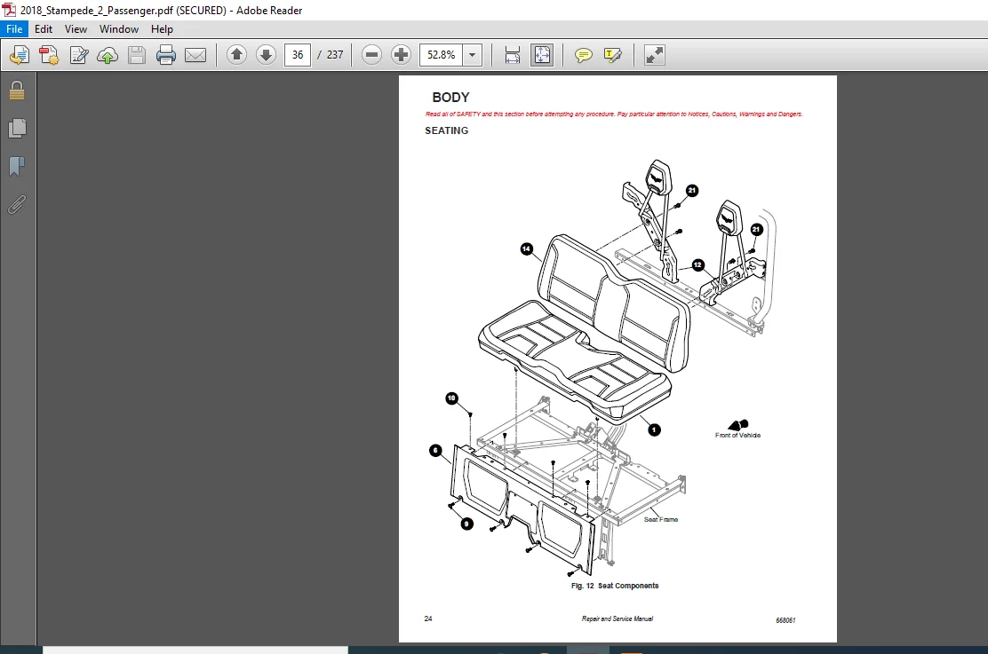
PLEASE NOTE:
- This is the same manual used by the DEALERSHIPS to SERVICE your vehicle.
- The manual can be all yours – Once payment is complete, you will be taken to the download page from where you can download the manual. All in 2-5 minutes time!!
- Need any other service / repair / parts manual, please feel free to contact us at heydownloadss @gmail.com . We may surprise you with a nice offer