
Komatsu Wa500-6 Wheel Loader Service Repair Workshop Manual Download Sn H60051 And Up – PDF DOWNLOAD
Original price was: $31.95.$19.95Current price is: $19.95.
Komatsu Wa500-6 Wheel Loader Service Repair Workshop Manual Download Sn H60051 And Up
Description
Komatsu Wa500-6 Wheel Loader Service Repair Workshop Manual Download Sn H60051 And Up
FILE DETAILS:
LANGUAGE:ENGLISH
PAGES:1767
DOWNLOADABLE:YES
FILE TYPE:PDF
KOMATSU WA500-6 WHEEL LOADER SERVICE REPAIR WORKSHOP MANUAL DOWNLOAD SN H60051 AND UP – PDF DOWNLOAD:
IMAGES PREVIEW OF THE MANUAL:
DESCRIPTION:
Komatsu Wa500-6 Wheel Loader Service Repair Workshop Manual Download Sn H60051 And Up
How to read the shop manual
1. Composition of shop manual
This shop manual contains the necessary technical information for services performed in a workshop. For ease of understanding, the manual is divided into the following sections.
00. Index and foreword
This section explains the shop manuals list, table of contents, safety, and basic information.
01. Specification
This section explains the specifications of the machine.
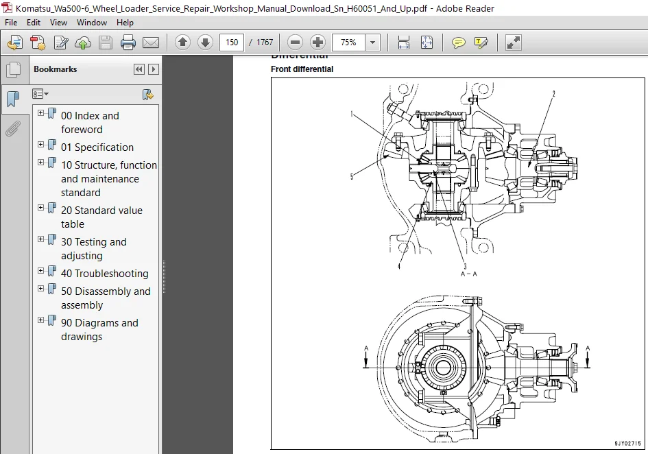
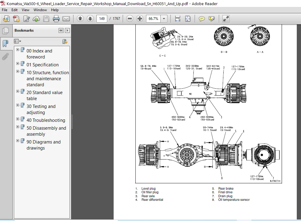
10. Structure, function and maintenance standard
This section explains the structure, function, and maintenance standard values of each component. The structure and function sub-section explains the structure and function of each component. It serves not only to give an understanding of the structure, but also serves as reference material for troubleshooting. The maintenance standard sub-section explains the criteria and remedies for disassemblyand service.
20. Standard value table
This section explains the standard values for new machine and judgement criteria for testing, adjusting, and troubleshooting. This standard value table is used to check the standard values in
testing and adjusting and to judge parts in troubleshooting.
30. Testing and adjusting
This section explains measuring instruments and measuring methods for testing and adjusting, and method of adjusting each part. The standard values and judgement criteria for testing and adjusting are explained in Testing and adjusting.
40. Troubleshooting
This section explains how to find out failed parts and how to repair them. The troubleshooting is divided by failure modes. The “S mode” of the troubleshooting related to the engine may be also
explained in the Chassis volume and Engine volume. In this case, see the Chassis volume.
50. Disassembly and assembly
This section explains the special tools and procedures for removing, installing, disassembling, and assembling each component, as well as precautions for them. In addition, tightening torque and quantity and weight of coating material, oil, grease, and coolant necessary for the work are also explained.
90. Diagrams and drawings (chassis volume)/Repair and replacement of parts (engine volume)
- q Chassis volume
This section gives hydraulic circuit diagrams and electrical circuit diagrams. - q Engine volume
This section explains the method of reproducing, repairing, and replacing parts.
TABLE OF CONTENTS:
Komatsu Wa500-6 Wheel Loader Service Repair Workshop Manual Download Sn H60051 And Up covers
00 Index and foreword.................................................................................................................................   3
	Index.............................................................................................................................................   3
		Composition of shop manual....................................................................................................................   4
		Table of contents.............................................................................................................................   6
	Foreword and general information..................................................................................................................  19
		Safety notice.................................................................................................................................  20
		How to read the shop manual...................................................................................................................  25
		Explanation of terms for maintenance standard.................................................................................................  27
		Handling of electric equipment and hydraulic component........................................................................................  29
		Handling of connectors newly used for engines.................................................................................................  38
		How to read electric wire code................................................................................................................  41
		Precautions when carrying out operation.......................................................................................................  44
		Method of disassembling and connecting push-pull type coupler.................................................................................  47
		Standard tightening torque table..............................................................................................................  50
		Conversion table..............................................................................................................................  54
01 Specification......................................................................................................................................  59
	Specification and technical data..................................................................................................................  60
		Specification dimension drawing...............................................................................................................  60
		Specifications................................................................................................................................  61
		Weight table..................................................................................................................................  64
		Table of fuel, coolant and lubricants.........................................................................................................  66
10 Structure, function and maintenance standard.......................................................................................................  67
	Engine and cooling system.........................................................................................................................  68
		Cooling system................................................................................................................................  68
		Engine mount and transmission mount...........................................................................................................  71
	Power train, Part 1...............................................................................................................................  75
		Power train...................................................................................................................................  75
		Power train system diagram....................................................................................................................  76
		Joint.........................................................................................................................................  78
		Drive shaft...................................................................................................................................  79
		Power train piping diagram....................................................................................................................  82
		Torque converter..............................................................................................................................  84
		Torque converter regulator valve.............................................................................................................. 102
		Transmission.................................................................................................................................. 104
		Transfer...................................................................................................................................... 124
		Transmission control valve.................................................................................................................... 126
		ECMV.......................................................................................................................................... 130
		Main relief valve and torque converter relief valve........................................................................................... 137
		Lubrication relief valve...................................................................................................................... 139
	Power train, Part 2............................................................................................................................... 142
		Torque converter oil cooler................................................................................................................... 142
		Torque converter oil filter................................................................................................................... 143
		Center support................................................................................................................................ 146
		Axle.......................................................................................................................................... 148
		Differential.................................................................................................................................. 150
		Limited slip differential..................................................................................................................... 159
		Final drive................................................................................................................................... 164
	Steering system................................................................................................................................... 170
		Steering piping diagram....................................................................................................................... 170
		Steering column............................................................................................................................... 171
		Steering control valve........................................................................................................................ 172
		Steering valve................................................................................................................................ 183
		Stop valve.................................................................................................................................... 187
		Joystick steering lever linkage (if equipped)................................................................................................. 188
		Steering cylinder............................................................................................................................. 189
		Emergency steering piping diagram (if equipped)............................................................................................... 190
		Diverter valve................................................................................................................................ 191
	Brake system...................................................................................................................................... 198
		Brake piping diagram.......................................................................................................................... 198
		Brake valve................................................................................................................................... 200
		Slack adjuster................................................................................................................................ 205
		Accumulator charge valve...................................................................................................................... 208
		PPC relief valve.............................................................................................................................. 212
		Accumulator (for brake)....................................................................................................................... 214
		Brake......................................................................................................................................... 216
		Parking brake control......................................................................................................................... 219
		Parking brake................................................................................................................................. 220
		Parking brake solenoid valve.................................................................................................................. 222
		Emergency parking brake release valve......................................................................................................... 224
	Undercarriage and frame........................................................................................................................... 226
		Axle mount.................................................................................................................................... 226
		Center hinge pin.............................................................................................................................. 231
	Hydraulic system, Part 1.......................................................................................................................... 236
		Hydraulic piping diagram...................................................................................................................... 236
		Work equipment control lever linkage.......................................................................................................... 238
		Hydraulic tank................................................................................................................................ 239
		Cooling fan motor............................................................................................................................. 241
		Cooling fan pump.............................................................................................................................. 248
		Steering pump................................................................................................................................. 255
		Work equipment hydraulic pump................................................................................................................. 266
	Hydraulic system, Part 2.......................................................................................................................... 286
		Control valve................................................................................................................................. 286
		CLSS.......................................................................................................................................... 300
		Each function and operation of each valve..................................................................................................... 305
		Accumulator (for PPC circuit)................................................................................................................. 316
		Work equipment electric lever................................................................................................................. 317
	Work equipment.................................................................................................................................... 322
		Work equipment linkage........................................................................................................................ 322
		Bucket........................................................................................................................................ 326
		Bucket positioner and boom kick-out........................................................................................................... 328
		Work equipment lubrication.................................................................................................................... 329
	Cab and its attachments........................................................................................................................... 332
		ROPS cab...................................................................................................................................... 332
		Air conditioner............................................................................................................................... 334
	Electrical system, Part 1......................................................................................................................... 344
		Machine monitor system........................................................................................................................ 344
		Machine monitor............................................................................................................................... 352
	Electrical system, Part 2......................................................................................................................... 406
		Work equipment control system................................................................................................................. 406
		Transmission controller system................................................................................................................ 440
	Electrical system, Part 3......................................................................................................................... 474
		Electric transmission control................................................................................................................. 474
		Engine starting circuit....................................................................................................................... 478
		Engine stopping circuit....................................................................................................................... 480
		Preheating circuit............................................................................................................................ 481
		Parking brake circuit......................................................................................................................... 483
		Backup and stop lamp circuits................................................................................................................. 488
		Small lamp and head lamp circuits............................................................................................................. 490
		Working lamp circuit.......................................................................................................................... 491
		Horn circuit.................................................................................................................................. 492
		Wiper and window washer circuits.............................................................................................................. 493
		Sensor........................................................................................................................................ 496
		KOMTRAX terminal system (if equipped)......................................................................................................... 514
20 Standard value table............................................................................................................................... 517
	Standard service value table...................................................................................................................... 518
		Standard service value table for engine....................................................................................................... 518
		Standard service value table for chassis...................................................................................................... 519
30 Testing and adjusting.............................................................................................................................. 527
	Testing and adjusting, Part 1..................................................................................................................... 529
		Tools for testing, adjusting, and troubleshooting............................................................................................. 529
		Measuring engine speed........................................................................................................................ 532
		Measuring exhaust gas color................................................................................................................... 534
		Measuring exhaust temperature................................................................................................................. 536
		Adjusting valve clearance..................................................................................................................... 538
		Testing compression pressure.................................................................................................................. 539
		Measuring blow-by pressure.................................................................................................................... 541
		Measuring engine oil pressure................................................................................................................. 542
		Measuring intake air (boost) pressure......................................................................................................... 543
		Handling fuel system equipment................................................................................................................ 545
		Releasing residual pressure in fuel system.................................................................................................... 545
		Testing fuel pressure......................................................................................................................... 546
		Testing return rate and leakage............................................................................................................... 547
		Bleeding air from fuel circuit................................................................................................................ 550
		Testing leakage in fuel system................................................................................................................ 552
		Handling reduced cylinder mode operation...................................................................................................... 553
		Handling no injection cranking operation...................................................................................................... 553
		Handling controller voltage circuit........................................................................................................... 554
		Testing and adjusting alternator belt tension................................................................................................. 555
		Testing and adjusting air conditioner compressor belt tension................................................................................. 556
		Adjusting transmission speed sensor........................................................................................................... 557
		Measuring directional lever (Steering wheel specification).................................................................................... 559
		Testing and adjusting power train oil pressure................................................................................................ 560
		Flushing procedure for torque converter and transmission hydraulic circuit.................................................................... 573
		Method of moving machine when transmission valve is broken.................................................................................... 576
	Testing and adjusting, Part 2..................................................................................................................... 581
		Testing and adjusting steering stop valve..................................................................................................... 581
		Testing and adjusting steering wheel.......................................................................................................... 583
		Testing steering oil pressure................................................................................................................. 585
		Bleeding air from steering cylinder circuit................................................................................................... 588
		Testing hydraulic drive fan................................................................................................................... 589
		Bleeding air from hydraulic drive fan circuit................................................................................................. 592
		Measuring brake pedal......................................................................................................................... 594
		Measuring brake performance................................................................................................................... 595
		Testing and adjusting accumulator charge pressure............................................................................................. 596
		Testing wheel brake oil pressure.............................................................................................................. 598
		Measuring wear of wheel brake disc............................................................................................................ 600
		Bleeding air from brake circuit............................................................................................................... 601
		Releasing residual pressure in brake accumulator circuit...................................................................................... 603
		Testing parking brake performance............................................................................................................. 604
		Measuring parking brake oil pressure.......................................................................................................... 605
		Testing wear of parking brake disc............................................................................................................ 608
		Method of releasing parking brake manually.................................................................................................... 609
		Measuring and adjusting work equipment control lever.......................................................................................... 610
		Testing and adjusting work equipment PPC oil pressure......................................................................................... 611
		Measuring work equipment oil pressure......................................................................................................... 613
		Bleeding air from work equipment circuit...................................................................................................... 619
		Releasing residual pressure in work equipment circuit......................................................................................... 620
		Method of moving machine when removing operator cab (when separate cab and floor specification)............................................... 621
		Testing and adjusting bucket positioner....................................................................................................... 622
		Testing and adjusting lift arm position detecting lever....................................................................................... 624
		Checking proximity switch operation indication lamp........................................................................................... 625
		Procedure for testing diodes.................................................................................................................. 626
		Preparations for work on troubleshooting of electrical system................................................................................. 627
	Testing and adjusting, Part 3..................................................................................................................... 632
		How to start KOMTRAX terminal operations...................................................................................................... 632
		Indicator lamps of KOMTRAX terminal........................................................................................................... 637
		Machine monitor-based adjustment at replacement, disassembly and assembly, and additional installation for each sensor and controller......... 640
		Special functions of machine monitor (EMMS)................................................................................................... 642
	Testing and adjusting, Part 4..................................................................................................................... 684
		Special functions of machine monitor (EMMS)................................................................................................... 684
		Pm clinic inspection table.................................................................................................................... 722
40 Troubleshooting.................................................................................................................................... 725
	General information on troubleshooting............................................................................................................ 726
		Points to remember when troubleshooting....................................................................................................... 726
		Sequence of events in troubleshooting......................................................................................................... 727
		Testing before troubleshooting................................................................................................................ 728
		Classification and procedures of troubleshooting.............................................................................................. 729
		Connection table for connector pin numbers.................................................................................................... 732
		T-branch box and T-branch adapter table....................................................................................................... 755
	Troubleshooting by failure code (Display of code), Part 1......................................................................................... 761
		Failure codes list............................................................................................................................ 761
		Before carrying out troubleshooting for electrical system..................................................................................... 772
		Information contained in troubleshooting table................................................................................................ 774
		Failure code [1500L0] (TORQFLOW transmission : Double meshing)................................................................................ 776
		Failure code [15B0NX] (Transmission filter: Clogged).......................................................................................... 778
		Failure code [15SAL1] (ECMV F clutch: When command current is OFF, fill signal is ON)......................................................... 780
		Failure code [15SALH] (ECMV F clutch: When command current is ON, fill signal is OFF)......................................................... 782
		Failure code [15SBL1] (ECMV R clutch: When command current is OFF, fill signal is ON)......................................................... 784
		Failure code [15SBLH] (ECMV R clutch: When command current is ON, fill signal is OFF)......................................................... 786
		Failure code [15SEL1] (ECMV 1st clutch: When command current is OFF, fill signal is ON)....................................................... 788
		Failure code [15SELH] (ECMV 1st clutch: When command current is ON, fill signal is OFF)....................................................... 790
		Failure code [15SFL1] (ECMV 2nd clutch: When command current is OFF, fill signal is ON)....................................................... 792
		Failure code [15SFLH] (ECMV 2nd clutch: When command current is ON, fill signal is OFF)....................................................... 794
		Failure code [15SGL1] (ECMV 3rd clutch: When command current is OFF, fill signal is ON)....................................................... 796
		Failure code [15SGLH] (ECMV 3rd clutch: When command current is ON, fill signal is OFF)....................................................... 798
		Failure code [15SHL1] (ECMV 4th clutch: When command current is OFF, fill signal is ON)....................................................... 800
		Failure code [15SHLH] (ECMV 4th clutch: When command current is ON, fill signal is OFF)....................................................... 802
		Failure code [2F00MA] (Parking brake: Malfunction)............................................................................................ 804
		Failure code [2G42ZG] (Front accumulator: Low oil pressure)................................................................................... 806
	Troubleshooting by failure code (Display of code), Part 2......................................................................................... 812
		Failure code [2G43ZG] (Rear accumulator: Low oil pressure).................................................................................... 812
		Failure code [44K0L4] (Bucket positioner: ON/OFF signals disagree)............................................................................ 814
		Failure code [AA1ANX] (Air cleaner: Clogging)................................................................................................. 816
		Failure code [AB00L6] (Alternator: Signal disagrees with operating state of engine)........................................................... 818
		Failure code [AB00MA] (Alternator: Malfunction)............................................................................................... 820
		Failure code [B@BAZG] (Low engine oil pressure)............................................................................................... 822
		Failure code [B@BAZK] (Engine oil: Low level)................................................................................................. 824
		Failure code [B@BCNS] (Coolant: Overheating).................................................................................................. 826
		Failure code [B@BCZK] (Coolant: Low level).................................................................................................... 828
		Failure code [B@C7NS] (Brake oil: Overheating)................................................................................................ 830
		Failure code [b@CENS] (Torque converter oil: Overheating)..................................................................................... 832
		Failure code [B@CENS] (Torque converter oil: Overheating)..................................................................................... 834
		Failure code [B@GAZK] (Battery electrolyte: Low level)........................................................................................ 836
		Failure code [B@HANS] (Hydraulic oil: Overheating)............................................................................................ 838
		Failure code [CA111] (Abnormality in engine controller)....................................................................................... 840
		Failure code [CA115] (Engine Ne or Bkup speed sensor error)................................................................................... 843
		Failure code [CA122] (Charge pressure sensor high error)...................................................................................... 844
		Failure code [CA123] (Charge pressure sensor low error)....................................................................................... 846
		Failure code [CA131] (Throttle sensor high error)............................................................................................. 847
		Failure code [CA132] (Throttle sensor low error).............................................................................................. 849
		Failure code [CA135] (Engine oil pressure sensor high error).................................................................................. 850
		Failure code [CA141] (Engine oil pressure sensor low error)................................................................................... 852
		Failure code [CA144] (Coolant temperature sensor high error).................................................................................. 853
		Failure code [CA145] (Coolant temperature sensor low error)................................................................................... 855
		Failure code [CA153] (Charge temperature sensor high error)................................................................................... 856
		Failure code [CA154] (Charge temperature sensor low error).................................................................................... 858
		Failure code [CA187] (Sensor power supply 2 low error)........................................................................................ 858
		Failure code [CA221] (Atmospheric pressure sensor high error)................................................................................. 859
		Failure code [CA222] (Atmospheric pressure sensor low error).................................................................................. 861
		Failure code [CA227] (Sensor power supply 2 high error)....................................................................................... 862
	Troubleshooting by failure code (Display of code), Part 3......................................................................................... 867
		Failure code [CA234] (Engine overspeed)....................................................................................................... 867
		Failure code [CA238] (Ne speed sensor power supply error)..................................................................................... 868
		Failure code [CA263] (Fuel temperature sensor high error)..................................................................................... 870
		Failure code [CA265] (Fuel temperature sensor low error)...................................................................................... 872
		Failure code [CA271] (PCV1 Short circuit)..................................................................................................... 874
		Failure code [CA272] (PCV1 Disconnection)..................................................................................................... 876
		Failure code [CA273] (PCV2 Short circuit)..................................................................................................... 878
		Failure code [CA274] (PCV2 Disconnection)..................................................................................................... 880
		Failure code [CA322] (Injector #1 (L/B #1) open/short error).................................................................................. 882
		Failure code [CA323] (Injector #5 (L/B #5) open/short error).................................................................................. 884
		Failure code [CA324] (Injector #3 (L/B #3) open/short error).................................................................................. 886
		Failure code [CA325] (Injector #6 (L/B #6) open/short error).................................................................................. 888
		Failure code [CA331] (Injector #2 (L/B #2) open/short error).................................................................................. 890
		Failure code [CA332] (Injector #4 (L/B #4) open/short error).................................................................................. 892
		Failure code [CA342] (Calibration code inconsistency)......................................................................................... 894
		Failure code [CA351] (Injector drive circuit error)........................................................................................... 895
		Failure code [CA352] (Sensor power supply 1 low error)........................................................................................ 898
		Failure code [CA386] (Sensor power supply 1 high error)....................................................................................... 900
		Failure code [CA431] (Idle validation switch error)........................................................................................... 902
		Failure code [CA432] (Idle validation action error)........................................................................................... 904
		Failure code [CA441] (Battery voltage low error).............................................................................................. 904
		Failure code [CA442] (Battery voltage high error)............................................................................................. 905
		Failure code [CA449] Common rail pressure high error 2........................................................................................ 905
		Failure code [CA451] (Common rail pressure sensor high error)................................................................................. 906
		Failure code [CA452] (Common rail pressure sensor low error).................................................................................. 908
		Failure code [CA553] (Common rail pressure high error 1)...................................................................................... 909
		Failure code [CA554] (Common rail pressure sensor in-range error)............................................................................. 910
		Failure code [CA559] (Supply pump pressure very low error).................................................................................... 911
		Failure code [CA689] (Engine Ne speed sensor error)........................................................................................... 914
		Failure code [CA731] (Engine Bkup speed sensor phase error)................................................................................... 916
		Failure code [CA757] (All continuous data lost error)......................................................................................... 917
		Failure code [CA778] (Engine Bkup speed sensor error)......................................................................................... 918
		Failure code [CA1228] (EGR valve servo error 1)............................................................................................... 920
		Failure code [CA1625] (EGR valve servo error 2)............................................................................................... 921
		Failure code [CA1626] (Bypass valve solenoid current high error).............................................................................. 922
		Failure code [CA1627] (Bypass valve solenoid current low error)............................................................................... 924
		Failure code [CA1628] (Bypass valve servo error 1)............................................................................................ 925
		Failure code [CA1629] (Bypass valve servo error 2)............................................................................................ 926
		Failure code [CA1631] (Bypass valve lift sensor high error)................................................................................... 928
		Failure code [CA1632] (Bypass valve lift sensor low error).................................................................................... 930
		Failure code [CA1633] (KOMNET datalink timeout error)......................................................................................... 930
	Troubleshooting by failure code (Display of code), Part 4......................................................................................... 933
		Failure code [CA1642] (EGR inlet pressure sensor low error)................................................................................... 933
		Failure code [CA1653] (EGR inlet pressure sensor high error).................................................................................. 934
		Failure code [CA2185] (Throttle sensor supply voltage high error)............................................................................. 936
		Failure code [CA2186] (Throttle sensor power supply low error)................................................................................ 938
		Failure code [CA2249] (Supply pump pressure very low error 2)................................................................................. 939
		Failure code [CA2271] (EGR valve lift sensor high error)...................................................................................... 940
		Failure code [CA2272] (EGR valve lift sensor low error)....................................................................................... 942
		Failure code [CA2351] (EGR valve solenoid operation short circuit)............................................................................ 944
		Failure code [CA2352] (EGR valve solenoid operation disconnect)............................................................................... 946
		Failure code [CA2555] (Intake heater relay disconnection error)............................................................................... 947
		Failure code [CA2556] (Intake heater relay short circuit error)............................................................................... 948
		Failure code [D160KZ] (Backup lamp relay: Disconnection or short circuit)..................................................................... 950
		Failure code [D191KA] (Joystick steering neutral safety relay: Disconnection)................................................................. 952
		Failure code [D191KB] (Joystick steering neutral safety relay: Short circuit)................................................................. 954
		Failure code [D192KA] (ECSS solenoid: Disconnection).......................................................................................... 956
		Failure code [D192KB] (ECSS solenoid: Short circuit).......................................................................................... 957
		Failure code [D192KY] (ECSS solenoid: Short circuit with power supply line)................................................................... 958
		Failure code [D193KA] (Joystick steering solenoid cut relay: Disconnection)................................................................... 960
		Failure code [D193KB] (Joystick steering solenoid cut relay: Short circuit)................................................................... 962
		Failure code [D193KY] (Joystick steering solenoid cut relay: Short circuit with power supply line)............................................ 964
		Failure code [D5ZHKA] (Terminal C signal: Disconnection)...................................................................................... 966
		Failure code [D5ZHKB] (Terminal C signal: Short circuit)...................................................................................... 968
		Failure code [D5ZHKZ] (Terminal C signal: Disconnection or short circuit)..................................................................... 970
		Failure code [D5ZHL6] (Terminal C signal: Signal does not match engine running or stopped state).............................................. 972
		Failure code [DA80L4] (Auto grease controller: ON/OFF signals disagree)....................................................................... 974
		Failure code [DAF3KK] (Machine monitor: Low source voltage (input))........................................................................... 976
		Failure code [DAF5KP] (Machine monitor: Low output voltage)................................................................................... 978
		Failure code [DAFRKR] (CAN communication with machine monitor: Defective communication (Abnormality in target component system)).............. 980
		Failure code [DAQ0KK] (Transmission controller: Low source voltage)........................................................................... 982
		Failure code [DAQ0KT] (Transmission controller: Abnormality in controller).................................................................... 984
		Failure code [DAQ2KK] (Transmission controller load power supply line: Low source voltage (input))............................................ 986
		Failure code [DAQ9KQ] (Transmission controller model selection: Disagreement of model selection signals)...................................... 988
	Troubleshooting by failure code (Display of code), Part 5......................................................................................... 992
		Failure code [DAQRKR] (CAN communication with transmission controller: Defective communication (Abnormality in target component system))...... 992
		Failure code [DAQRMA] (Transmission controller option setting: Malfunction)................................................................... 994
		Failure code [DB2RKR] (CAN communication with engine controller: Defective communication (Abnormality in target component system)............. 996
		Failure code [DB90KK] Work equipment controller: Low source voltage (input)................................................................... 998
		Failure code [DB90KT] (Work equipment controller: Abnormality in controller)..................................................................1000
		Failure code [DB92KK] Work equipment controller load power supply line: Low source voltage (input)............................................1002
		Failure code [DB95KX] (Work equipment controller power supply output: Out of input signal range)..............................................1004
		Failure code [DB99KQ] (Work equipment controller model selection: Disagreement of model selection signals)....................................1006
		Failure code [DB9RKR] (CAN communication with work equipment controller: Defective communication (Abnormality in target component system))....1008
		Failure code [DB9RMA] (Work equipment controller option setting: Malfunction).................................................................1010
		Failure code [DB9RMC] (CAN communication with work equipment controller: Defective operation).................................................1012
		Failure code [DD15LD] (t switch (Panel switch 1): Switch is kept pressed for long time).......................................................1014
		Failure code [DD16LD] (U switch (Panel switch 2): Switch is kept pressed for long time).......................................................1016
		Failure code [DD17LD] (< switch (Panel switch 3): Switch is kept pressed for long time).......................................................1018
		Failure code [DD18LD] (> switch (Panel switch 4): Switch is kept pressed for long time).......................................................1020
		Failure code [DD1ALD] (Remote positioner raise/lower set switch (raise): Switch is kept pressed for long time)................................1022
		Failure code [DD1BLD] (Remote positioner raise/lower set switch (lower): Switch is kept pressed for long time)................................1024
		Failure code [DD1CLD] (Load meter subtotal switch: Switch is kept pressed for long time)......................................................1026
		Failure code [DD1FLD] (Load meter mode selector switch (A/B): Switch is kept pressed for long time)...........................................1028
		Failure code [DD1GLD] (Load meter mode selector switch (+/-): Switch is kept pressed for long time)...........................................1030
		Failure code [DD1HLD] (Load meter display selector switch: Switch is kept pressed for long time)..............................................1032
		Failure code [DDA7L4] (RPM set ON/OFF switch: ON-OFF signals disagree)........................................................................1034
		Failure code [DDA8KB] (RPM set idle-up/down selector switch (idle-up): Short circuit).........................................................1036
		Failure code [DDA9KB] (RPM set idle-up/down selector switch (idle-down): Short circuit).......................................................1038
		Failure code [DDB6L4] (Parking brake switch (Neutralizer): ON/OFF signals disagree)...........................................................1040
	Troubleshooting by failure code (Display of code), Part 6.........................................................................................1046
		Failure code [DDD1LD] (Remote positioner bucket angle set switch: Switch is kept pressed for long time).......................................1046
		Failure code [DDE5MA] (Emergency steering drive switch: Malfunction)..........................................................................1048
		Failure code [DDK3KA] (Right FNR switch: Disconnection).......................................................................................1050
		Failure code [DDK3KB] (Right FNR switch: Short circuit).......................................................................................1052
		Failure code [DDK4KA] (Joystick steering FNR switch: Disconnection)...........................................................................1054
		Failure code [DDK4KB] (Joystick steering FNR switch: Short circuit)...........................................................................1056
		Failure code [DDK5L4] (Joystick steering shift-up/down switch: ON/OFF signals disagree).......................................................1058
		Failure code [DDK6KA] (FNR lever switch: Disconnection).......................................................................................1060
		Failure code [DDK6KB] (FNR lever switch: Short circuit).......................................................................................1064
		Failure code [DDT0L4] (Shift mode selector switch: ON/OFF signals disagree)...................................................................1066
		Failure code [DDT4LD] (Transmission cut-off set switch: Switch is kept pressed for long time).................................................1068
		Failure code [DDW9LD] (Kick-down switch: Switch is kept pressed for long time)................................................................1070
		Failure code [DDWLLD] (Hold switch: Switch is kept pressed for long time).....................................................................1072
		Failure code [DDY0LD] (Load meter cancel switch: Switch is kept pressed for long time)........................................................1074
		Failure code [DF10KA] (Transmission shift lever switch: Disconnection)........................................................................1076
		Failure code [DF10KB] (Transmission shift lever switch: Short circuit)........................................................................1080
		Failure code [DGF1KA] (Transmission oil temperature sensor: Disconnection)....................................................................1082
		Failure code [DGF1KB] (Transmission oil temperature sensor: Short circuit)....................................................................1084
		Failure code [DGH2KX] (Hydraulic oil temperature sensor: Out of input signal range)...........................................................1086
		Failure code [DGR2KA] (Rear brake oil temperature sensor: Disconnection)......................................................................1088
		Failure code [DGR2KX] (Rear brake oil temperature sensor: Out of input signal range)..........................................................1090
		Failure code [DGT1KX] (Torque converter oil temperature sensor: Out of input signal range)....................................................1092
		Failure code [DH21KA] (Work equipment pump oil pressure sensor: Disconnection)................................................................1094
	Troubleshooting by failure code (Display of code), Part 7.........................................................................................1100
		Failure code [DH21KB] (Work equipment pump oil pressure sensor: Short circuit)................................................................1100
		Failure code [DHPCKX] (Lift arm cylinder bottom pressure sensor: Out of input signal range)...................................................1102
		Failure code [DHPDKX] (Lift arm cylinder head pressure sensor: Out of input signal range).....................................................1104
		Failure code [DHT1KX] (Left brake pressure sensor: Out of input signal range).................................................................1106
		Failure code [DHT2L6] (Transmission filter clogging sensor: Signal disagrees with operating and stopped states of engine).....................1108
		Failure code [DK59KA] (Lift arm EPC lever potentiometer (Main): Disconnection)................................................................1110
		Failure code [DK59KY] (Lift arm EPC lever potentiometer (Main): Short circuit with power supply line).........................................1114
		Failure code [DK59L8] (Lift arm EPC lever potentiometer (Main): Analog signals disagree)......................................................1117
		Failure code [DK5AKA] (Lift arm EPC lever potentiometer (Sub): Disconnection).................................................................1120
		Failure code [DK5AKY] (Lift arm EPC lever potentiometer (Sub): Short circuit with power supply line)..........................................1123
		Failure code [DK5BKA] (Bucket EPC lever potentiometer (Main): Disconnection)..................................................................1126
		Failure code [DK5BKY] (Bucket EPC lever potentiometer (Main): Short circuit with power supply line)...........................................1129
		Failure code [DK5BL8] (Bucket EPC lever potentiometer (Main): Analog signals disagree)........................................................1132
		Failure code [DK5CKA] (Bucket EPC lever potentiometer (Sub): Disconnection)...................................................................1135
		Failure code [DK5CKY] (Bucket EPC lever potentiometer (Sub): Short circuit with power supply line)............................................1138
		Failure code [DK5DKA] (3-spool valve (attachment) EPC lever potentiometer (Main): Disconnection)..............................................1142
		Failure code [DK5DKY] (3-spool valve (attachment) EPC lever potentiometer (Main): Short circuit with power supply line).......................1144
		Failure code [DK5DL8] (3-spool valve (attachment) EPC lever potentiometer (Main): Analog signals disagree)....................................1146
		Failure code [DK5EKA] (3-spool valve (attachment) EPC lever potentiometer (Sub): Disconnection)...............................................1150
	Troubleshooting by failure code (Display of code), Part 8.........................................................................................1156
		Failure code [DK5EKY] (3-spool valve EPC lever potentiometer (Sub): Short circuit with power supply line).....................................1156
		Failure code [DK5FKA] (Joystick steering EPC lever potentiometer (Main): Disconnection).......................................................1158
		Failure code [DK5FKY] (Joystick steering EPC lever potentiometer (Main): Short circuit with power supply line)................................1160
		Failure code [DK5GKA] (Joystick steering EPC lever potentiometer (Sub): Disconnection)........................................................1162
		Failure code [DK5GKY] (Joystick steering EPC lever potentiometer (Sub): Short circuit with power supply line).................................1164
		Failure code [DK5FL8] (Joystick steering EPC lever potentiometer (Main): Analog signals disagree).............................................1166
		Failure code [DKA0KA] (Lift arm angle sensor: Disconnection)..................................................................................1170
		Failure code [DKA0KX] (Lift arm angle sensor: Out of input signal range)......................................................................1172
		Failure code [DKA0KY] (Lift arm angle sensor: Short circuit with power supply line)...........................................................1174
		Failure code [DKA0L0] (Lift arm angle sensor: Double meshing).................................................................................1176
		Failure code [DLF1KA] (Transmission input shaft speed sensor: Disconnection)..................................................................1178
		Failure code [DLF1LC] (Transmission input shaft speed sensor: Speed signals disagree).........................................................1180
		Failure code [DLT4KB] (Transmission output shaft speed sensor: Short circuit).................................................................1182
		Failure code [DLT4KX] (Transmission output shaft speed sensor: Out of input signal range).....................................................1184
		Failure code [DT20KB] (Transmission cut-off indicator lamp: Short circuit)....................................................................1186
		Failure code [DUM1KB] (Remote positioner raise set indicator lamp: Short circuit).............................................................1188
		Failure code [DUM2KB] (Remote positioner lower set indicator lamp: Short circuit).............................................................1190
		Failure code [DV00KB] (Alarm buzzer: Short circuit)...........................................................................................1192
		Failure code [DW4PKA] (Lift arm raise EPC solenoid: Disconnection)............................................................................1194
		Failure code [DW4PKB] (Lift arm raise EPC solenoid: Short circuit)............................................................................1195
		Failure code [DW4PKY] (Lift arm raise EPC solenoid: Short circuit with power supply line).....................................................1196
		Failure code [DW4QKA] (Lift arm lower EPC solenoid: Disconnection)............................................................................1198
		Failure code [DW4QKB] (Lift arm lower EPC solenoid: Short circuit)............................................................................1199
		Failure code [DW4QKY] (Lift arm lower EPC solenoid: Short circuit with power supply line).....................................................1200
		Failure code [DW4RKA] (Bucket tilt EPC solenoid: Disconnection)...............................................................................1202
		Failure code [DW4RKB] (Bucket tilt EPC solenoid: Short circuit)...............................................................................1204
		Failure code [DW4RKY] (Bucket tilt EPC solenoid: Short circuit with power supply line)........................................................1206
	Troubleshooting by failure code (Display of code), Part 9.........................................................................................1211
		Failure code [DW4SKA] (Bucket dump EPC solenoid: Disconnection)...............................................................................1211
		Failure code [DW4SKB] (Bucket dump EPC solenoid: Short circuit)...............................................................................1212
		Failure code [DW4SKY] (Bucket dump EPC solenoid: Short circuit with power supply line)........................................................1214
		Failure code [DW7BKA] (Fan reverse solenoid: Disconnection)...................................................................................1216
		Failure code [DW7BKB] (Fan reverse solenoid: Short circuit)...................................................................................1218
		Failure code [DW7BKY] (Fan reverse solenoid: Short circuit with power supply line)............................................................1220
		Failure code [DW7DKA] (Hydraulic drive fan neutral solenoid: Disconnection)...................................................................1222
		Failure code [DW7DKB] (Hydraulic drive fan neutral solenoid: Short circuit)...................................................................1222
		Failure code [DW7DKY] (Hydraulic drive fan neutral solenoid: Short circuit with power supply line)............................................1223
		Failure code [DWM1KA] (Work equipment neutral lock solenoid: Disconnection)...................................................................1224
		Failure code [DWM1KB] (Work equipment neutral lock solenoid: Short circuit)...................................................................1226
		Failure code [DWM1KY] (Work equipment neutral lock solenoid: Short circuit with power supply line)............................................1228
		Failure code [DWN6KA] (Lift arm raise magnet detent solenoid: Disconnection)..................................................................1230
		Failure code [DWN6KB] (Lift arm raise magnet detent solenoid: Short circuit)..................................................................1232
		Failure code [DWN6KY] (Lift arm raise magnet detent solenoid: Short circuit with power supply line)...........................................1234
		Failure code [DWN7KA] (Lift arm float magnet detent solenoid: Disconnection)..................................................................1236
		Failure code [DWN7KB] (Lift arm float magnet detent solenoid: Short circuit)..................................................................1238
		Failure code [DWN7KY] (Lift arm float magnet detent solenoid: Short circuit with power supply line)...........................................1240
		Failure code [DWN8KA] (Bucket tilt magnet detent solenoid: Disconnection).....................................................................1242
		Failure code [DWN8KB] (Bucket tilt magnet detent solenoid: Short circuit).....................................................................1244
		Failure code [DWN8KY] (Bucket tilt magnet detent solenoid: Shorted with the power source).....................................................1246
		Failure code [DX16KA] (Fan pump EPC solenoid: Disconnection)..................................................................................1248
		Failure code [DX16KB] (Fan pump EPC solenoid: Short circuit)..................................................................................1249
		Failure code [DX16KY] (Fan pump EPC solenoid: Short circuit with power supply line)...........................................................1250
		Failure code [DXA1KA] (Pump PC-EPC solenoid: Disconnection)...................................................................................1251
		Failure code [DXA1KB] (Pump PC-EPC solenoid: Short circuit)...................................................................................1252
		Failure code [DXH1KA] (Lockup ECMV solenoid: Disconnection)...................................................................................1253
		Failure code [DXH1KB] (Lockup ECMV solenoid: Short circuit)...................................................................................1254
		Failure code [DXH1KY] (Lockup ECMV solenoid: Short circuit with power supply line)............................................................1256
		Failure code [DXH4KA] (1st clutch ECMV solenoid: Disconnection)...............................................................................1258
		Failure code [DXH4KB] (1st clutch ECMV solenoid: Short circuit)...............................................................................1260
	Troubleshooting by failure code (Display of code), Part 10........................................................................................1266
		Failure code [DXH4KY] (1st clutch ECMV solenoid: Short circuit with power supply line)........................................................1266
		Failure code [DXH5KA] (2nd clutch ECMV solenoid: Disconnection)...............................................................................1268
		Failure code [DXH5KB] (2nd clutch ECMV solenoid: Short circuit)...............................................................................1270
		Failure code [DXH5KY] (2nd clutch ECMV solenoid: Short circuit with power supply line)........................................................1272
		Failure code [DXH6KA] (3rd clutch ECMV solenoid: Disconnection)...............................................................................1274
		Failure code [DXH6KB] (3rd clutch ECMV solenoid: Short circuit)...............................................................................1276
		Failure code [DXH6KY] (3rd clutch ECMV solenoid: Short circuit with power supply line)........................................................1278
		Failure code [DXH7KA] (R clutch ECMV solenoid: Disconnection).................................................................................1280
		Failure code [DXH7KB] (R clutch ECMV solenoid: Short circuit).................................................................................1282
		Failure code [DXH7KY] (R clutch ECMV solenoid: Short circuit with power supply line)..........................................................1284
		Failure code [DXH8KA] (F clutch ECMV solenoid: Disconnection).................................................................................1286
		Failure code [DXH8KB] (F clutch ECMV solenoid: Short circuit).................................................................................1288
		Failure code [DXH8KY] (F clutch ECMV solenoid: Short circuit with power supply line)..........................................................1290
		Failure code [DXHHKA] (4th clutch ECMV solenoid: Disconnection)...............................................................................1292
		Failure code [DXHHKB] (4th clutch ECMV solenoid: Short circuit)...............................................................................1294
		Failure code [DXHHKY] (4th clutch ECMV solenoid: Short circuit with power supply line)........................................................1296
		Failure code [DXHJKA] (3-spool valve extract EPC solenoid: Disconnection).....................................................................1298
		Failure code [DXHJKB] (3-spool valve extract EPC solenoid: Short circuit).....................................................................1299
		Failure code [DXHJKY] (3-spool valve extract EPC solenoid: Short circuit with power supply line)..............................................1300
		Failure code [DXHKKA] (3-spool valve retract EPC solenoid: Disconnection).....................................................................1301
		Failure code [DXHKKB] (3-spool valve retract EPC solenoid: Short circuit).....................................................................1302
		Failure code [DXHKKY] (3-spool valve retract EPC solenoid: Short circuit with power supply line)..............................................1303
		Failure code [DXHLKA] (Joystick steering right EPC solenoid: Disconnection)...................................................................1304
		Failure code [DXHLKB] (Joystick steering right EPC solenoid: Short circuit)...................................................................1306
		Failure code [DXHLKY] (Joystick steering right EPC solenoid: Short circuit with power supply line)............................................1308
		Failure code [DXHMKA] (Joystick steering left EPC solenoid: Disconnection)....................................................................1310
		Failure code [DXHMKB] (Joystick steering left EPC solenoid: Short circuit)....................................................................1312
		Failure code [DXHMKY] (Joystick steering left EPC solenoid: Short circuit with power supply line).............................................1314
	Troubleshooting of electrical system (E-mode).....................................................................................................1319
		Before carrying out troubleshooting of electrical system......................................................................................1319
		Information in troubleshooting table..........................................................................................................1322
		E-1 Engine does not start.....................................................................................................................1323
		E-2 Wiper does not operate....................................................................................................................1328
		E-3 Windshield washer does not operate........................................................................................................1332
		E-4 Headlamp, clearance lamp, tail lamp, and license lamp do not light up or go off...........................................................1335
		E-5 Working lamp does not light up or go off..................................................................................................1343
		E-6 Turn signal lamp and hazard lamp do not light up or go off................................................................................1348
		E-7 Brake lamp does not light or it keeps lighting up.........................................................................................1354
		E-8 Backup lamp does not light or it keeps lighting up........................................................................................1356
		E-9 Backup buzzer does not sound or it keeps sounding.........................................................................................1358
		E-10 Horn does not sound or it keeps sounding.................................................................................................1360
		E-11 Alarm buzzer does not sound or it keeps sounding.........................................................................................1364
		E-12 Air conditioner does not operate or stop.................................................................................................1366
		E-13 KOMTRAX system does not work properly....................................................................................................1370
	Troubleshooting of hydraulic and mechanical system (H-mode).......................................................................................1375
		Method of using troubleshooting chart.........................................................................................................1375
		Table of failure modes and causes.............................................................................................................1378
		H-1 Machine does not start....................................................................................................................1382
		H-2 Torque converter lockup is not switched off (engine stalls) [Machine with lockup clutch (if equipped)]....................................1384
		H-3 Torque converter lockup is not switched ON [Machine with lockup clutch (if equipped)].....................................................1385
		H-4 Travel speed is slow, thrusting force is weak, uphill traveling power is weak, and gear is not shifted....................................1386
		H-5 Shocks are large at the times of starting and shifting gear...............................................................................1388
		H-6 Time lag is large at the times of starting and shifting gear..............................................................................1390
		H-7 Torque converter oil temperature is high..................................................................................................1392
		H-8 Steering does not turn....................................................................................................................1393
		H-9 Steering does not turn [Machine with joystick steering (if equipped)].....................................................................1394
		H-10 Steering response is low.................................................................................................................1395
		H-11 Turning response of steering is poor [machine with joystick steering (if equipped)]......................................................1396
		H-12 Steering is heavy........................................................................................................................1397
		H-13 When machine turns, it shakes or makes large shocks......................................................................................1398
		H-14 When machine turns, it shakes or makes large shocks [machine with joystick steering (if equipped)].......................................1399
		H-15 Wheel brake does not work or does not work well..........................................................................................1400
		H-16 Wheel brake is not released or it drags..................................................................................................1401
		H-17 Parking brake does not work or does not work well........................................................................................1402
		H-18 Parking brake is not released or it drags (including emergency release system)...........................................................1403
		H-19 Lift arm does not rise...................................................................................................................1404
		H-20 Lift arm speed is low or rising force of lift arm is insufficient........................................................................1405
		H-21 When rising, lift arm comes to move slowly at specific height............................................................................1406
		H-22 Lift arm cylinder cannot hold down bucket (Bucket floats)................................................................................1406
		H-23 Hydraulic drifts of lift arm occur often.................................................................................................1406
		H-24 Lift arm wobbles during operation........................................................................................................1406
		H-25 Bucket does not tilt back................................................................................................................1407
		H-26 Bucket speed is low or tilting back force is insufficient................................................................................1408
		H-27 Bucket comes to operate slowly in the midst of tilting-back..............................................................................1409
		H-28 Bucket cylinder cannot hold down the bucket..............................................................................................1409
		H-29 Hydraulic drifts of bucket occur often...................................................................................................1409
		H-30 Bucket wobbles during travel with cargo (Work equipment valve is set to “HOLD”)..........................................................1409
		H-31 During operation of machine, engine speed lowers remarkably or engine stalls.............................................................1410
		H-32 Large shocks are made when work equipment starts and stops...............................................................................1410
		H-33 When work equipment circuit is relieved singly, other work equipment moves...............................................................1410
		H-34 ECSS does not operate, and pitching and bouncing occur...................................................................................1411
	Troubleshooting of engine (S-mode)................................................................................................................1415
		Method of using troubleshooting chart.........................................................................................................1415
		S-1 Engine does not start easily..............................................................................................................1418
		S-2 Engine does not start.....................................................................................................................1420
		S-3 Engine does not pick up smoothly..........................................................................................................1424
		S-4 Engine stops during operation.............................................................................................................1425
		S-5 Engine does not rotate smoothly (Engine hunts.)...........................................................................................1426
		S-6 Engine lacks output (or lacks power)......................................................................................................1427
		S-7 Exhaust smoke is black (Incomplete combustion)............................................................................................1428
		S-8 Oil is consumed much (or exhaust gas color is blue).......................................................................................1430
		S-9 Engine oil becomes contaminated quickly...................................................................................................1431
		S-10 Fuel consumption is excessive............................................................................................................1432
		S-11 Coolant contains oil (blows back or reduces).............................................................................................1433
		S-12 Oil pressure drops.......................................................................................................................1434
		S-13 Oil level rises (Water, fuel in oil).....................................................................................................1435
		S-14 Coolant temperature rises too high (Overheating).........................................................................................1437
		S-15 Abnormal noise is made...................................................................................................................1438
		S-16 Vibration is excessive...................................................................................................................1439
50 Disassembly and assembly...........................................................................................................................1441
	General information on disassembly and assembly...................................................................................................1441
		How to read this manual.......................................................................................................................1442
		Coating materials list........................................................................................................................1444
		Special tool list.............................................................................................................................1447
		Sketches of special tools.....................................................................................................................1451
	Engine and cooling system.........................................................................................................................1457
		Removal and installation of engine assembly...................................................................................................1458
		Removal and installation of radiator assembly.................................................................................................1463
		Removal and installation of air aftercooler...................................................................................................1465
		Removal and installation of cooling fan and fan motor assembly................................................................................1466
		Removal and installation of radiator guard and cooling fan motor assembly.....................................................................1468
		Removal and installation of fuel tank assembly................................................................................................1471
		Removal and installation of hood..............................................................................................................1473
	Engine (SAA6D140E-5)..............................................................................................................................1477
		Removal and installation of fuel supply pump assembly.........................................................................................1478
		Removal and installation of cylinder head assembly............................................................................................1482
		Removal and installation of fuel injector assembly............................................................................................1493
		Removal and installation of engine front seal.................................................................................................1496
		Removal and installation of engine rear seal..................................................................................................1500
	Power train, Part 1...............................................................................................................................1505
		Removal and installation of torque converter and transmission assembly........................................................................1506
		Disconnection and connection of power train unit..............................................................................................1512
		Disassembly and assembly of input transfer assembly...........................................................................................1516
		Disassembly and assembly of torque converter assembly (Lockup specification)..................................................................1523
		Disassembly and assembly of torque converter assembly (Lockup-less specification).............................................................1536
	Power train, Part 2...............................................................................................................................1547
		Disassembly and assembly of transmission assembly.............................................................................................1548
		Disassembly and assembly of transfer and parking brake assembly...............................................................................1578
		Removal and installation of front axle assembly...............................................................................................1594
		Removal and installation of rear axle assembly................................................................................................1596
	Power train, Part 3...............................................................................................................................1599
		Removal and installation of front differential assembly.......................................................................................1600
		Disassembly and assembly of differential assembly (LSD specification).........................................................................1602
		Disassembly and assembly of differential assembly (LSD-less specification)....................................................................1616
		Disassembly and assembly of final drive assembly (Front and rear).............................................................................1627
	Brake system......................................................................................................................................1636
		Removal and installation of brake assembly (Front and rear)...................................................................................1636
		Disassembly and assembly of brake assembly (Front and rear)...................................................................................1638
		Disassembly and assembly of slack adjuster assembly...........................................................................................1644
		Disassembly and assembly of brake accumulator charge valve assembly...........................................................................1645
	Removal and installation of center hinge pin......................................................................................................1648
	Hydraulic system..................................................................................................................................1655
		Removal and installation of hydraulic tank assembly...........................................................................................1656
		Removal and installation of cooling pump assembly.............................................................................................1659
		Removal and installation of fan pump assembly.................................................................................................1660
		Removal and installation of work equipment pump assembly......................................................................................1661
		Removal and installation of steering, torque converter charge and EPC pump assembly...........................................................1663
		Removal and installation of work equipment valve assembly.....................................................................................1664
		Disassembly and assembly of work equipment control valve assembly.............................................................................1667
		Disassembly and assembly of steering cylinder assembly........................................................................................1670
		Disassembly and assembly of lift arm and/bucket cylinder assembly.............................................................................1674
		Removal and installation of steering valve assembly...........................................................................................1680
	Work equipment....................................................................................................................................1681
		Removal and installation of work equipment assembly...........................................................................................1682
		Removal and installation of large counterweight assembly......................................................................................1686
		Removal and installation of small counterweight assembly......................................................................................1687
	Cab and its attachments...........................................................................................................................1689
		Removal and installation of operator's cab assembly (Separate cab and floor specification)....................................................1690
		Removal and installation of operator's cab and floor frame assembly (Cab-floor unit specification)............................................1695
		Removal and installation of operator's cab glass (Stuck glass)................................................................................1699
		Disassembly and assembly of operator’s seat assembly..........................................................................................1708
	Electrical system.................................................................................................................................1741
		Removal and installation of engine controller assembly........................................................................................1742
		Removal and installation of transmission controller assembly..................................................................................1743
		Removal and installation of work equipment controller assembly................................................................................1744
		Removal and installation of air conditioner unit assembly.....................................................................................1745
90 Diagrams and drawings..............................................................................................................................1749
	Hydraulic diagrams and drawings...................................................................................................................1749
		Power train hydraulic circuit diagram.........................................................................................................1751
		Brake hydraulic circuit diagram...............................................................................................................1753
		Work equipment hydraulic circuit diagram......................................................................................................1755
	Electrical diagrams and drawings..................................................................................................................1756
		Air conditioner electrical circuit diagram....................................................................................................1758
		Electrical circuit diagram (1/7)..............................................................................................................1759
		Electrical circuit diagram (2/7)..............................................................................................................1760
		Electrical circuit diagram (3/7)..............................................................................................................1761
		Electrical circuit diagram (4/7)..............................................................................................................1762
		Electrical circuit diagram (5/7)..............................................................................................................1763
		Electrical circuit diagram (6/7)..............................................................................................................1764
		Electrical circuit diagram (7/7)..............................................................................................................1765
	Connector arrangement diagram.....................................................................................................................1766
PLEASE NOTE:
- This is the SAME exact manual used by your dealers to fix your vehicle.
- The same can be yours in the next 2-3 mins as you will be directed to the download page immediately after paying for the manual.
- Any queries / doubts regarding your purchase, please feel free to contact [email protected]


