
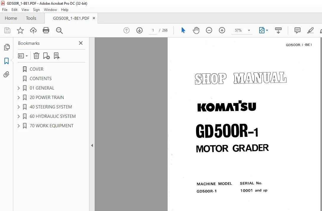
KOMATSU GD500R-1 MOTOR GRADER Shop Manual GD500R.1 -BE1 – PDF
$28.95
KOMATSU GD500R-1 MOTOR GRADER Shop Manual GD500R.1 -BE1 – PDF DOWNLOAD
GD500R-1
10001 and up
Description
KOMATSU GD500R-1 MOTOR GRADER Shop Manual GD500R.1 -BE1 – PDF DOWNLOAD
FILE DETAILS:
KOMATSU GD500R-1 MOTOR GRADER Shop Manual GD500R.1 -BE1 – PDF DOWNLOAD
Language : English
Pages :266
Downloadable : Yes
File Type : PDF
DESCRIPTION:
KOMATSU GD500R-1 MOTOR GRADER Shop Manual GD500R.1 -BE1 – PDF DOWNLOAD
GD500R-1
10001 and up
FOREWORD
- Only through correct operation, maintenance, trouble shooting, and repairs, can the effective performance, prevention of breakdowns and a long useful life of a machine be sustained.
- The object of this “Shop Manual” is to furnish the information needed by the serviceman to perform his work well, by giving him the essential details precisely but in an easily understood format. In performing his work, the serviceman should study the pertinent section of this manual carefully, and work systematically and scientifically by following the outlined work sequence.
- This Shop Manual has been prepared with the above in mind, so that each basic part of the machine is dealt with under the headings: “Construction and Function”, “Testing and Adjustments”, “Trouble shoot ing”, “Specifications” and “Disassembly and Assembly”. Also a section on General Technical Procedures is provided to furnish details on basic operations and procedures common to the serviceman’s work on the different parts of the machine.
1. General Instructions
This section presents under one heading the basic information and procedures common to the sections on “Disassembly and Assembly”, “Testing and Adjustments”, “Trouble shooting”, and “Dismounting and Mounting”. It is essential for the serviceman to thoroughly understand and know this section till it becomes a part of his common sense.
2. Construction and Function.
This section gives a detailed explanation of the “Construction” with details and drawings of the “Constituent Parts” and “block” or “circuit” diagrams, arranged for the serviceman, but also useful as a textbook for training service personnel. However, in the latter case Training Aids should be used to cover the basic theory not included in this manual.
3. Testing and Adjustments.
Procedures of all the necessary “Tests” and “Adjustments” are described with photographs showing the necessary measuring equipment and the location for making the measurements. This should aid the serviceman in his trouble shooting, checking and adjusting work.
4. Trouble Shooting
Typical common troubles are listed and systematically described; with their causes and the procedures for finding and diagnosing the symptoms. As it is impossible to list all of the possible troubles, the serviceman should study the sections covering the “Construction and Function” and “Testing and Adjustments” and apply this knowledge to diagnose any non-listed troubles.
5. Specifications
In this section, all standard dimensions and tolerances that are necessary to perform Testing and Adjustments are presented; with drawings together with, appropriate procedures for disassembly and assembly, performing repairs, or trouble shooting. However, basic dimensions and tolerances, for repairs or rebuilding, are limited to those machine parts most commonly
worked on.
TABLE OF CONTENTS:
KOMATSU GD500R-1 MOTOR GRADER Shop Manual GD500R.1 -BE1 – PDF DOWNLOAD
COVER 1
CONTENTS 6
01 GENERAL 7
GENERAL 8
GENERAL LOCATIONS 9
SPECIFICATIONS 11
ENGINE PERFORMANCE CURVE 12
WEIGHT TABLE 13
POWER TRANSMITTING SYSTEM 14
20 POWER TRAIN 16
21 STRUCTURE AND FUNCTION 16
STRUCTURE AND FUNCTION 17
CLUTCH 18
CLUTCH BOOSTER 19
TRANSMISSION 22
FINAL DRIVE 26
TANDEM DRIVE 28
22 TESTING AND ADJUSTING 30
TESTING AND ADJUSTING 31
ADJUSTING CLUTCH 32
23 DISASSEMBLY AND ASSEMBLY 33
DISASSEMBLY AND ASSEMBLY 34
DISMOUNTING POWER TRAIN 35
MOUNTING POWER TRAIN 37
DISMOUNTING ENGINE 39
MOUNTING ENGINE 42
DISASSEMBLY OF CLUTCH 44
ASSEMBLY OF CLUTCH 48
DISASSEMBLY OF CLUTCH BOOSTER 58
ASSEMBLY OF CLUTCH BOOSTER 60
DISASSEMBLY OF CLUTCH BOOSTER ASSEMBLY 61
ASSEMBLY OF CLUTCH BOOSTER ASSEMBLY 63
DISMOUNTING TRANSMISSION 71
MOUNTING TRANSMISSION 74
DISASSEMBLY OF TRANSMISSION 76
ASSEMBLY OF TRANSMISSION 86
DISASSEMBLY OF REAR AXLE102
ASSEMBLY OF REAR AXLE104
DISMOUNTING TANDEM DRIVE112
MOUNTING TANDEM DRIVE115
DISASSEMBLY OF TANDEM DRIVE118
ASSEMBLY OF TANDEM DRIVE121
24 MAINTENANCE STANDARD125
MAINTENANCE STANDARD126
CLUTCH127
CLUTCH BOOSTER129
TRANSMISSION131
TANDEM DRIVE133
40 STEERING SYSTEM134
41 STRUCTURE AND FUNCTION134
STRUCTURE AND FUNCTION135
STEERING SYSTEM136
STEERING BOOSTER137
FUNCTION OF STEERING BOOSTER138
STEERING GEAR140
FRONT AXLE141
WHEEL146
BRAKE148
PARKING BRAKE150
42 TESTING AND ADJUSTING152
TESTING AND ADJUSTING153
CHECKING AND ADJUSTING FRONT WHEEL BEARING PLAY154
CHECK THE RETIGHTENING OF WHEEL HUB NUTS154
CHECKING AND ADJUSTING FOOT BRAKE155
CHECKING AND ADJUSTING PARKING BRAKE156
CHECKING AND ADJUSTING TOE-IN156
CHECKING TIE-ROD FOR WEAR OR LOOSENING158
CHECKING AND ADJUSTING PLAY OF STEERING WHEEL158
43 DISASSEMBLY AND ASSEMBLY159
DISASSEMBLY AND ASSEMBLY160
DISMOUNTING FRONT AXLE161
MOUNTING FRONT AXLE163
DISASSEMBLY OF FRONT AXLE164
ASSEMBLY OF FRONT AXLE167
DISMOUNTING WHEEL170
MOUNTING WHEEL171
DISASSEMBLY OF WHEEL172
ASSEMBLY OF WHEEL173
DISMOUNTING WHEEL BRAKE174
MOUNTING WHEEL BRAKE175
DISASSEMBLY OF WHEEL BRAKE176
ASSEMBLY OF WHEEL BRAKE179
DISASSEMBLY AND ASSEMBLY OF MASTER CYLINDER181
DISMOUNTING AND MOUNTING STEERING GEAR183
DISASSEMBLY OF STEERING GEAR185
ASSEMBLY OF STEERING GEAR188
DISMOUNTING STEERING BOOSTER191
MOUNTING STEERING BOOSTER192
DISASSEMBLY OF STEERING BOOSTER193
ASSEMBLY OF STEERING BOOSTER198
44 MAINTENANCE STANDARD203
MAINTENANCE STANDARD204
STEERING HANDLE205
FRONT AXLE206
TIE ROD207
PARKING BRAKE208
SERVICE BRAKE209
60 HYDRAULIC SYSTEM210
61 STRUCTURE AND FUNCTION210
STRUCTURE AND FUNCTION211
HYDRAULIC CONTROL212
PIPING DIAGRAM214
HYDRAULIC CONTROL VALVE216
RELIEF VALVE OPERATION219
CONTROL VALVE OPERATION220
HYDRAULIC CYLINDER222
FLOW DIVIDER225
PILOT CHECK VALVE228
SLOW RETURN VALVE229
HYDRAULIC PUMP230
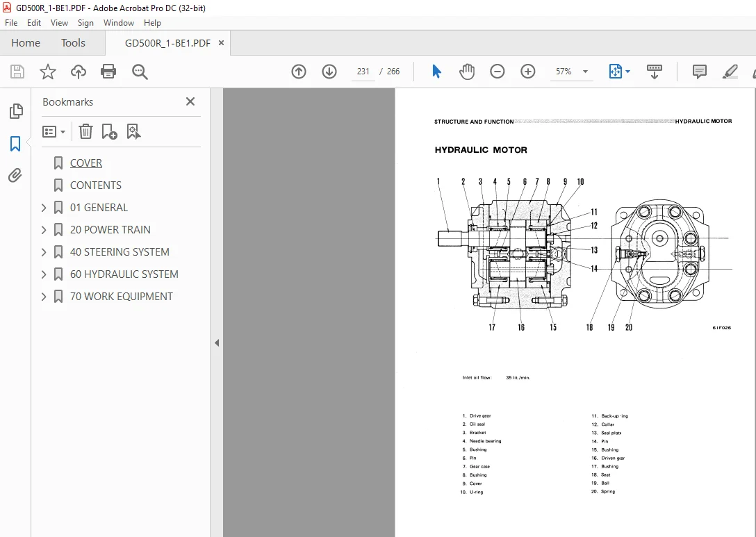
HYDRAULIC MOTOR231
62 TESTING AND ADJUSTING232
TESTING AND ADJUSTING233
GENERAL234
OIL PRESSURE TEST GUIDE235
64 MAINTENANCE STANDARD236
MAINTENANCE STANDARD237
HYDRAULIC CONTROL VALVE238
HYDRAULIC CYLINDER239
70 WORK EQUIPMENT242
71 STRUCTURE AND FUNCTION242
STRUCTURE AND FUNCTION243
BLADE244
WORK EQUIPMENT CONTROL LEVEL245
CIRCLE REVERSE GEAR246
SCARIFIER(OPTION)247
72 TESTING AND ADJUSTING248
TESTING AND ADJUSTING249
CHECKING AND ADJUSTING BALL JOINT CLEARANCE250
ADJUSTING BLADE CUTTING ANGLE250
CHECKING AND ADJUSTING CIRCLE GUIDE BLOCK CLEARANCE251
CHECKING DRAWBAR FRONT BALL JOINT FOR LOOSENING251
ADJUSTING SCARIFIER CUTTING ANGLE AND DEPTH252
73 DISASSEMBLY AND ASSEMBLY253
DISASSEMBLY AND ASSEMBLY254
DISMOUNTING BLADE CIRCLE REVERSE GEAR255
MOUNTING BLADE CIRCLE REVERSE GEAR256
DISASSEMBLY OF BLADE CIRCLE REVERSE GEAR257
ASSEMBLY OF BLADE CIRCLE REVERSE GEAR260
74 MAINTENANCE STANDARD262
MAINTENANCE STANDARD263
CIRCLE REVERSE GEAR264
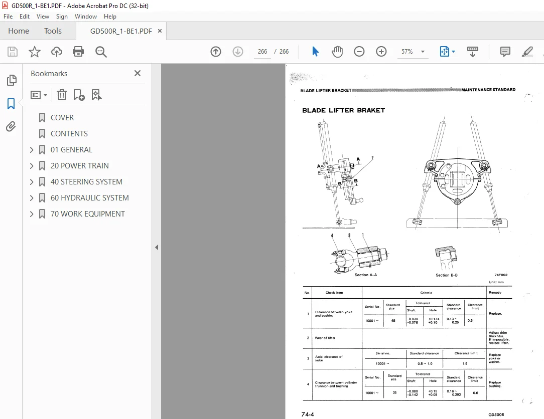
BLADE LIFTER BRACKET266
IMAGES PREVIEW OF THE MANUAL:
S.M 16/12/24



