Acer Extensa 2000 2500 Series Service Guide Manual – PDF DOWNLOAD
Acer Extensa 2000 2500 Series Service Guide Manual – PDF DOWNLOADPreface Before using this information and the product it supports, please read the following general information. 1. This Service Guide provides you with all technical information relating to the BASIC CONFIGURATION decided for Acer’s “global” product offering. To better fit local market requirements and enhance product competitiveness, your regional office MAY have decided to extend the functionality of a machine (e.g. add-on card, modem, or extra memory capability). These LOCALIZED FEATURES will NOT be covered in this generic service guide. In such cases, please contact your regional offices or the responsible personnel/channel to provide you with further technical details. 2. Please note WHEN ORDERING FRU PARTS, that you should check the most up-to-date information available on your regional web or channel. If, for whatever reason, a part number change is made, it will not be noted in the printed Service Guide. For ACER-AUTHORIZED SERVICE PROVIDERS, your Acer office may have a DIFFERENT part number code to those given in the FRU list of this printed Service Guide. You MUST use the list provided by your regional Acer office to order FRU parts for repair and service of customer machines
Acer Extensa 2000 2500 Series Service Guide Manual – PDF DOWNLOAD
Acer Extensa 2000_2500 Series.................................. 1
Revision History........................................... 2
Copyright.................................................. 3
Disclaimer................................................. 3
Conventions................................................ 4
Preface.................................................... 5
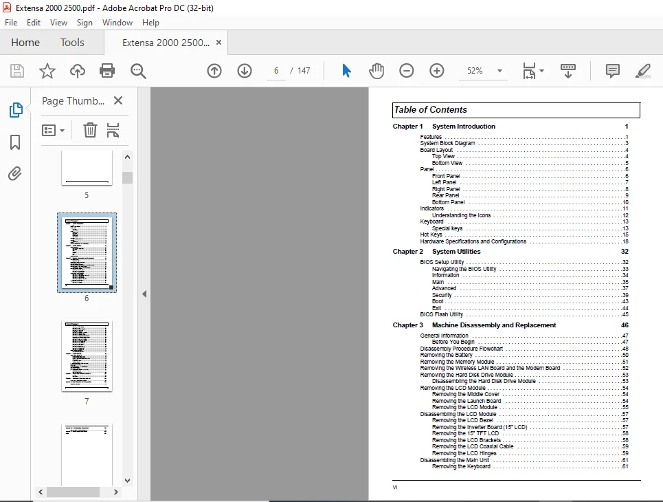
Table of Contents.......................................... 6
Ch.1 System Introduction................................... 10
Features............................................... 10
System Block Diagram................................... 12
Board Layout........................................... 13
Top View........................................... 13
Bottom View........................................ 14
Panel.................................................. 15
Front Panel........................................ 15
Left Panel......................................... 16
Right Panel........................................ 17
Rear Panel......................................... 18
Bottom Panel....................................... 19
Indicators............................................. 20
Understanding the icons............................ 21
Keyboard............................................... 22
Special keys....................................... 22
Hot Keys............................................... 24
Hardware Specifications and Configurations............. 27
Ch.2 System Utilities...................................... 41
BIOS Setup Utility..................................... 41
Navigating the BIOS Utility........................ 42
Information........................................ 43
Main............................................... 44
Advanced........................................... 46
Security........................................... 48
Boot............................................... 52
Exit............................................... 53
BIOS Flash Utility..................................... 54
Ch.3 Machine Disassembly and Replacement................... 55
General Information.................................... 56
Before You Begin................................... 56
Disassembly Procedure Flowchart........................ 57
Removing the Battery................................... 59
Removing the Memory Module............................. 60
Removing the Wireless LAN Board and the Modem Board.... 61
Removing the Hard Disk Drive Module.................... 62
Disassembling the Hard Disk Drive Module........... 62
Removing the LCD Module................................ 63
Removing the Middle Cover.......................... 63
Removing the Launch Board.......................... 63
Removing the LCD Module............................ 64
Disassembling the LCD Module........................... 66
Removing the LCD Bezel............................. 66
Removing the Inverter Board (15” LCD).............. 66
Removing the 15” TFT LCD........................... 67
Removing the LCD Brackets.......................... 67
Removing the LCD Coaxial Cable..................... 68
Removing the LCD Hinges............................ 68
Disassembling the Main Unit............................ 70
Removing the Keyboard.............................. 70
Removing the RTC Battery........................... 70
Removing the Fan................................... 70
Removing the Thermal Module........................ 71
Removing the Processor............................. 71
Installing the Processor........................... 72
Removing the Upper Case Assemly.................... 72
Removing the Touchpad Board........................ 73
Removing the Touchpad Cable........................ 73
Removing the Floppy Disk Drive Module.............. 74
Dissembling the Floppy Disk Drive Module........... 74
Removing the VGA Thermal Plate..................... 75
Removing the CPU Heatsink Plate.................... 75
Removing the Second Fan Bracket.................... 76
Removing the ODD Module(1)......................... 76
Removing the ODD Module(2)......................... 76
Removing the HDD Bracket........................... 77
Removing the Main Board............................ 77
Removing the DC Board.............................. 78
Removing the I/O Port Bracket...................... 78
Removing the PCMCIA Slot........................... 79
Removing the Speaker Set........................... 80
System Upgrade Procedure............................... 81
Base Unit to Wireless Unit......................... 81
Ch.4 Troubleshooting....................................... 83
System Check Procedures................................ 84
External Diskette Drive Check...................... 84
External CD-ROM Drive Check........................ 84
Keyboard or Auxiliary Input Device Check........... 84
Memory check....................................... 85
Power System Check................................. 85
Touchpad Check..................................... 87
Power-On Self-Test (POST) Error Message................ 88
Index of Error Messages................................ 89
POST Code.............................................. 92
Index of Symptom-to-FRU Error Message.................. 96
Intermittent Problems.................................. 99
Undetermined Problems..................................100
How to Build NAPP Master Hard Disc Drive...............101
CD to Disk Recovery................................101
Disk to Disk Recovery..............................104
Ch.5 Jumper and Connector Locations........................109
Top View...............................................109
Bottom View............................................111
Ch.6 FRU (Field Replaceable Unit) List.....................113
Extensa 2000/2500 Exploded Diagram.....................114
App.A Model Definition and Configuration...................135
Model Name Definition..................................135
App.B Test Compatible Components...........................137
Microsoft(R)Windows(R)XP Environment Test..............138
App.C Online Support Information...........................143
PLEASE NOTE:
This is not a physical manual but a digital manual – meaning no physical copy will be couriered to you. The manual can be yours in the next 2 mins as once you make the payment, you will be directed to the download page IMMEDIATELY.
This is the same manual used by the dealers inorder to diagnose your vehicle of its faults.
Require some other service manual or have any queries: please WRITE to us at [email protected]
s.m
✹
What Our Customers Say
★★★★★Live reviews from customers
Loading customer reviews...
🌟 Related Products
Discover more professional manuals for your equipment