Aichi SR-210 SERVICE MANUAL SME-113 A – PDF DOWNLOAD
Original price was: $84.95.$21.95Current price is: $21.95.
Aichi SR-210 SERVICE MANUAL SME-113 A – PDF DOWNLOAD
Description
Aichi SR-210 SERVICE MANUAL SME-113 A – PDF DOWNLOAD
IMAGES PREVIEW OF THE MANUAL:
DESCRIPTION:
Aichi SR-210 SERVICE MANUAL SME-113 A – PDF DOWNLOAD
This manual describes correct adjustment and servicing
procedures for SR-210 self-propelled aerial platform
in order to ensure the most effective use of superb
performance and excellent operation features for your
satisfaction.
Read this manual carefully and understand the descriptions
correctly.
Always make sure the following items when maintenance
or repair work is carried out.
• Use only the spare parts approved by manufacturer,
particularly for load-supporting and safety-related
components.
• Do not carry out any modification to the machine
without obtaining manufacturer’s approval.
Please note that the numerical values in this manual
may be subject to change due to engineering improvement.
TABLE OF CONTENTS:
Aichi SR-210 SERVICE MANUAL SME-113 A – PDF DOWNLOAD
GENERAL INFORMATION
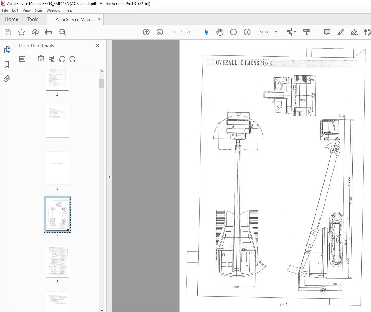
OVERALL DIMENSIONS
SPECIFICATIONS
WORK I NG RANGE CHART
MECHANICAL SECTION
BOOM
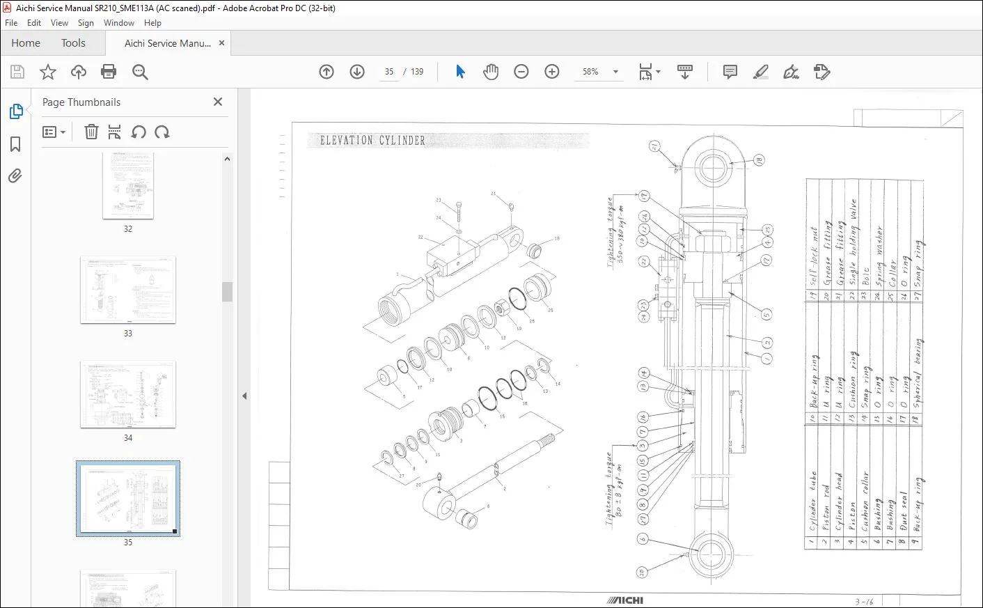
1 Sectional d r awings
2 Inspect ion procedures
T T B (Turn Tab 1 e Be a r in g )
PLATFORM SWING MECHANIS~
HYDRAULIC SECTI ON
NOTE ON OVERHAULING HYDRAULIC SYSTEM
HYDRAULIC OIL
0 I L R E S E RV O I R
I N – L I NE F I LT ER
HYDRAULIC PUMP
MAIN CONTROL VALVE NO 1 and NO 2
1 Illustrations
2 Sectional drawings
3 Trouble shooting
PLATFORM SWING SOLENOID VALVE
PRIORITY VALVE
SWIVEL JOINT
ROTATION MOTOR UNIT
ELEV AT ION CY L IND ER
SINGLE HOLDING VALVE
(for Elevation c yl i nder )
Inspection procedures
EX T ENSION CYLINDER
DOUBLE HOLDING VALVE
(fo r Extension cylinder)
Inspection p r ocedures
P L AT F O RM L E V E L L I N G S Y S T E M
1 No t e o n f u n c t i on
2 Inspection procedures
3 Adjustment of Platform level
LOWER LEVELL I NG CYLINDER
UPPER LEVELL ING CY L IND ER
DOUBLE PILOT CHECK VALVE
(for Upper levelling cylinder )
CONBINAT I ON VALVE
( f o r P 1 a t f o r m 1 e v e 1 1 i n g s y s t e m)
ELECTRIC SECTION
UPPER CONTROL BOX
EI e ctr i c c i r cu i t
LEVER POTENTIOMETER
RELAY BOARD
LOWER CONTROL BOX
EI e ctr i c c i r cu i t
KEY SWITCH
I NT E R F A C E B OARD A
EI e ctr i c c i r cu i t
INTERFACE BOARD B
El el ctr i c c i r cu i t
CPU BOARD
Function of CPU board
Function of CPU board
VALVE CONTROL UNIT
Function of Valve control unit
Fu n c t i on o f “T r i mm e r s • & “LEDs·
FUN CT I ON OF LOWER CONTROL BOX
BOOM ANGLE & LENGTH SENSORS
ACCELERATION MOTOR
1 Electric c i r cu i t
2 Inspection
S L O P E S ENS OR
FOOT SWITCH
FUEL LEVEL SENSOR
ELECTRIC COMPONENTS attached on
1 Engine stop solenoid
2 Glow indicator
3 Starter motor
4 Safety relay
5 Alternator
6 Battery relay
ENGINE
ELECTRIC CIRCUIT FOR INDIVIDUAL SYSTEM
ENGINE CONTROL SYSTEK
R O T AT I O N S Y S T EM
E X T E N S I O N S Y S T E M
E L E VAT I ON S Y S T E M
TRAVEL (R I G HT) SYSTEM
T RAV E L ( L E F T ) S Y S T E M
A C C E L E RAT I O N S Y S T EM
PLATFORM SWING
S L O P E WAR N I N G S Y S T E M
E ME R G E N C Y P UMP S Y S T E M
HORN and WORKING LIGHT SYSTEM
ADJUSTMENT SECTION
RELIEF VALVE Pl and P4
RELIEF VALVE P2
RELIEF VALVE P3
OPERATIONAL SPEED
1 Measurement procedures of
“M a x i m u o p e r a t i o n a l s p e e d •
2 Adjustment procedures of
·v a l V e C O n t O r I U n i t •
ADJUSTMENT OF “CPU BOARD”
ADJUSTMENT DATA SHEET
APPENDIX
TROUBLE SHOOTING
Identifi c ations of
·control devices· and “Fuses·
HYDRAULIC CIRCUIT DIAGRAM
IDENTIFICATIONS OF HYDRAULIC COMPONENT S
ELECTRIC CIRCUIT DIAGRAM
IDENTIFICATIONS OF ELECTRIC COMPONENTS
ELECTRIC WIRING CHART ( 1 / 3 )
ELECTRIC WIRING CHART ( 2 / 3)
ELECTRIC WIRING CHART (3 / 3 )
TIGHTEN I NG TORQUE STANDARD
MAINTENANCE MANUAL
METHOD OF INSPECTION BEFORE OPERATION
INSPECTION SHEET (for BEFORE OPETATION)
METHOD OF PERIODICAL INSPECTION
METHOD OF FUNCTION TEST
PERIODICAL INSPECTION SHEET
Questions? Email us: [email protected]
https://vimeo.com/738861339
PLEASE NOTE:
- This is the same manual used by the dealers to diagnose and troubleshoot your vehicle
- You will be directed to the download page as soon as the purchase is completed. The whole payment and downloading process will take anywhere between 2-5 minutes
- Need any other service / repair / parts manual, please feel free to contact [email protected] . We still have 50,000 manuals unlisted
I.G