Aichi SR-210 SERVICE MANUAL SME-113 D – PDF DOWNLOAD
Original price was: $85.95.$27.95Current price is: $27.95.
Aichi SR-210 SERVICE MANUAL SME-113 D – PDF DOWNLOAD
Description
Aichi SR-210 SERVICE MANUAL SME-113 D – PDF DOWNLOAD
IMAGES PREVIEW OF THE MANUAL:
DESCRIPTION:
Aichi SR-210 SERVICE MANUAL SME-113 D – PDF DOWNLOAD
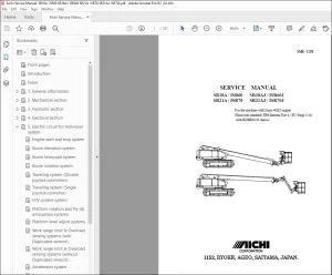
This manual describes correct adjustment and servicing procedures
for SR210 Self-propelled aerial platform in order to ensure the most
effective use of superb performance and excellent features for your
satisfaction.
Read this manual carefully and understand the descriptions correctly
before making any repair or maintenance works.
Always be sure of the following items when conducting repair or
maintenance works. * Use only the spare parts approved by the manufacturer, particularly
for load-supporting and safety-related components. * Do not make any modifications to the machine without obtaining the
manufactures approval. * The design check, the manufacturing check as well as the practical .
test should be conducted by the approved agent, if the modification
which would affect the stability, strength or performance of the machine·
is made.
Please, note that the numerical values in this manual may be subject to
change due to engineering improvement.
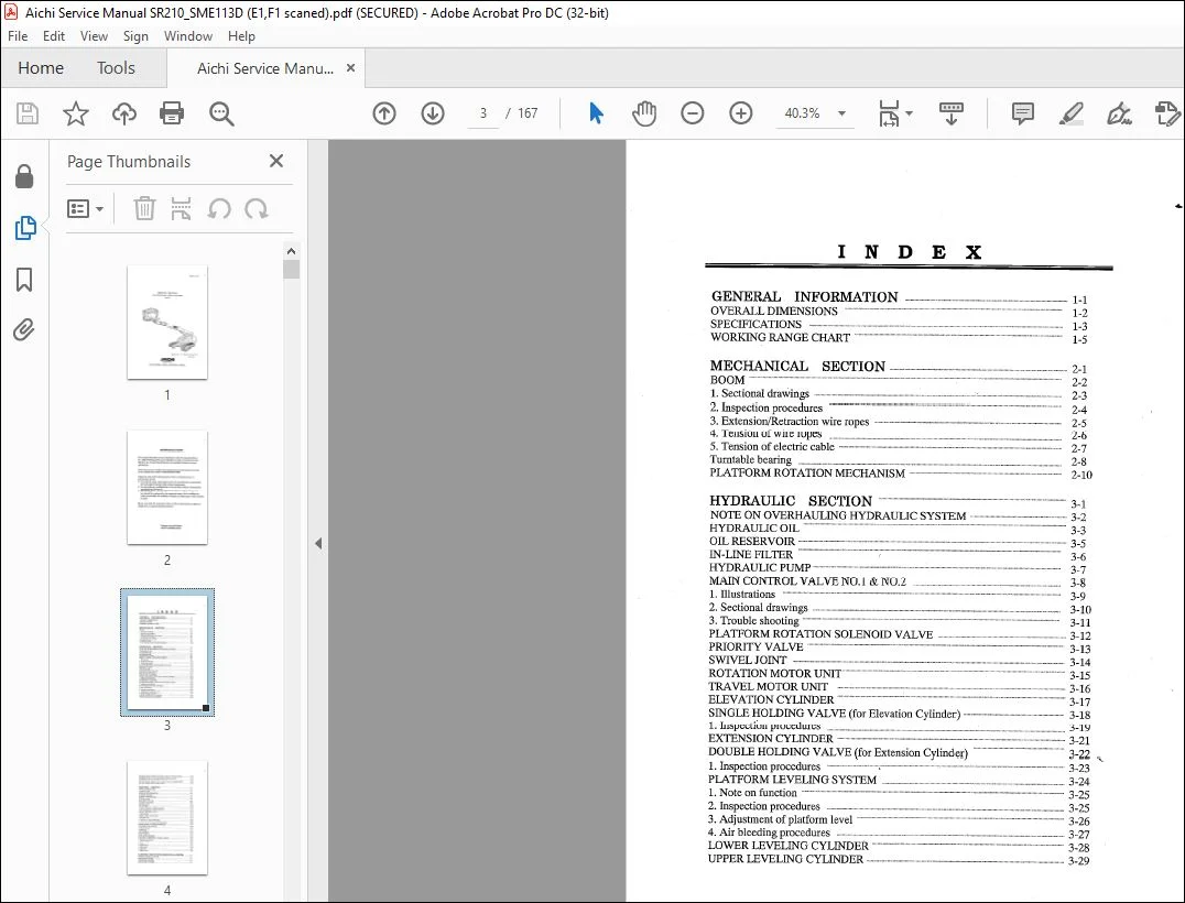
TABLE OF CONTENTS:
Aichi SR-210 SERVICE MANUAL SME-113 D – PDF DOWNLOAD
GENERAL INFORMATION 1 1
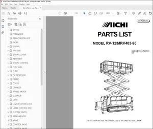
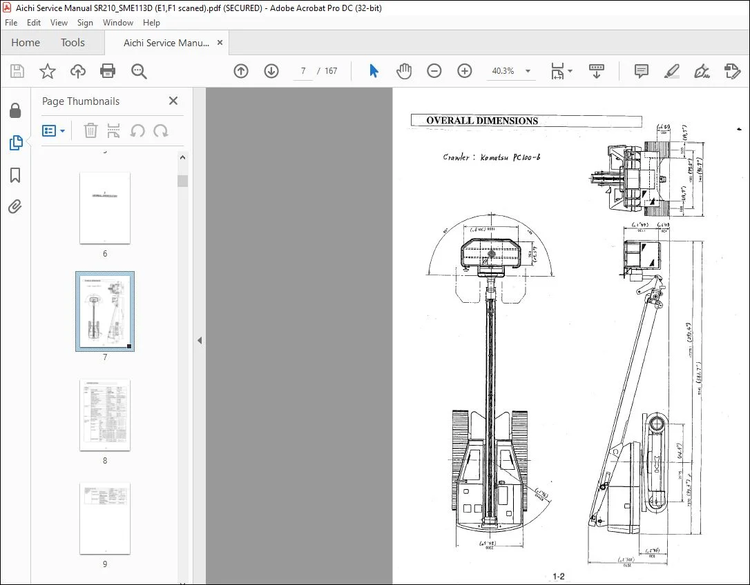
OVER&LDIMENSIONS 1 2
SPECIFICATIONS 1 3
WORKIN”G RANGE CHART 1 5
MECHANICAL SECTION 2 1
BOOM 2 2
1 Sectional drawings 2 3
2 Inspection procedures 2 4
3 Extension/Retraction wire ropes 2 5
4 Tension of wire ropes 2 6
5 Tension of electric cable 2 7
Turntable bearing 2 8
PIATFORM ROTATION MECHANISM 2 10
HYDRAULIC SECTION 3 1
NOTE ON OVERHAULING HYDRAULIC SYSTEM 3 2
HYDRAULIC OIL 3 3
OIL RESERVOIR 3 5
IN LINE FILTER : 3 6
HYDRAULIC PUMP : 3 7
MAIN CONTROL VALVE NO l & NO 2 3 8
1 Illustrations 3 9
2 Sectional drawings 3 10
3 Trouble shooting 3 11
PIATFORMROTATIONSOLENOIDVALVE 3 12
PRIORITY VAL VE 3 13
SWIVEL JOINT 3 14
ROTATION MOTOR UNIT : 3 15
TRAVEL MOTOR UNIT : 3 16
ELEVATION CYLINDER 3 17
SINGLE HOLDING VALVE (for Elevation Cylinder) 3 18
1 Inspection procedures 3 19
EXTENSION CYLINDER 3 21
DOUBLE HOLDING VAL VE (for Extension Cylinder) 3 22 ,
1 Inspection procedures ~ 3 23
PLATFORM LEVELING SYSTEM 3 24
1 Note on function 3 25
2 Inspection procedures : : 3 25
3 Adjustment of platform level 3 26
4 Air bleeding procedures 3 27
LOWER LEVELING CYLIN”DER 3 28
UPPER LEVELING CYLINDER 3 29
DOUBLE PILOT CHECK VAL VE (for Upper Leveling Cylinder) 3 30
COMBINATION VALVE (for Platform Leveling system) 3 31
PLATFORM LEVEL SOLENOID VAL VE 3 32
DOUBLE PILOT CHECK VAL VE (for Platform Leveling System) 3 33
TRAVELSPEEDSELECTOR VALVE : 3 34
ELECTRIC SECTION 4 1
UPPER CO:N’fROL BOX 4 2
1 Electric circuit 4 3
LEVER POTENTIOMETER 4 4
CONTROL BOARD 4 5
LOWER CONTROL BOX 4 6
1 Electric circuit 4 7
MAIN KEY SWITCH 4 8
INTERFACE BOARD 4 9
1 Electric circuit ; 4 11
CPU BOARD 4 12
1 Note on function of CPU board (1/2) ~ 4 13
2 Note on function of CPU board (2/2) 4: 14
VALVECONTROLUNIT 4 15
1 Specification 4 15
2 Input / Output characteristic 4 15
3 External view 4 15
4 Function of valve control unit 4 16
5 Function of trimmers and LEDs 4 17
FUNCTION OF LOWER CONTROL BOX 4 18
BOOM ANGLE & LENGTH SENSORS 4 19
ACCELERATOR MOTOR 4 20
1 Electric circuit : 4 21
2 Inspection 4 21
TILT SENSOR 4 22
FOOT SWITCH 4 23
FUEL LEVEL SENSOR : 4 24
ELECTRIC COMPONENT attached to Engine 4 25
1 Engine stop solenoid : 4 25
2 Glow indicator 4 25
3 Timer 4 26
4 Starter motor 4 27
5 Safety relay 4 28
‘ , 6 Alternator 4 29
7 Battery relay 4 30
ELECTRIC CIRCUIT FOR INDIVIDUAL SYSTEM s 1
ENGINE CONTROL SYSTEM 5 2
ROTATION SYSTEM 5 3
EXTENSION SYSTEM : 5 4
ELEVATION SYSTEM 5 5
TRAVEL (RIGHT) SYSTEM : 5 6
TRAVEL (LEFT) SYSTEM 5 7
ACCEIBRA TOR SYSTEM : 5 8
PLATFORM ROTATION & PLATFORM LEVEL SYSTEM 5 9
TILT WARNING, HORN & WORKING LIGHT SYSTEM 5 10
MOTION ALARM SYSTEM 5 11
EMERGENCY PUMP SYSTEM 5 12
ADJUSTMENT SECTION 6 1
RELIEF VALVE Pl andP4 6 2
RELIEF VALVE P2 6 3
RELIEF VALVE P3 := : : , 6 4
OPERATIONAL SPEED 6 5
1 Measurement procedures of Maximum Operational Speed 6 6
2 Adjustment procedures of Operational Speed 6 7
ADJUSTMENT of CPU BOARD : 6 12
1 Calibration of Boom Angle and Length Sensors 6 13
2 Adjustment of Limited Rotation Speed 6 13
3 Adjustment of Limited Elevation Speed 6 14
4 Adjustment of Limited Travel Speed 6 15
5 Adjustment of Stroke End Shockless Range 6 16
6 Adjustment of Pivot Turn Speed u 6 17
7 Adjustment of Spin tum Speed 6 18
ADJUSTMENT DATA SHEET n 6 19
APPENDIX 7 1
TROUBLE SHOOTING 7 2
IDENTIFICATIONS OF CONTROL DEVICES & FUSES 7 4
HYDRA ULIC
Questions? Email us: [email protected]
https://vimeo.com/739338733
PLEASE NOTE:
- This is the SAME MANUAL used by the dealerships to diagnose your vehicle
- No waiting for couriers / posts as this is a PDF manual and you can download it within 2 minutes time once you make the payment.
- Your payment is all safe and the delivery of the manual is INSTANT – You will be taken to the DOWNLOAD PAGE.
- So have no hesitations whatsoever and write to us about any queries you may have : heydownloadss @gmail.com
I.G