Aichi SR181 SERVICE MANUAL SME-111-B – PDF DOWNLOAD
Original price was: $80.95.$22.95Current price is: $22.95.
Aichi SR181 SERVICE MANUAL SME-111-B – PDF DOWNLOAD
Description
Aichi SR181 SERVICE MANUAL SME-111-B – PDF DOWNLOAD
IMAGES PREVIEW OF THE MANUAL:
DESCRIPTION:
Aichi SR181 SERVICE MANUAL SME-111-B – PDF DOWNLOAD
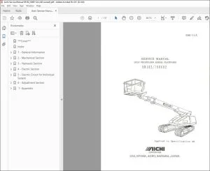
This manual describes correct adjustment and servicing
procedures for CRAWLER TYPE AERIAL PLATFORM SR 181’in order
to ensure the most effective use of the superb performance and
excellent operation features for your satisfaction.
Read this manual carefully and understand the descriptions
correctly.
We sincerely hope that this manual assists you in your servicing
work.
Please note that the numerical values in this manual may be
subject to change due to engineering modification and improvement.
TABLE OF CONTENTS:
Aichi SR181 SERVICE MANUAL SME-111-B – PDF DOWNLOAD
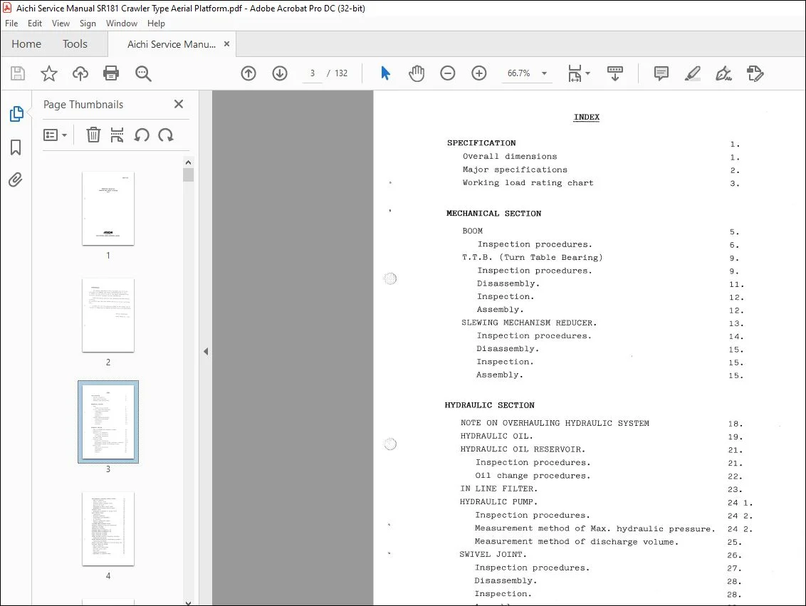
INDEX
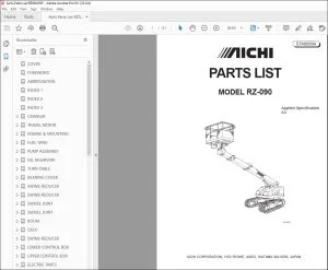
SPECIFICATION
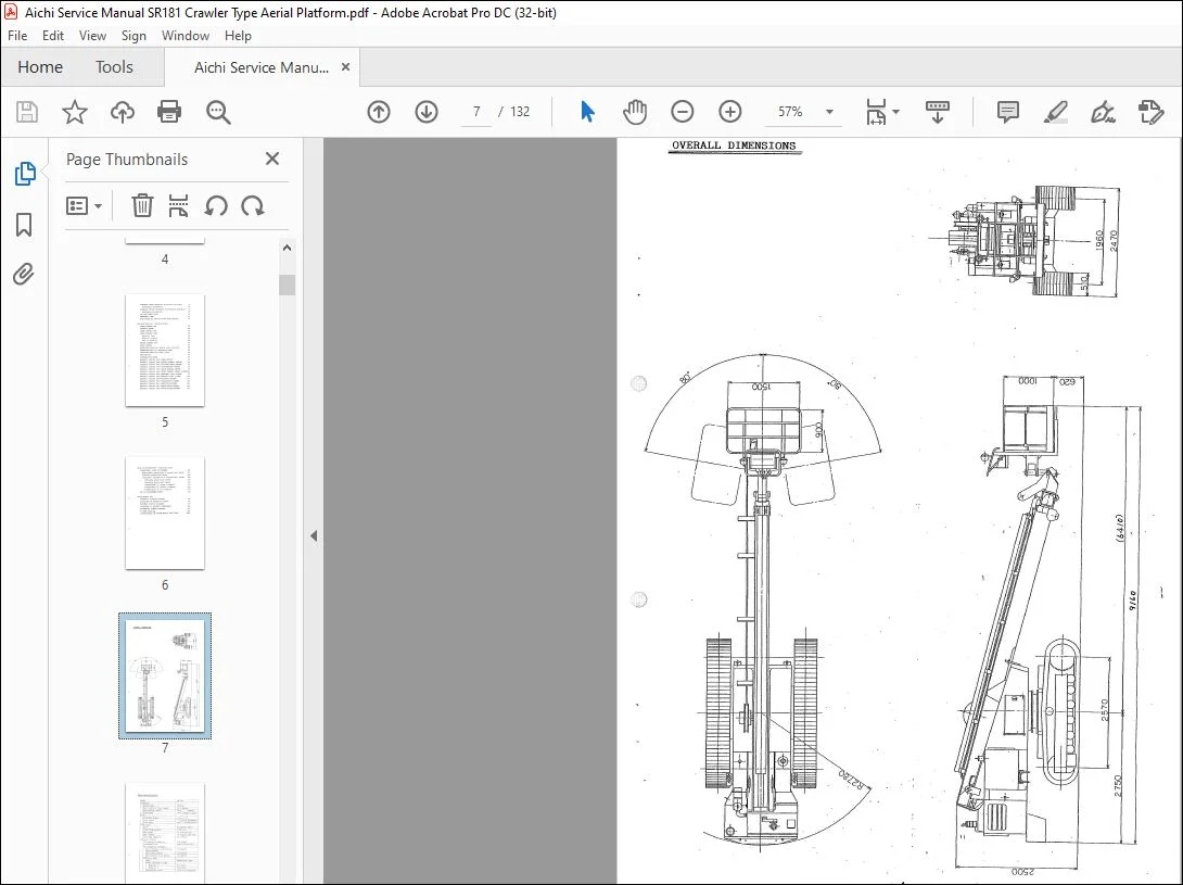
Overall dimensions
Major specifications
Working load rating chart
MECHANICAL SECTION
BOOM
Inspection procedures.
T.T.B. (Turn Table Bearing)
Inspection procedures.
Disassembly.
Inspection.
Assembly.
SLEWING MECHANISM REDUCER.
Inspection procedures.
Disassembly.
Inspection.
Assembly.
HYDRAULIC SECTION
NOTE ON OVERHAULING HYDRAULIC SYSTEM
HYDRAULIC OIL.
HYDRAULIC OIL RESERVOIR.
Inspection procedures.
Oil change procedures.
IN LINE FILTER.
HYDRAULIC PUMP.
Inspection procedures.
Measurement method of Max. hydraulic pressure.
Measurement method of discharge volume.
SWIVEL JOINT.
Inspection procedures.
Disassembly.
Inspection.
Assembly.
MAX.HYDRAULIC PRESSURE CONTROL SYSTEM 29
Note on function 29
Remote control valve 30
Pressure select solenoid valve 31
Main relief valve 31
Adjustment of Main relief valve 32
Adjustment of Remote control valve 33
PRIORITY VALVE 34
Adjustment procedures of Relief valve 34
MAIN CONTORL VALVE 36
Ilustration 37
Sectional drawings 38
Disassembly and Reassembly 39
Air bleeding 47
Specific tightening torque 48
Trouble shooting 49
PLATFORM SWING SOLENOID VALVE 50
HYDRAULIC MOTOR{for Rotation mechanism) 51
ELEVATION CYLINDER 53
TELESCOPING CYLINDER 54
PLATFORM SWING CYLINDER{for 45) 55
Q PLATFORM SWING CYLINDER{for 80) 56
UPPER LEVELLING CYLINDER 57
LOWER LEVELLING CYLINDER 58
SINGLE HOLDENG VALVE{for Elevation cylinder) 59
Inspection procedures 60
DOUBLE HOLDING VALVE(for Telescoping cylinder) 62
Inspection procedures 63
DOUBLE PILOT CHECK VALVE(for Platform swing CYL) 64
PLATFORM LEVELLING SYSTEM 65
Note on function 66
Double pilot check valve 66
Overload relief valve 67
Stop valve 68
Inspection procedures 69
Adjustment of platform level 70
THROTTLE CHECK VALVE(for Elevation cylinder) 71
Adjustment procedures 71
OVERLOAD RELIEF VALVE(for Telescoping cylinder) 72
Adjustment procedures 72
IN-LINE CHECK VALVE 74
EMERGENCY PUMP 75
STOP VALVE{for Manual bleed down system) 76
ELECTRIC SECTION
UPPER CONTROL BOX 78
POTENTIOMETER 80
LOWER CONTROL BOX 81
VALVE CONTROL UNIT 83
External view 84
Electric circuit 85
Note on function 86
ENGINE CONTROL BOX 87
SLOPE SENSOR 88
CONTACTOR{CR36) (for Engine stop solenoid) 89
CONTACTOR(CRC) {for Emergency pump) 89
CONTACTOR{CR60) {for Head light) 89
FOOT SWITCH 90
ACCELERATION MOTOR 91
ELECTRIC CIRCUIT FOR 11 POWER SUPPLY11 93
ELECTRIC CIRCUIT FOR 11 ENGINE CONTROL SYSTEM11 94
ELECTRIC CIRCUIT FOR “PLATFORM SWING SYSTEM” 95
ELECTRIC CIRCUIT FOR “ACCELERATION SYSTEM” 96
ELECTRIC CIRCUIT FOR “SLOPE WARNING SYSTEM11 97
ELECTRIC CIRCUIT FOR 11 UPPER CONTROL CANCEL SYSTEM11 98
ELECTRIC CIRCUIT FOR “EMERGENCY PUMP SYSTEM” 99
ELECTRIC CIRCUIT FOR “WORKING LIGHT & HORN” 100
ELECTRIC CIRCUIT FOR “ROTATION SYSTEM11 101
ELECTRIC CIRCUIT FOR “TELESCOPING SYSTEM11 102
ELECTRIC CIRCUIT FOR 11 ELEVATION SYSTEM” 103
ELECTRIC CIRCUIT FOR 11 TRAVEL {LEFT) SYSTEM” 104
ELECTRIC CIRCUIT FOR 11 TRAVEL(RIGHT)SYSTEM11 105
~DJUSTMENT SECTION
OPERATIONAL SPEED ADJUSTMENT
Measurement procedures of operational
Standard operational speed
Adjustment procedures of “Operational
!.Minimum operational speed
2.Maximum operational speed
3.Adjust.ment of “Delay trimmers”
4.Adjust.ment of “Dither trimmers”
5 .Adjustment. of “Tr trimmers”
SR-181 ADJUSTMENT SHEET
~PPENDIX
HYDRAULIC CIRCUIT DIAGRAM
LOCATIONS OF HYDRAULIC VALVES
ELECTRIC CIRCUIT DIAGRAM
LOCATIONS OF ELECTRIC COMPONENTS
TIGHTENING TORQUE STANDARD
Customer Support: [email protected]
https://vimeo.com/739332656
PLEASE NOTE:
- This is the SAME MANUAL used by the dealerships to diagnose your vehicle
- No waiting for couriers / posts as this is a PDF manual and you can download it within 2 minutes time once you make the payment.
- Your payment is all safe and the delivery of the manual is INSTANT – You will be taken to the DOWNLOAD PAGE.
- So have no hesitations whatsoever and write to us about any queries you may have : heydownloadss @gmail.com
I.G