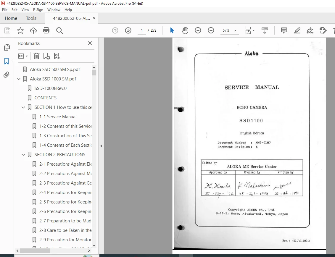
ALOKA SSD-1100 Diagnostic Ultrasound Service Manual – PDF DOWNLOAD
Original price was: $65.00.$21.95Current price is: $21.95.
The official Aloka SSD-1100 Ultrasound Service Manual provides detailed procedures for maintenance, troubleshooting, calibration, and circuit board replacement of the SSD-1100 diagnostic ultrasound system. It includes system block diagrams, adjustment procedures, performance check forms, disassembly instructions, and schematic diagrams. Ideal for biomedical engineers and field technicians servicing Aloka ultrasound units.
Description
ALOKA SSD-1100 Diagnostic Ultrasound Service Manual – PDF DOWNLOAD
Description
⚙️ Overview
The Aloka SSD-1100 Service Manual (Document No. MN2-0218) is a comprehensive guide for authorized service engineers responsible for the maintenance and repair of the SSD-1100 ultrasound diagnostic system.
It outlines electrical, mechanical, and safety precautions, as well as systematic diagnostic methods and board-level repair workflows.
This manual is essential for ensuring safety, reliability, and optimal image performance of the system.
📑 Table of Contents & Key Sections
SECTION 1 – How to Use This Manual
Purpose and usage overview
Repair principle: replace faulty PCB with new one
Structure of manual (Service Instructions, Operation Principle, Parts List, Appendix)
SECTION 2 – Precautions
Electrical, mechanical, and biological safety measures
Handling static-sensitive (SMD) PCBs
Grounding and proper disassembly procedures
CRT monitor servicing cautions
Germ-handling procedures for transducer servicing
SECTION 3 – Before Repairing
Service workflow chart (Reception → Diagnosis → Repair → Operation Check → Report)
Repair documentation standards and customer reporting
Field preparation and inspection process
Upgrade and improvement work procedure
Service message and warning display information
SECTION 4 – Principle of System Operation
System specifications and configuration
Scanning: Electronic Linear / Convex / Mechanical Sector (with SCU-1000)
Display modes: B, 2B, B/M, M
ECG/PCG display and synchronization
Power supply: 100–240 V AC, 50/60 Hz
System Control Architecture
CPU control and bus communication
TX/RX circuit and focusing principles
Digital Imaging Unit (DIU) and Auto B-Gain Control (ABC) system
Cine Memory, Mechanical Scanner, and Physiological Signal Units
Power Supply and optional Data Management Subsystem
SECTION 5 – Schematics
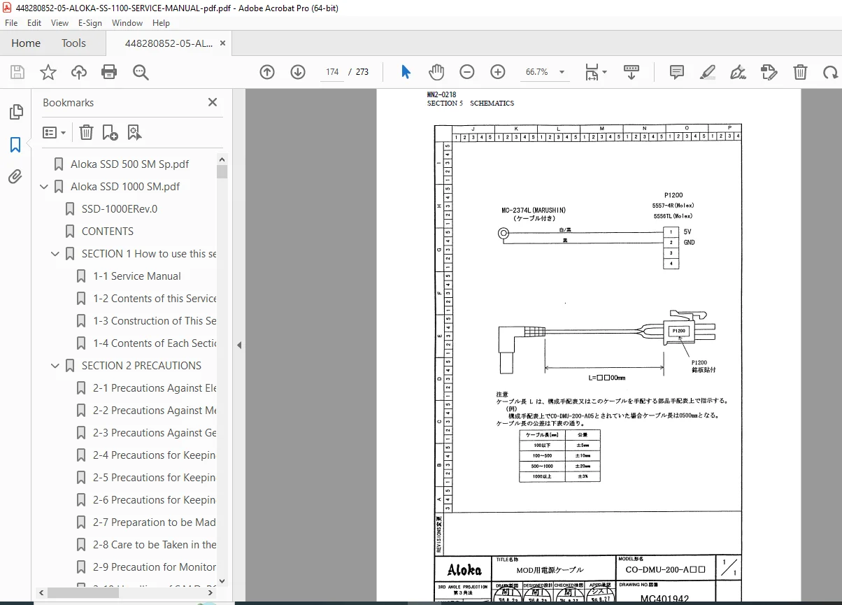
Complete cable connection diagrams, circuit diagrams of field-replaceable PCBs,
and TV monitor/power supply schematics
SECTION 6 – Troubleshooting
Step-by-step fault isolation and diagnostic procedure
Recommended tools and measurement equipment
Hints for symptom identification and first-level corrective measures
SECTION 7 – Adjustment Procedure
PCB and sub-unit calibration after replacement
Gain, focus, and synchronization alignment procedures
SECTION 8 – Performance Check
Post-repair operation verification
Performance check forms and record sheets
SECTION 9 – Disassembling Procedure
Illustrated disassembly and reassembly steps for major components
SECTION 10 – Parts List
Mechanical and electrical components eligible for field replacement
SECTION 11 – Service Information
Technical bulletins, revision history, and upgrade notices
Appendix – Manual Change Information
Revision control, updates, and modification notes
⚙️ Key Technical Features
Covers electronic, convex, and mechanical scanning probe systems
Includes block diagrams and signal flow for major PCBs (TX/PRE AMP, RX FOCUS, MAIN AMP, GEU I.T.F., DIU, etc.)
Describes Auto B-Gain Control (ABC) and Cine Memory architecture
Provides signal list tables, connector pinouts, and voltage measurement references
Comprehensive system schematics for SSD-1100 and compatible modules
📄 Short File Details
| Detail | Description |
|---|---|
| Manual Name | Aloka SSD-1100 Diagnostic Ultrasound Service Manual |
| Model Covered | SSD-1100 (and compatible units like SSD-1000, SCU-1000, PEU-1000) |
| Document No. | MN2-0218 |
| Edition / Year | Latest Revision |
| Manual Type | Full Service, Maintenance, and Schematics Manual |
| PDF Quality | High (Clear text, schematics, and PCB diagrams) |
| Total Pages | 273 |
| Language | English |
| Manufacturer | Aloka Co., Ltd. (Japan) |