Trusted Business
Verified & Licensed
Virus Free Files
100% Safe Downloads
Secure Payment
SSL Protected
Instant Delivery
Available Immediately
Ammann ARS 70 Single Drum Roller Workshop Manual 3035068 PDF
$28.95
Instant PDF Download
Available immediately
Save to Your Device
Download & keep forever
Antivirus Scanned
100% virus-free
Trusted Worldwide
175,000+ customers
Description
Ammann ARS 70 Single Drum Roller Kubota V3307-CR-TE5 EU Stage V / U.S. EPA Tier 4f Workshop Manual SN 3035068 – PDF DOWNLOAD
FILE DETAILS:
Ammann ARS 70 Single Drum Roller Kubota V3307-CR-TE5 EU Stage V / U.S. EPA Tier 4f Workshop Manual SN 3035068 – PDF DOWNLOAD
Language : English
Pages : 270
Downloadable : Yes
File Type : PDF
IMAGES PREVIEW OF THE MANUAL:
TABLE OF CONTENTS:
Ammann ARS 70 Single Drum Roller Kubota V3307-CR-TE5 EU Stage V / U.S. EPA Tier 4f Workshop Manual SN 3035068 – PDF DOWNLOAD
Contents 4
1 Introduction 9
1 1About this workshop manual 13
1 1 1Who is the workshop manual intended for 13
1 1 2Purpose 13
1 1 3Applicability of the workshop manual 13
1 1 4Validity of the workshop manual 13
2 Safety measures and instructions 15
2 1Safety rules 16
2 2Environmental and hygiene principles 19
2 3Fire prevention 20
2 4Claim conditions and disclaimer of liability 20
3 Specification manual 21
3 1Basic data 22
3 2Dimensioned drawing of the machine 24
3 3Technical data 26
4 Specification of operating fluids 29
4 1Engine oil 30
4 2Fuel 31
4 3Coolant 31
4 4Hydraulic oil 32
4 5Gearbox oil 32
4 6Lubricating grease 33
4 7Windshield washer liquid 33
4 8Air-conditioning filling 33
4 9Fills 34
5 Frame 35
5 1Description of basic elements 37
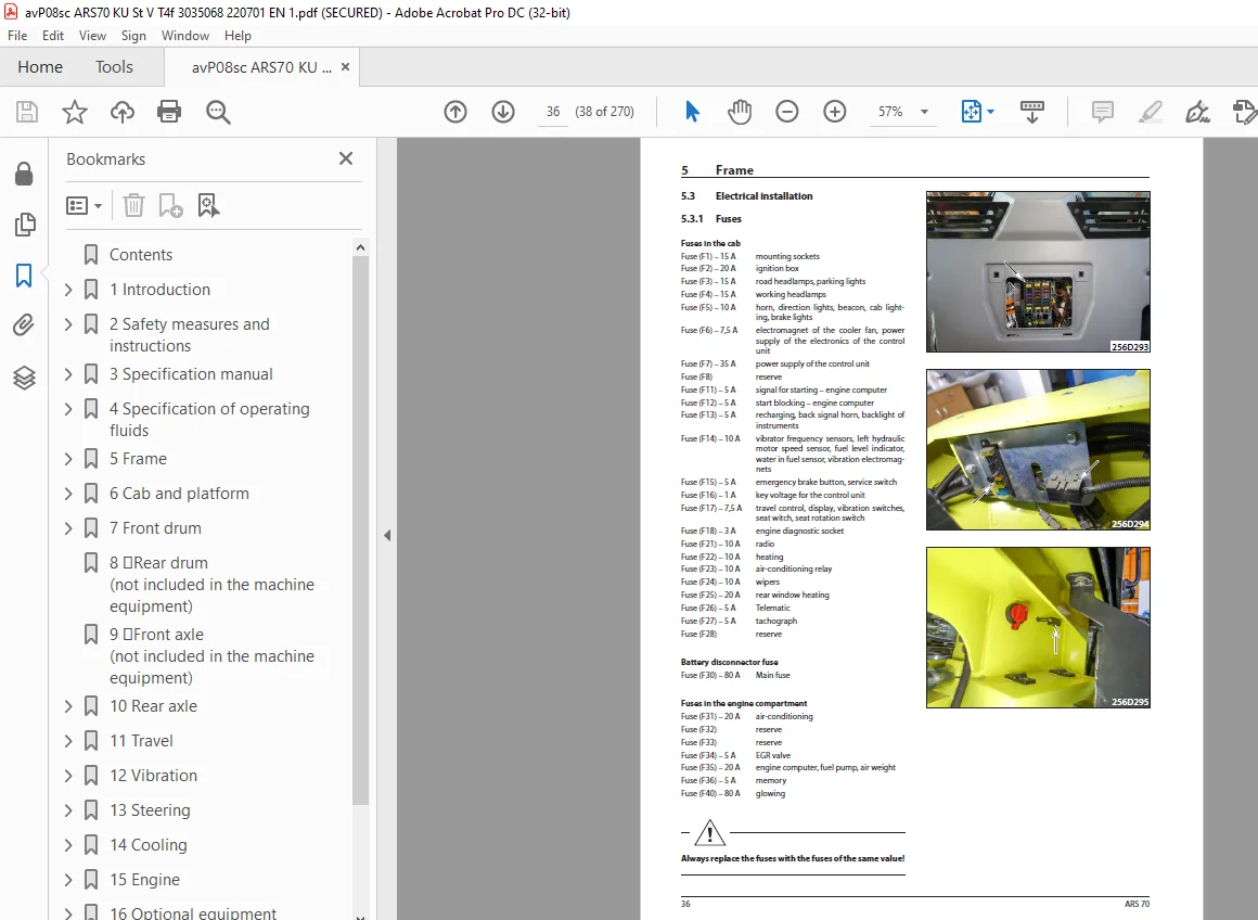
5 3Electrical installation 38
5 3 1Fuses 38
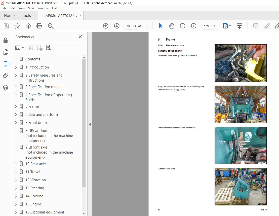
5 4Mechanical parts 40
15 4Mechanical parts 42
5 5Fuel tank 45
5 5 1Fuel level check 45
5 5 2Fuel replenishment 45
5 5 3Fuel drainage 46
5 5 4Fuel tank cleaning 47
5 6Hydraulic tank 48
5 6 1Hydraulic oil level check 48
5 6 2Hydraulic oil replenishment 49
5 6 3Hydraulic oil drainage 50
5 6 4Hydraulic oil filter replacement 51
6 Cab and platform 53
6 1Description of basic elements 55
6 3Electrical installation 55
6 3 2Output layout on the steering column 56
6 3 6Control lever panel 57
6 3 7Other components 57
6 3 7 1Control unit of the machine A2 57
6 4Mechanical parts 58
6 4 1Setting of the control force of the travel control 63
6 5Cab 64
6 5 1Cab removal 64
6 5 2Cab installation 69
6 7 Driver’s stand 79
6 7 4Display replacement 79
7 Front drum 81
7 1Description of basic elements 83
7 2Hydraulic parts 84
7 4Mechanical parts 85
7 4 1Replacement of vibration unit bearings 85
7 4 1 1Drum disassembly from the frame 85
7 4 1 2Disassembly of bearings of the vibration unit 91
7 4 1 3Assembly of bearings of the vibration unit 95
7 4 1 4Drum removal 100
8 Rear drum (not included in the machine equipment) 105
9 Front axle (not included in the machine equipment) 107
10 Rear axle 109
10 1Description of the basic elements 110
10 2Hydraulic parts 110
10 2 1Travel hydraulic motor 110
10 2 2Travel hydraulic motor replacement 111
10 4Mechanical parts 111
10 4 1Gearbox 111
10 4 2Wheels 112
10 4 3Wheel disassembly 112
11 Travel 113
11 1Description of basic elements 114
11 2Hydraulic parts 115
11 2 1Travel pump replacement 118
11 2 2Flushing block replacement 121
11 2 3Travel hydraulic motor replacement 122
11 2 3 1Drum travel hydraulic motor replacement 122
11 2 3 2Rear axle travel hydraulic motor replacement 125
11 2 4Brake block replacement 129
11 3Electrical installation 132
11 3 1Travel pump coils replacement 132
11 3 2Travel hydraulic motor coils replacement 132
11 4Mechanical parts 132
11 4 1BOVEX coupling replacement 132
12 Vibration 133
12 1Description of basic elements 134
13 Steering 135
13 1Description of basic elements 136
13 2Hydraulic parts 138
13 2 1Linear hydraulic motor replacement 138
13 2 2Steering linear hydraulic motor seal replacement 141
13 2 3Steering hydraulic unit replacement 145
13 2 3 1Disassembly of the hydraulic unit of the steering unit 145
13 2 3 2Assembly of the hydraulic unit of the steering unit 148
13 2 4Steering pump 151
13 3Electrical installation 151
13 3 1Display replacement 151
13 3 2Travel control replacement 152
13 4Mechanical parts 154
13 4 2Steering wheel removal 154
14 Cooling 155
14 1Description of basic elements 156
14 2Hydraulic parts 156
14 2 1Cooling hydraulic motor replacement 157
14 3Electrical installation 161
14 3 1Replacement of the electromagnet coil of the cooling hydraulic motor 161
14 4Mechanical parts 162
14 4 1Replacement of the cooling fan, cooling fan spacer 162
15 Engine 165
15 1Description of basic elements 166
15 2Hydraulic parts 171
15 2 1Steering pump replacement 171
15 3Electrical installation 172
15 3 1Batteries 172
15 3 2Alternator replacement 172
15 3 3Starter replacement 172
15 4Mechanical parts 173
16 Optional equipment 203
16 1Optional equipment list 204
17 General procedures 205
17 2Electrical installation 206
17 2 1Travel pump magnetic coil check 206
17 2 2Preparation for welding works 207
17 2 3Starting the battery by means of another battery (jumping) 207
17 2 4Charging the battery with a charger 208
17 2 5Long-term storage 208
17 2 6Battery replacement 208
17 4Calibration and setting 209
17 4 1Pump current calibration 209
17 4 1 1Required material 209
18 Troubleshooting 211
18 1SW error diagnostics 212
18 1 1Error codes 212
18 1 1 1Machine errors 212
18 1 1 2Errors due to safety functions 214
18 1 1 3Errors at the inputs 215
18 1 1 4Errors at the outputs 216
18 1 1 5ACE errors 218
18 1 1 6System errors 219
18 1 1 7Engine errors 220
18 1 3Travel control check 224
18 2 14Travel control 224
18 2 14 1Travel control replacement 224
18 2 14 2Travel lever switch check and replacement 224
19 Appendices 225
19 1Hydraulic system 227
19 1 1Travel pump zero position adjustment 227
19 1 1 1Travel pump magnetic coil check 227
19 2Wiring diagram 228
19 3Hydraulic diagram – wheel lock 236
19 4Hydraulic diagram – ATC inter-axle lock 238
19 5Harnesses 240
19 6Check of the screw connections for tightening 263
19 7List of spare parts specified in the publication 265
Questions? Email us: [email protected]
https://vimeo.com/899523200?share=copy
S.V