Trusted Business
Verified & Licensed
Virus Free Files
100% Safe Downloads
Secure Payment
SSL Protected
Instant Delivery
Available Immediately
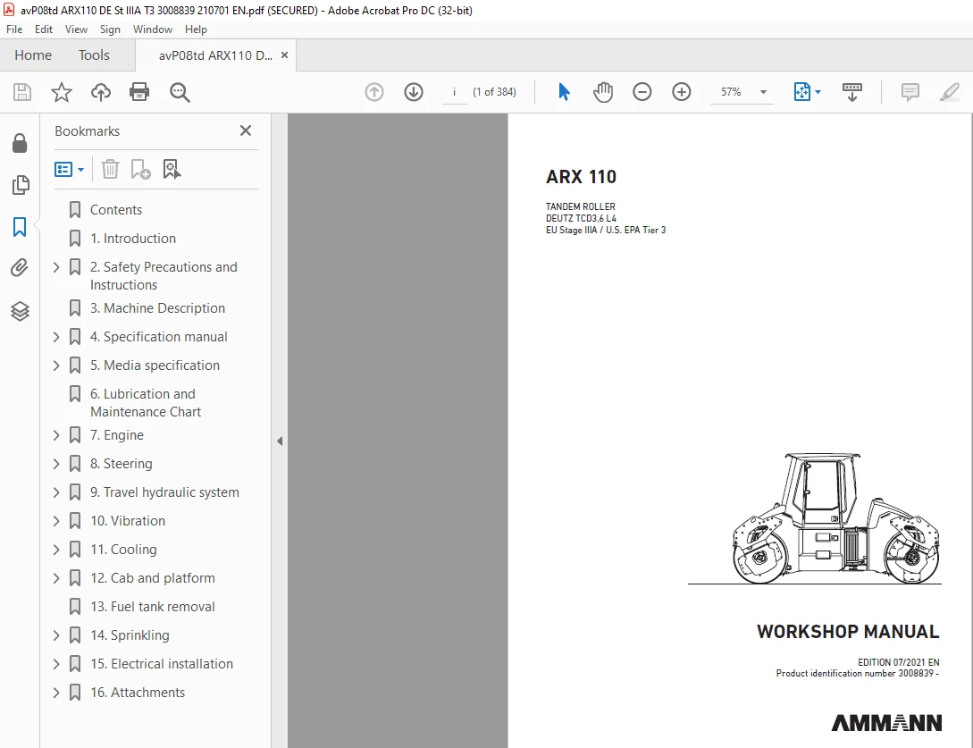
Ammann ARX 110 Tandem Roller Workshop Manual 3008839 PDF
$28.95
Instant PDF Download
Available immediately
Save to Your Device
Download & keep forever
Antivirus Scanned
100% virus-free
Trusted Worldwide
175,000+ customers
Description
Ammann ARX 110 Tandem Roller Deutz TCD3,6 L4 EU Stage IIIA / U.S. EPA Tier 3 Workshop Manual SN 3008839 – PDF DOWNLOAD
FILE DETAILS:
Ammann ARX 110 Tandem Roller Deutz TCD3,6 L4 EU Stage IIIA / U.S. EPA Tier 3 Workshop Manual SN 3008839 – PDF DOWNLOAD
Language : English
Pages : 384
Downloadable : Yes
File Type : PDF
IMAGES PREVIEW OF THE MANUAL:
TABLE OF CONTENTS:
Ammann ARX 110 Tandem Roller Deutz TCD3,6 L4 EU Stage IIIA / U.S. EPA Tier 3 Workshop Manual SN 3008839 – PDF DOWNLOAD
Contents 4
1 Introduction 7
2 Safety Precautions and Instructions 11
2 1 Safety Regulations 12
2 2 Environmental measures and health precautions 15
2 3 Fire precautions 16
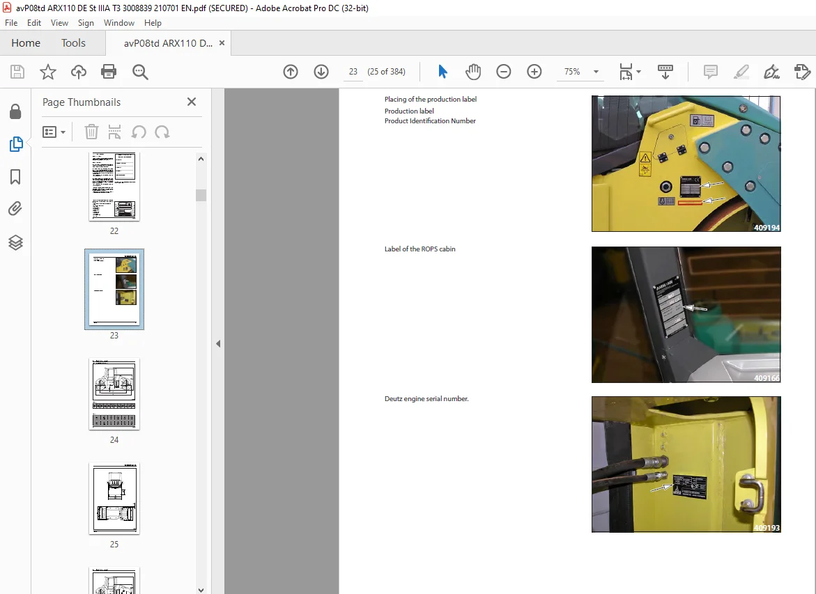
3 Machine Description 19
4 Specification manual 23
4 1 Basic specification 24
4 2 Machine dimension scheme 26
4 3 Technical data 30
5 Media specification 35
5 1 Engine oil 36
5 2 Fuel 37
5 3 Cooling liquid 37
5 4 Hydraulic oil 38
5 5 Gearbox oil 38
5 6 Lube grease 39
5 7 Glass washer fluid 39
5 8 Drum cooling liquid 39
5 9 Air Conditioning filling 39
5 10 Vibratory oil 39
5 11 Emulsion 39
5 12 Media 40
6 Lubrication and Maintenance Chart 41
7 Engine 47
7 1 Description of the engine and basic components 49
7 2 Technical data of the manufacturer 51
7 3 Troubleshooting 52
7 4 Engine removal 55
8 Steering 75
8 1 Description of basic components 77
8 2 Technical data of the manufacturer 78
8 3 Steering pump removal 79
8 4 Removal of the linear hydraulic motor of the steering and crab 84
8 4 1 Linear hydraulic motor – crab (90/45-125) 86
8 4 2 Linear hydraulic motor – steering (90/45-420) 88
8 4 3 Replacement of sealings of the linear hydraulic motor 90
8 5 Steering unit removal 94
8 6 Removal of the hydraulic tank 98
8 7 Steering wheel removal 103
8 8 Steering pillar removal 106
8 9 Removal of the steering joint from the machine 109
8 9 1 Removal of bearings of the steering joint 118
8 9 2 Removal of bearings of the arm 126
9 Travel hydraulic system 133
9 1 Description of basic components 135
9 2 Technical data of the manufacturer 135
9 3 Travel hydraulic motor removal 136
9 4 Travel gearbox removal 140
9 5 Travel pump removal 146
10 Vibration 153
10 1 Description of basic elements of vibration hydraulics 155
10 2 Technical data of the manufacturer 156
10 3 Removal of vibration hydraulic motor 157
10 4 Removal of vibration pump on front drum 164
10 5 Removal of vibration hydraulic pump from rear drum 168
10 6 Removal of drum from machine 172
10 7 Removal of vibrator bearings 182
10 8 Removal of flange bearings and damper plate 195
10 9 Removal of rubber-metals from drum 204
11 Cooling 211
11 1 Description of basic components of the cooling hydraulics 212
11 2 Technical data of the manufacturer 213
11 3 Removal of the cooling hydraulic motor and propeller 214
11 4 Cooling pump removal 220
11 5 Combined cooler disassembly 225
12 Cab and platform 235
12 1 Ball valve heating removal 237
12 2 Heating removal 240
12 3 Heating fan removal 244
12 4 Cab removal 248
12 5 Platform removal 254
12 6 Removal of rubber-metals of the platform 267
13 Fuel tank removal 277
14 Sprinkling 285
14 1 Sprinkling pump removal 286
14 2 Water tank removal 290
15 Electrical installation 297
15 1 Measurement technique 299
15 2 Safety and instruction 300
15 3 Fuse positioning 301
15 4 Display removal 302
15 5 Seat switch removal 305
15 6 Removal of the travel lever and switches 309
15 7 Adjust pulse sensor 314
15 8 Accumulators 317
15 9 Alternator 320
15 10 Starter 323
16 Attachments 327
16 1 Wiring diagram 328
16 2 Wiring diagram of chip spreader 334
16 3 Electric installations cable harnesses 337
16 4 Hydraulic system diagram ARX 110 366
16 5 Hydraulic system diagram ARX 110 HF 368
16 6 Hydraulic system diagram ARX 110 C 370
16 7 Hydraulic diagram of chip spreader 372
16 8 Check the tightening of bolted connections 374
16 9 List of spare parts specified in the publication 376
16 10 List of groups from spare parts catalog used in the publication 376
16 11 Error codes 377
Contact us: [email protected]
S.V