Trusted Business
Verified & Licensed
Virus Free Files
100% Safe Downloads
Secure Payment
SSL Protected
Instant Delivery
Available Immediately
Ammann ARX 110 Tandem Roller Workshop Manual 3031385 PDF
$28.95
Instant PDF Download
Available immediately
Save to Your Device
Download & keep forever
Antivirus Scanned
100% virus-free
Trusted Worldwide
175,000+ customers
Description
Ammann ARX 110 Tandem Roller Deutz TCD3,6 L4 EU Stage IIIA / U.S. EPA Tier 3 Workshop Manual SN 3031385 – PDF DOWNLOAD
FILE DETAILS:
Ammann ARX 110 Tandem Roller Deutz TCD3,6 L4 EU Stage IIIA / U.S. EPA Tier 3 Workshop Manual SN 3031385 – PDF DOWNLOAD
Language : English
Pages : 384
Downloadable : Yes
File Type : PDF
IMAGES PREVIEW OF THE MANUAL:
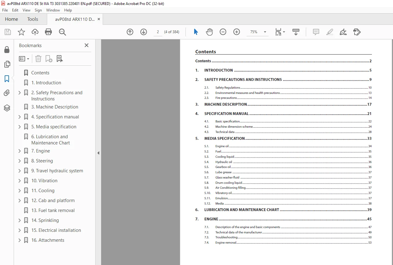
TABLE OF CONTENTS:
Ammann ARX 110 Tandem Roller Deutz TCD3,6 L4 EU Stage IIIA / U.S. EPA Tier 3 Workshop Manual SN 3031385 – PDF DOWNLOAD
Contents 4
1 Introduction 7
2 Safety Precautions and Instructions 11
2 1 Safety Regulations 12
2 2 Environmental measures and health precautions 15
2 3 Fire precautions 16
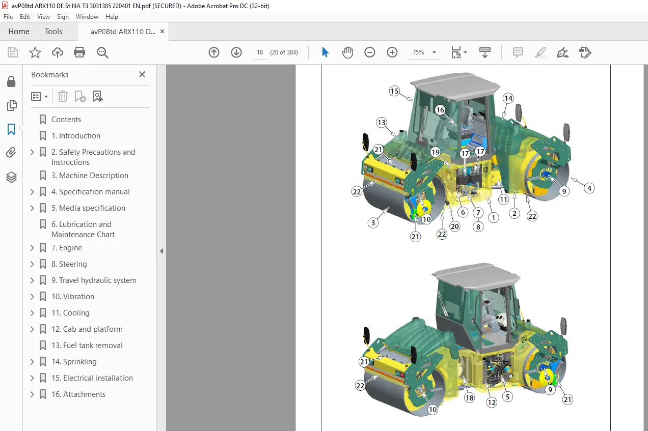
3 Machine Description 19
4 Specification manual 23
4 1 Basic specification 24
4 2 Machine dimension scheme 26
4 3 Technical data 30
5 Media specification 35
5 1 Engine oil 36
5 2 Fuel 37
5 3 Cooling liquid 37
5 4 Hydraulic oil 38
5 5 Gearbox oil 38
5 6 Lube grease 39
5 7 Glass washer fluid 39
5 8 Drum cooling liquid 39
5 9 Air Conditioning filling 39
5 10 Vibratory oil 39
5 11 Emulsion 39
5 12 Media 40
6 Lubrication and Maintenance Chart 41
7 Engine 47
7 1 Description of the engine and basic components 49
7 2 Technical data of the manufacturer 51
7 3 Troubleshooting 52
7 4 Engine removal 55
8 Steering 75
8 1 Description of basic components 77
8 2 Technical data of the manufacturer 78
8 3 Steering pump removal 79
8 4 Removal of the linear hydraulic motor of the steering and crab 84
8 4 1 Linear hydraulic motor – crab (90/45-125) 86
8 4 2 Linear hydraulic motor – steering (90/45-420) 88
8 4 3 Replacement of sealings of the linear hydraulic motor 90
8 5 Steering unit removal 94
8 6 Removal of the hydraulic tank 98
8 7 Steering wheel removal 103
8 8 Steering pillar removal 106
8 9 Removal of the steering joint from the machine 109
8 9 1 Removal of bearings of the steering joint 118
8 9 2 Removal of bearings of the arm 126
9 Travel hydraulic system 133
9 1 Description of basic components 135
9 2 Technical data of the manufacturer 135
9 3 Travel hydraulic motor removal 136
9 4 Travel gearbox removal 140
9 5 Travel pump removal 146
10 Vibration 153
10 1 Description of basic elements of vibration hydraulics 155
10 2 Technical data of the manufacturer 156
10 3 Removal of vibration hydraulic motor 157
10 4 Removal of vibration pump on front drum 164
10 5 Removal of vibration hydraulic pump from rear drum 168
10 6 Removal of drum from machine 172
10 7 Removal of vibrator bearings 182
10 8 Removal of flange bearings and damper plate 195
10 9 Removal of rubber-metals from drum 204
11 Cooling 211
11 1 Description of basic components of the cooling hydraulics 212
11 2 Technical data of the manufacturer 213
11 3 Removal of the cooling hydraulic motor and propeller 214
11 4 Cooling pump removal 220
11 5 Combined cooler disassembly 225
12 Cab and platform 235
12 1 Ball valve heating removal 237
12 2 Heating removal 240
12 3 Heating fan removal 244
12 4 Cab removal 248
12 5 Platform removal 254
12 6 Removal of rubber-metals of the platform 267
13 Fuel tank removal 277
14 Sprinkling 285
14 1 Sprinkling pump removal 286
14 2 Water tank removal 290
15 Electrical installation 297
15 1 Measurement technique 299
15 2 Safety and instruction 300
15 3 Fuse positioning 301
15 4 Display removal 302
15 5 Seat switch removal 305
15 6 Removal of the travel lever and switches 309
15 7 Adjust pulse sensor 314
15 8 Accumulators 317
15 9 Alternator 320
15 10 Starter 323
16 Attachments 327
16 1 Wiring diagram 328
16 2 Wiring diagram of chip spreader 334
16 3 Electric installations cable harnesses 337
16 4 Hydraulic system diagram ARX 110 366
16 5 Hydraulic system diagram ARX 110 HF 368
16 6 Hydraulic system diagram ARX 110 C 370
16 7 Hydraulic diagram of chip spreader 372
16 8 Check the tightening of bolted connections 374
16 9 List of spare parts specified in the publication 376
16 10 List of groups from spare parts catalog used in the publication 376
16 11 Error codes 377
Questions? Email us: [email protected]
https://vimeo.com/898274040?share=copy
S.V