Trusted Business
Verified & Licensed
Virus Free Files
100% Safe Downloads
Secure Payment
SSL Protected
Instant Delivery
Available Immediately
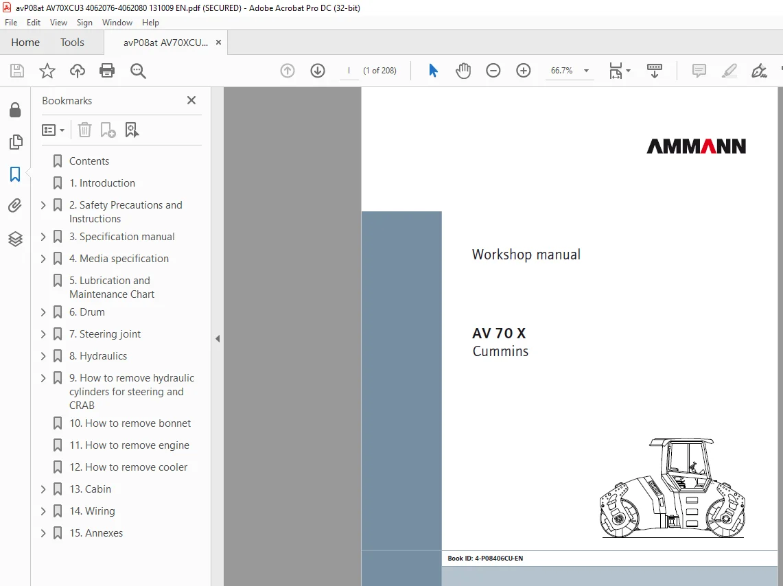
Ammann AV 70 X Tandem Roller Workshop Manual SN 4062076 PDF
$27.95
The Ammann AV 70 X Articulated Tandem Roller Cummins Tier 3 Workshop Manual (SN 4062076) is a detailed guide, offering precise instructions and specifications for efficient maintenance, ensuring optimal performance of this heavy-duty construction equipment.
Instant PDF Download
Available immediately
Save to Your Device
Download & keep forever
Antivirus Scanned
100% virus-free
Trusted Worldwide
175,000+ customers
Description
Ammann AV 70 X Articulated Tandem Roller Cummins Tier 3 Workshop Manual SN 4062076 – PDF DOWNLOAD
FILE DETAILS:
Ammann AV 70 X Articulated Tandem Roller Cummins Tier 3 Workshop Manual SN 4062076 – PDF DOWNLOAD
Language : English
Pages :208
Downloadable : Yes
File Type : PDF
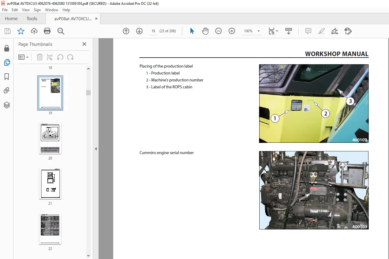
IMAGES PREVIEW OF THE MANUAL:
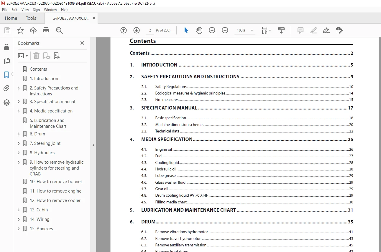
TABLE OF CONTENTS:
Ammann AV 70 X Articulated Tandem Roller Cummins Tier 3 Workshop Manual SN 4062076 – PDF DOWNLOAD
Contents...........................................................................  6
1.	Introduction ...................................................................  9
2.	Safety Precautions and Instructions............................................. 13
	2.1.	Safety Regulations........................................................ 14
		2.2.	Ecological measures & hygienic principles............................. 18
		2.3.	Fire measures......................................................... 19
3.	Specification manual............................................................ 21
	3.1.	Basic specification....................................................... 22
		3.2.	Machine dimension scheme.............................................. 24
		3.3.	Technical data........................................................ 26
4.	Media specification............................................................. 29
	4.1.	Engine oil................................................................ 30
		4.2.	Fuel.................................................................. 31
		4.3.	Cooling liquid........................................................ 32
		4.4.	Hydraulic oil ........................................................ 32
		4.5.	Lube grease .......................................................... 33
		4.6.	Glass washer fluid ................................................... 33
		4.7.	Gear oil.............................................................. 33
		4.8.	Drum cooling liquid AV 70 X HF........................................ 33
		4.9.	Filling media chart................................................... 34
5.	Lubrication and Maintenance Chart............................................... 35
6.	Drum............................................................................ 39
	6.1.	Remove vibrations hydromotor.............................................. 45
		6.2.	Remove travel hydromotor ............................................. 47
		6.3.	Remove auxiliary transmission......................................... 49
		6.4. 	Remove front drum.................................................... 51
		6.5.	Replace rubber mounting of drum....................................... 63
7. Steering joint.................................................................. 67
	7.1.	Preparation Work:......................................................... 69
		7.2.	Remove steering joint................................................. 76
		7.3.	Remove slewing ring bearing........................................... 81
		7.4.	Remove steering joint bearings........................................ 82
		7.5.	Install steering joint bearing........................................ 85
8. Hydraulics...................................................................... 89
	8.1.	Remove cooling hydromotor................................................. 91
		8.2.	Remove gear pump for steering ........................................ 93
		8.3.	Remove tandem pump for travel and vibrations.......................... 96
		8.3.1.	Vibration pump...................................................... 96
		8.3.2.	Pump for travel..................................................... 98
9.	How to remove hydraulic cylinders for steering and CRAB.........................101
	9.1.	Remove hydraulic cylinders for steering and CRAB..........................103
		9.2.	Replace packing material for steering or Crab hydraulic cylinders ....104
10.	How to remove bonnet...........................................................109
11.	How to remove engine...........................................................115
12.	How to remove cooler...........................................................125
13.	Cabin..........................................................................133
	13.1.	Remove heater............................................................135
		13.2.	Remove cooling air blowers...........................................137
		13.3.	Seat switch..........................................................140
		13.4.	Idle and parking brake positions sensor..............................142
		13.5.	LH control panel, backing horn sensor................................142
		13.6	 Seat platform........................................................145
		13.7.	Servosteering........................................................148
14.	Wiring.........................................................................151
	14.1.	Fuses....................................................................152
		14.2.	Storage battery......................................................154
		14.3.	Alternator...........................................................155
		14.4.	Starter Motor........................................................157
		14.5.	Layout of wiring elements on the Machine.............................160
15.	Annexes........................................................................163
	15.1.	Measure hydraulic circuit safety pressures ..............................164
		15.2.	How to adjust vibration frequency....................................167
		15.3.	How to adjust pulse sensors..........................................168
		15.4.	Adjust zero position of steering joint...............................169
		15.5.	Wiring Diagram.......................................................170
		15.6.	Electric installations cable harnesses...............................175
		15.7.	Hydraulic Diagram ...................................................196
		15.8.	Check the tightening of bolted connections...........................198
		15.9.	List of fixtures.....................................................200
		15.10.	Hand Signals........................................................202
Contact us: [email protected]
S.M