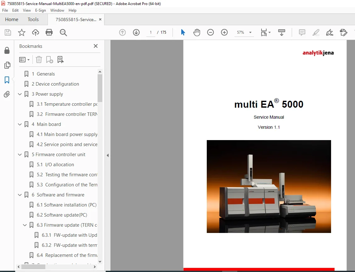
Analytik Jena multi EA 5000 Service Manual – PDF DOWNLOAD
Original price was: $95.00.$31.95Current price is: $31.95.
Detailed Analytik Jena multi EA 5000 service manual PDF (Version 1.1) for elemental analyzers. Covers multi EA 5000 firmware update instructions, elemental analyzer troubleshooting guide, temperature controller replacement, gas supply module repair, detector calibration procedures, and error evaluation. Essential for technicians handling combustion module temperature control and maintenance. 175-page high-quality guide for precise repairs.
Description
Analytik Jena multi EA 5000 Service Manual – PDF DOWNLOAD
Description
This Analytik Jena multi EA 5000 service manual PDF (Version 1.1) provides comprehensive instructions for servicing the multi EA 5000 elemental analyzer, focusing on configuration, testing, updates, and repairs to ensure accurate determination of elements like C, N, S, Cl. It includes detailed elemental analyzer troubleshooting guide for issues in power supply, main board, firmware controller, software/firmware updates, combustion module temperature control, gas supply module repair, measuring gas drying, sample dosing, and various detectors. Key procedures cover multi EA 5000 firmware update instructions for TERN controller and temperature units, temperature controller replacement with checks and settings, detector calibration procedures for UVFD, CLD, CI, and TC modules, and error evaluation using terminal programs and multiWin® logs.
The manual emphasizes safety, required tools, consumables, spare parts, and contact info for support, making it indispensable for maintaining optimal performance in analytical labs.
Neatly Categorized Table of Contents (extracted and formatted from pages 3-5):
- 1 Generals (Page 7)
- 2 Device configuration (Page 7)
- 3 Power supply (Page 8)
- 3.1 Temperature controller power supply (8)
- 3.2 Firmware controller TERN power supply (8)
- 4 Main board (Page 9)
- 4.1 Main board power supply (9)
- 4.2 Service points and service LEDs (10)
- 5 Firmware controller unit (Page 13)
- 5.1 I/O allocation (15)
- 5.2 Testing the firmware controller (17)
- 5.3 Configuration of the Terminal program (18)
- 6 Software and firmware (Page 34)
- 6.1 Software installation (PC) (34)
- 6.2 Software update (PC) (37)
- 6.3 Firmware update (TERN controller) (37)
- 6.3.1 FW-update with UpdateCenter of multiWin (38)
- 6.3.2 FW-update with terminal program (45)
- 6.4 Replacement of the firmware controller TERN (50)
- 7 Combustion module and temperature control (Page 51)
- 7.1 Temperature control for the valve heating and transfer line (52)
- 7.2 Temperature control for the furnace heating (52)
- 7.3 Temperature controller update (57)
- 7.3.1 Update with program SIOW.exe (57)
- 7.3.2 Update with UpdateCenter of multiWin (62)
- 7.4 Setting of the temperature controller (63)
- 7.5 Replacing the temperature controller (67)
- 7.5.1 Checking the furnace (67)
- 7.5.2 Replacing the thermocouple in the furnace (67)
- 7.5.3 Furnace replacement (68)
- 7.5.3.1 Removing of furnace (68)
- 7.5.3.2 Mounting of furnace (69)
- 8 Gas supply module (Page 71)
- 8.1 Checking the “high performance” gas box (73)
- 8.1.1 Setting the main oxygen (A1) flow rate in the “high performance” gas box (74)
- 8.2 Calibrating the internal MFM (77)
- 8.3 Gas box replacement (81)
- 8.4 Check of MFM (82)
- 8.5 Replacing the MFM (83)
- 8.1 Checking the “high performance” gas box (73)
- 9 Measuring gas drying unit (Page 84)
- 9.1 Membrane dryer unit (84)
- 9.1.1 Tightness check of the membrane dryer (85)
- 9.1.2 Replacement of the membrane dryer (86)
- 9.2 Auto-protection valve assembly (87)
- 9.2.1 Valve coupling with filter unit/ checking the filter (87)
- 9.2.2 Filter replacement (88)
- 9.2.3 Replacing the pneumatic seal (89)
- 9.2.4 Removing the complete valve coupling (91)
- 9.2.5 Check of the AP valve assembly (91)
- 9.1 Membrane dryer unit (84)
- 10 Sample dosing module (Page 92)
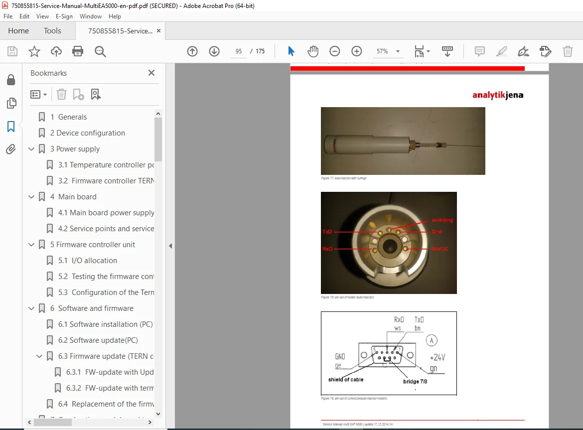
- 10.1 Auto-injector (94)
- 10.2 MMS 5000 (96)
- 10.2.1 Exchange of the main board (96)
- 10.2.2 Updating the firmware of the MMS sampler (96)
- 10.2.3 Replacing the main board of the MMS sampler (96)
- 10.2.4 Replacement of mechanical components (97)
- 10.2.5 Rack and syringe detection (97)
- 10.2.6 Check of the auto-sampler with service program (97)
- 10.2.7 Testing the interface sampler in simulation mode (MMS5000) with the service program (99)
- 10.3 ABD (100)
- 10.3.1 Block schema of ABD with multi EA® 5000 (101)
- 10.3.2 Test of the ABD with service program (101)
- 10.3.3 Testing the interface sampler in simulation mode (ABD) with the service program (103)
- 10.4 GSS module (105)
- 10.4.1 Structure of GSS module (105)
- 10.4.2 Testing the communication of GSS module with evaluation unit (multiWin®) (106)
- 10.4.3 Testing the GSS module with the service program (106)
- 10.4.4 Testing the interface sampler in simulation mode (GSS module) with the service program (108)
- 10.5 LPG module (LPG/GSS module) (109)
- 10.5.1 Testing the LPG module (LPG/GSS module) with components test of multiWin® (111)
- 10.5.2 Testing the LPG module (LPG/GSS module) with the service program (112)
- 10.5.3 Testing the interface sampler in simulation mode (LPG-/GSS module) with the service program (115)
- 10.5.4 Final test of LPG module (LPG/GSS module) (116)
- 11 Detectors (Page 117)
- 11.1 UVFD APSA370 (117)
- 11.1.1 Check of technical parameter and requirements APSA370 on its display (117)
- 11.1.2 Testing the communication of APSA370 with evaluation unit (multiWin®) (118)
- 11.1.3 Testing the APSA370 with the service program (118)
- 11.1.4 Testing the interface for APSA370 with the service program (simulation mode) (119)
- 11.2 UVFD5000 (120)
- 11.2.1 Check of technical parameter inside the components test (multiWin) (120)
- 11.2.2 Testing the UVFD5000 with the service program (121)
- 11.2.3 Testing the interface for UVFD5000 with the service program (simulation mode) (123)
- 11.3 CLD APNA370 (125)
- 11.3.1 Check of technical parameter and requirements APNA370 on its display (125)
- 11.3.2 Testing the communication of APNA370 with evaluation unit (multiWin®) (126)
- 11.3.3 Testing the APNA370 with the service program (126)
- 11.3.4 Testing the interface for APNA370 with the service program (simulation mode) (128)
- 11.4 CLD5000 (129)
- 11.4.1 Check of technical parameter inside the components test (multiWin) (129)
- 11.4.2 Testing the CLD5000 with the service program (130)
- 11.4.3 Testing the interface for CLD5000 with the service program (simulation mode) (132)
- 11.5 CI module (133)
- 11.5.1 Measuring principle and conditions (133)
- 11.5.2 Measuring cell “high sensitive” (133)
- 11.5.3 Measuring cell “sensitive” (135)
- 11.5.4 Temperature stabilization of the measuring cell (136)
- 11.5.5 Mixer control (138)
- 11.5.6 Measuring cell detection (139)
- 11.5.7 Testing the coulometer electronics (141)
- 11.5.7.1 Testing the “high sensitive” cells (142)
- 11.5.8 Power supply (144)
- 11.5.9 Control electronics (145)
- 11.5.10 Checking the CI module >>> components test (148)
- 11.5.10.1 Checking the CI module >>> Service program (test mode) (149)
- 11.5.10.2 Checking the CI module >>> Service program (simulation mode) (149)
- 11.6 TC module (150)
- 11.6.1 Structure of the TC-module (151)
- 11.6.2 Checking the NDIR optics (hardware) (152)
- 11.6.3 Checking the NDIR optics >>> components test (153)
- 11.6.4 Checking the NDIR optics >>> Service program (test mode) (153)
- 11.6.5 Checking the NDIR optics >>> Service program (simulation mode) (154)
- 11.6.6 Replacing the NDIR optics (154)
- 11.1 UVFD APSA370 (117)
- 12 Error evaluation (Page 155)
- 12.1 Error evaluation with Terminal program (display mode) (155)
- 12.2 Error evaluation with multiWin® (161)
- 12.2.1 Components test (161)
- 12.2.2 System information (162)
- 12.2.3 Record of LOG-files (163)
- 12.2.3.1 MultiWin_info.txt (165)
- 12.2.3.2 multiWin_Error.LOG (165)
- 12.2.3.3 <multiWin_Comm.log> (168)
- 12.3 Error messages (170)
- 13 Consumables (Page 173)
- 14 Spare parts (Page 173)
- 15 Recommended tools and measuring instruments (Page 174)
- 16 Contact (Page 175)
No separate bookmarks or index noted beyond the TOC, but the structure supports easy navigation for elemental analyzer troubleshooting guide, multi EA 5000 firmware update instructions, temperature controller replacement, gas supply module repair, and detector calibration procedures.
File Details
- Manual Name: multi EA 5000 Service Manual
- Models Covered: multi EA 5000
- Year: N/A
- Manual PDF Quality: High (clear text, diagrams, and tables)
- No of Pages: 175