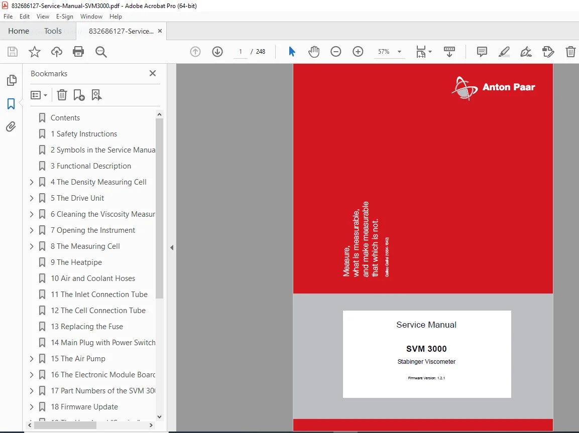
Anton Paar SVM 3000 Stabinger Viscometer Service Manual Repair Maintenance PDF
Original price was: $95.00.$18.95Current price is: $18.95.
Complete factory service manual for Anton Paar SVM 3000 Stabinger Viscometer firmware version 1.2.1. Comprehensive technical documentation includes density measuring cell service, drive unit maintenance, oscillating U-tube replacement, electronic module boards, troubleshooting procedures, calibration protocols, and preventive maintenance schedules. Features detailed diagrams, part numbers, firmware updates, and diagnostic procedures. Essential professional reference for laboratory technicians servicing precision viscosity and density analyzers.
Description
Anton Paar SVM 3000 Stabinger Viscometer Service Manual Repair Maintenance – PDF DOWNLOAD
DESCRIPTION
This is the complete official Anton Paar SVM 3000 Stabinger Viscometer Service Manual (Document C18IB03-C.fm, August 2004) for professional viscosity and density measurement instruments. This comprehensive factory service manual provides professional-grade maintenance, troubleshooting, calibration, and repair information for authorized service technicians and qualified laboratory personnel servicing this advanced analytical instrument.
Equipment Covered by This Service Manual
Anton Paar SVM 3000 Stabinger Viscometer:
- Firmware Version: 1.2.1
- Measurement Principle: Stabinger principle (rotating viscometer with density measurement)
- Application: Kinematic viscosity and density measurement
- Markets: Petroleum, chemical, pharmaceutical, food & beverage laboratories
Manufacturer:
- Anton Paar GmbH
- Anton-Paar-Str. 20
- A-8054 Graz, Austria – Europe
- Tel: +43 316 257-0
Equipment Type:
- Laboratory analytical instrument
- Precision viscometer
- Density analyzer
- Dual-parameter measurement system
Applications:
- Kinematic viscosity measurement
- Dynamic viscosity calculation
- Density determination
- Quality control
- R&D applications
- Compliance testing (ASTM, ISO standards)
Complete Manual Contents (248 Pages)
This Anton Paar SVM 3000 service manual PDF is organized into comprehensive chapters for systematic service and repair:
TABLE OF CONTENTS OVERVIEW
Chapter 1: Safety Instructions (Page 9)
- Service technician responsibilities
- Health and safety regulations
- Sample handling precautions
- Equipment safety requirements
Chapter 2: Symbols in Service Manual (Page 11)
- Warning symbols
- Caution symbols
- Note indicators
- Safety icons
Chapter 3: Functional Description (Page 13)
- System overview
- Measurement principles
- Component interaction
- Operating theory
CHAPTER 4: THE DENSITY MEASURING CELL (PAGES 15-24)
4.1 Removing the Oscillating U-tube (Page 16)
- Disassembly procedure
- Tool requirements
- Safety precautions
- Step-by-step instructions
4.2 Seals (Pages 19-21)
4.2.1 Instruments with KALREZ Seal Rings:
- KALREZ seal specifications
- Replacement procedure
- Installation techniques
- Torque requirements
4.2.2 Instruments with Viton Seals and Jackets:
- Viton seal characteristics
- Jacket installation
- Seal inspection criteria
- Replacement guidelines
4.2.3 Instruments with PTFE Covered Viton Seals:
- PTFE-covered seal assembly
- Installation procedures
- Quality verification
4.3 Mounting the Oscillating U-tube (Page 22)
- Installation sequence
- Alignment procedures
- Torque specifications
- Leak testing
4.4 Adjustment, Calibration (Page 24)
- Density calibration
- Reference standards
- Calibration verification
- Acceptance criteria
CHAPTER 5: THE DRIVE UNIT (PAGES 25-46)
5.1 Replacing Drive Shaft and Seals – Preparations (Page 25)
- Required tools
- Safety precautions
- Preliminary steps
5.2 Removal of Drive Shaft and Seal Rings (Page 26)
- Disassembly procedure
- Seal extraction
- Component inspection
5.3 Checking the Drive Shaft (Page 27)
- Visual inspection
- Wear assessment
- Measurement verification
- Replacement criteria
5.4 Replacing Glands and Cleaning Bearing/Sealing Unit (Page 28)
- Gland removal
- Cleaning procedures
- Solvent selection
- Ultrasonic cleaning
5.5 Reassembling the Bearing and Sealing Unit (Page 32)
- Assembly sequence
- Seal installation
- Lubrication points
- Torque specifications
5.6 Mounting the Drive Shaft (Page 34)
- Installation procedure
- Alignment verification
- Final assembly
5.7 Adjustment of Drive Shaft Seal (Page 37)
- Seal adjustment procedure
- Leak testing
- Performance verification
5.8 Bearing and Sealing Retrofit Unit (Pages 38-40)
5.8.1 Replacing Bearing/Sealing Unit by Retrofit Unit:
- Retrofit procedure
- Component compatibility
- Installation sequence
5.8.2 Replacing PTFE-Seal of Retrofit Unit:
- Seal replacement
- Installation technique
5.9 Replacing the Measuring Motor (Pages 41-46)
- Motor removal
- Electrical disconnection
- New motor installation
- Alignment procedures
- Testing and verification
CHAPTER 6: CLEANING THE VISCOSITY MEASURING CELL (PAGES 47-54)
6.1 Disassembling the Measuring Rotor (Pages 47-48)
- Rotor removal procedure
- Component identification
- Handling precautions
6.2 Reassembling the Measuring Rotor (Page 49)
- Assembly sequence
- Alignment verification
- Installation checks
6.3 Adjusting Position of Drive Unit and Drive Shaft (Pages 50-54)
- Position adjustment procedure
- Measurement techniques
- Optimization criteria
- Final verification
CHAPTER 7: OPENING THE INSTRUMENT (PAGES 55-58)
7.1 Removing the Top Cover (Pages 55-56)
- Cover removal procedure
- Fastener locations
- Safety precautions
7.2 Replacing the Splash Guard (Page 57)
- Splash guard removal
- Installation procedure
7.3 Removing the Base Panel (Pages 57-58)
- Panel removal steps
- Access to internal components
CHAPTER 8: THE MEASURING CELL (PAGES 59-70)
8.1 Replacing the Measuring Cell Block (Pages 60-66)
- Cell block removal
- Electrical disconnection
- Fluidic disconnection
- New block installation
- System verification
8.2 Replacing the Measuring Cell Assembly (Pages 67-70)
- Complete assembly replacement
- Connection procedures
- Testing and calibration
CHAPTERS 9-15: COMPONENT REPLACEMENT
Chapter 9: The Heatpipe (Pages 71-72)
- Heatpipe function
- Replacement procedure
- Thermal interface
Chapter 10: Air and Coolant Hoses (Pages 73-76)
- Hose routing diagrams
- Replacement procedures
- Leak testing
Chapter 11: Inlet Connection Tube (Pages 77-78)
- Tube removal
- Installation procedure
Chapter 12: Cell Connection Tube (Pages 79-80)
- Connection tube service
- Seal replacement
Chapter 13: Replacing the Fuse (Pages 81-82)
- Fuse location
- Rating specifications
- Replacement procedure
Chapter 14: Main Plug with Power Switch (Pages 83-86)
- Power switch assembly
- Replacement procedure
- Electrical safety
Chapter 15: The Air Pump (Pages 87-94)
15.1 Replacing Air Pump Membranes:
- Membrane removal
- Installation procedure
- Performance testing
15.2 Replacing the Air Pump:
- Complete pump replacement
- Mounting procedure
- Hose connections
CHAPTER 16: THE ELECTRONIC MODULE BOARDS (PAGES 95-132)
16.1 CPU-Board (Pages 95-102)
16.1.1 Replacing the CPU2-Board:
- Board removal procedure
- Cable disconnection
- New board installation
- Configuration
16.1.2 Replacing Batteries on CPU2-Board:
- Battery location
- Replacement procedure
- Data preservation
16.1.3 Retrofitting SVM 3000 to CPU3-Board:
- Upgrade procedure
- Hardware modifications
- Firmware update
- Testing
16.2 Replacing S-Bus-Interface Board (Page 103)
- Interface board service
- Connection procedures
16.3 Replacing the PVR-Board (Page 104)
- PVR board function
- Replacement steps
16.4 Replacing the SPS-II-Board (Pages 105-106)
- Power supply board
- Safety precautions
- Installation
16.5 The MEF2-Board (Pages 107-110)
16.5.1 Replacing the MEF2-Board:
- Measurement electronics
- Replacement procedure
16.5.2 Exchange Connection between Cell Block and MEF2-Board:
- Cable replacement
- Signal integrity
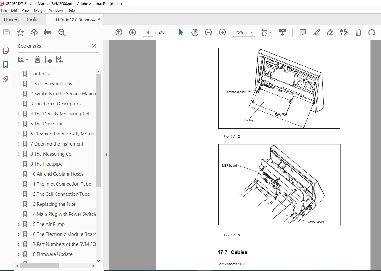
16.6 Replacing Display and Keyboard (Pages 111-114)
- Display removal
- Keyboard replacement
- Connection verification
16.7 Cable Connections (Page 115)
- Cable routing diagrams
- Connector locations
- Pin assignments
16.8 Diagnosis on Electronic Boards (Pages 116-132)
- Diagnostic procedures
- Testing methods
- Fault isolation
- Signal measurements
- Voltage checks
CHAPTER 17: PART NUMBERS (PAGES 133-142)
17.1 Accessories (Page 133)
- Optional accessories
- Part numbers
17.2 Consumables (Page 134)
- Seals and O-rings
- Filters
- Cleaning supplies
17.3 Hoses (Page 135)
- Hose specifications
- Part numbers
- Lengths
17.4 Service Tools (Page 136)
- Specialized tools
- Tool part numbers
17.5 Spare Parts (Pages 136-139)
- Complete spare parts list
- Part numbers
- Descriptions
17.6 Electronic Module Boards (Page 140)
- Board part numbers
- Firmware versions
17.7 Cables (Page 141)
- Cable assemblies
- Part numbers
17.8 Connector Pin Assignments (Page 142)
- Serial interface pinout
- Printer cable pinout
CHAPTER 18: FIRMWARE UPDATE (PAGES 143-146)
18.1 Firmware Update for CPU2-Board (Pages 143-144)
- Update procedure
- File requirements
- Verification
18.2 Firmware Update for CPU3-Board (Pages 145-146)
- Update procedure
- Modern firmware
- Testing
CHAPTER 19: THE USER LEVEL “SERVICE” (PAGES 147-176)
19.1 In the Measuring Window (Pages 148-151)
- Service mode access
- Display functions
19.2 The Service Menu (Pages 152-176)
19.2.1 FW Version Numbers:
- Firmware identification
- Version checking
19.2.2 Protocol Mode (Pages 155-166):
- Visco Average Values – Viscosity data logging
- Motor High Speed (measuring speed)
- Motor Low Speed (filling speed)
- Temperature Control – Thermal management
- Osc. Burn-In Cycle – Oscillator conditioning
19.2.3 Device Test (Pages 167-172):
- Comprehensive system test
- Component verification
19.2.4 Cell Test (Pages 173-175):
- Measuring cell diagnostics
19.2.5 Factory Cell Test (Page 176):
- Factory-level testing
CHAPTER 20: ERROR MESSAGES (PAGES 177-178)
Complete Error Code List:
- Error descriptions
- Possible causes
- Corrective actions
- Error code reference
CHAPTER 21: TROUBLESHOOTING (PAGES 179-196)
21.1 Measuring (Pages 179-184)
- Viscosity measurement problems
- Density measurement issues
- Temperature stability
- Sample-related problems
21.2 Other Problems (Pages 185-190)
- Mechanical issues
- Electrical problems
- Communication failures
- Software errors
21.3 Error Messages (Pages 191-194)
- Detailed error analysis
- Diagnostic procedures
- Resolution steps
21.4 Warnings (Pages 195-196)
- Warning messages
- Preventive actions
CHAPTERS 22-23: ADVANCED PROCEDURES
Chapter 22: How to Retrieve Lost Passwords (Pages 197-198)
- Password recovery
- Access restoration
Chapter 23: Communication via Serial Interface (Pages 199-214)
23.1 Terminal Program:
- Communication setup
- Terminal settings
23.2 AP SoftPrint for SVM:
- Software interface
- Data export
23.3 Serial Commands (Pages 202-214):
- Complete command set
- Command syntax
- Parameter programming
- Data retrieval
- Remote control
APPENDICES (PAGES 215-240)
Appendix A: Improvements (Pages 215-216)
- Design changes
- Upgrades
- Modifications
Appendix B: Malfunction Report (Pages 217-220)
- Service report form
- Problem documentation
- Contact information
Appendix C: Maintenance and Calibration Instruction/Record (Pages 221-232)
- Maintenance schedule
- Calibration log
- Service history
- Performance records
Appendix D: Menu Structure User Level “Service” (Pages 233-238)
- Complete menu tree
- Navigation guide
Appendix E: Feedback Form (Pages 239-240)
- User feedback
- Manual improvement suggestions
Index (Pages 241-246) Notes (Pages 247-248)
Key Features
Stabinger Viscometer Technology:
- Rotating measuring principle
- Simultaneous viscosity and density
- Temperature control system
- High precision measurement
- Wide measuring range
Comprehensive Service Coverage:
- Density measuring cell
- Drive unit and motor
- Electronic boards
- Pneumatic system
- Temperature control
- Software/firmware
Professional Documentation:
- Step-by-step procedures
- Detailed illustrations
- Part number references
- Troubleshooting guides
- Diagnostic tools
Professional Service Features
Factory Documentation:
- Published by Anton Paar GmbH, Graz, Austria
- Copyright © 2004
- Current through August 2004
- Continuous product support
Comprehensive Coverage:
- Complete disassembly procedures
- Electronic diagnostics
- Calibration protocols
- Firmware updates
- Serial communication
Visual Aids:
- Component photographs
- Exploded view diagrams
- Circuit board layouts
- Hose routing diagrams
- Menu structure trees
Who Should Use This Manual?
This Anton Paar service documentation is essential for:
- Authorized Anton Paar service technicians
- Laboratory instrument specialists
- Biomedical equipment technicians
- Quality control laboratory staff
- Petroleum testing laboratory technicians
- Chemical analysis professionals
- Pharmaceutical QC personnel
Required Qualifications:
- Anton Paar training (preferred)
- Laboratory instrument experience
- Electronic troubleshooting skills
- Mechanical aptitude
- Precision measurement knowledge
- Safety awareness
Important Service Notes
Authorized Service: This is precision analytical equipment requiring:
- Qualified service personnel
- Proper calibration procedures
- Genuine Anton Paar parts
- Documentation of service
- Performance verification
Safety Critical:
- Sample handling precautions
- Chemical compatibility
- Electrical safety
- Moving parts hazards
- Temperature hazards
Intellectual Property:
- Anton Paar proprietary information
- Copyright protected
- No unauthorized reproduction
- Trade secrets protected
Calibration Requirements:
- Regular calibration verification
- Reference standards
- Traceability requirements
- Quality system compliance
Sample Considerations:
- Chemical compatibility
- Temperature range
- Viscosity range
- Safety data sheets
FILE DETAILS
| Attribute | Details |
|---|---|
| Manual Name | SVM 3000 Stabinger Viscometer Service Manual |
| Document Number | C18IB03-C.fm |
| Publication Date | August 2004 |
| Firmware Version | 1.2.1 |
| Equipment Model | Anton Paar SVM 3000 |
| Equipment Type | Stabinger Viscometer (Viscosity & Density Analyzer) |
| Manufacturer | Anton Paar GmbH, Graz, Austria |
| Application | Laboratory Analytical Instrument |
| Manual Type | Factory Service, Repair & Calibration Manual |
| File Format | PDF (A4 size pages) |
| File Size | ~4.3 MB |
| Total Pages | 248 pages |
| PDF Quality | Factory manual with detailed illustrations |
| Language | English |
| Creator | FrameMaker 7.0 |
| Copyright | © 2004 Anton Paar GmbH |