Atari CX-5200 Game Console Field Service Manual PDF
Original price was: $95.00.$18.95Current price is: $18.95.
Official Atari CX-5200 field service manual with complete repair and diagnostic procedures for 4-port and 2-port game console models. Includes circuit theory, full schematics, PCB silkscreens, diagnostic flowcharts, and component-level troubleshooting guides. Covers MPU, ANTIC, GTIA, and POKEY chips plus CX52 game controller repair procedures. Essential technical documentation for vintage gaming console restoration and professional electronics repair technicians servicing classic Atari systems.
Description
Atari CX-5200 Game Console Field Service Manual Repair Guide 1983 PDF DOWNLOAD
Description
Atari CX-5200 Game Console – Official Field Service Manual
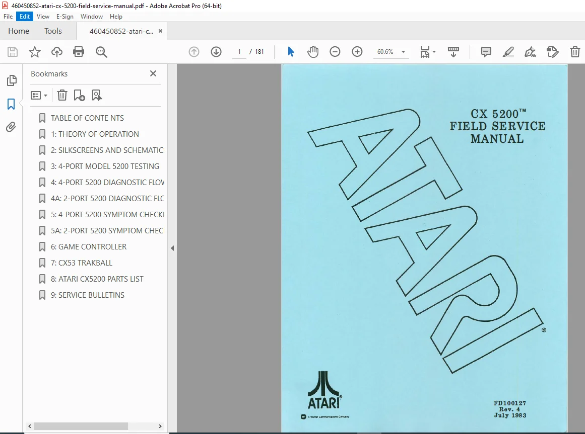
Complete official Atari field service documentation for the legendary CX-5200 SuperSystem game console. This 181-page technical manual provides comprehensive repair procedures, circuit analysis, diagnostic testing protocols, and component-level troubleshooting for both 4-port and 2-port console models.
File Details
- Manual Name: Atari CX-5200 Field Service Manual
- Models Covered: 4-Port Model 5200, 2-Port Model 5200, CX52 Game Controllers, CX53 Trakball
- Year: July 1983 Edition (Revision 4)
- PDF Quality: High-quality scanned original Atari documentation
- Total Pages: 181 pages
- Manual Code: FDI00127 Rev. 4
Complete Manual Contents
Section 1: Theory of Operation (Pages 1-1 to 1-8)
Console Overview & Architecture
- Model 5200 Console Description
- 4-Port Universal PCB architecture
- 2-Port Universal PCB differences
- Hardware configuration comparison
- Physical Components:
- Outer case construction
- RF shield specifications
- Printed circuit board layout
- Channel 2-3 switch interface
- Future development access port
Integrated Circuit Theory
- Microprocessor Chip (MPU)
- Complete pin assignments diagram
- Signal descriptions and functions
- Clock timing specifications
- Address and data bus architecture
- ANTIC (Alphanumeric Television Interface Controller)
- Pin configuration details
- Display list processor operation
- DMA controller functions
- Video timing generation
- GTIA (Graphic Television Interface Adaptor)
- Pin assignments and functions
- Color generation circuits
- Player-missile graphics
- Collision detection systems
- POKEY (Pot Keyboard Integrated Circuit)
- Pin configuration diagrams
- Audio tone generation
- Keyboard scanning circuits
- Paddle/joystick input processing
- Serial I/O operations
Peripheral Components
- Switchbox Interface
- RF modulator circuits
- Channel selection mechanism
- Signal routing diagrams
- Game Controller Architecture
- Joystick interface circuits
- Keypad matrix scanning
- Fire button detection
- Potentiometer input processing
Section 2: Schematics & Silkscreens (Pages 2-1 to 2-29)
Complete Circuit Diagrams:
4-Port Model Schematics:
- 5200 Motherboard complete schematic (3 large sheets)
- 4-Port detailed schematic (4 sheets covering all circuits)
- 4-Port PCB silkscreen (component placement)
2-Port Model Schematics:
- 5200 2-Port complete schematic (5 detailed sheets)
- 2-Port PCB silkscreen diagram
- Circuit differences from 4-port model
Controller Schematics:
- CX52 Game Controller circuit diagram
- CX53 Trakball keypad schematic
- CX53 Trakball complete circuit
- Trakball PCB silkscreen
All schematics include:
- Component values and part numbers
- IC pin connections
- Power supply routing
- Signal path tracing
- Test point locations
Section 3: 4-Port Model 5200 Testing (Pages 3-1 to 3-10)
Equipment Requirements
- Diagnostic cartridge specifications (Version 1.1)
- Required test equipment list
- Test setup procedures
Diagnostic Testing Procedures:
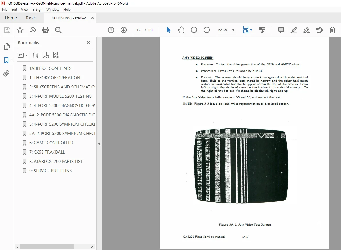
Video Display Tests:
- Power-up screen verification
- Solid colored screen diagnosis
- Vertically lined screen troubleshooting
- Snowy screen analysis
- Warped/ragged picture correction
- Color bar test procedures
- Gray bar test protocols
System Component Tests:
- RAM Test – Memory diagnostic procedures
- ROM Verify – Program memory validation
- Port Test – Controller interface verification
- Tone Test – Audio system diagnostics
- POKEY Adjust – Audio chip calibration
Test Features:
- Initialization sequences
- Error summary reporting
- Step-by-step test execution
- Pass/fail criteria for each test
Section 3A: 2-Port Model 5200 Testing (Pages 3A-1 to 3A-10)
Diagnostic Procedures Specific to 2-Port Models:
- Modified test sequences for 2-port architecture
- OS ROM verification procedures
- POKEY port testing protocols
- POKEY softfire test procedures
- RAM diagnostic routines
- Adjusted tone test procedures
Section 4: 4-Port Diagnostic Flowcharts (Pages 4-1 to 4-23)
Systematic Troubleshooting Process:
- Overview of Diagnostic Approach
- Symptom-based diagnosis methodology
- Systematic fault isolation procedures
- Swap-Out Procedure
- Component replacement sequences
- Testing after each replacement
- Verification protocols
- Replace in Order Guidelines
- Prioritized component replacement list
- Statistical failure analysis data
- Atari Repair Hotline Information
- Technical support resources
- Escalation procedures
Detailed Flowcharts Include:
- Video failure diagnosis trees
- Audio problem isolation
- Controller interface troubleshooting
- Power supply fault analysis
- Complete step-by-step decision trees
Section 4A: 2-Port Diagnostic Flowcharts (Pages 4A-1 to 4A-23)
Modified flowcharts for 2-port model including:
- Architecture-specific troubleshooting paths
- Component swap sequences for 2-port boards
- Diagnostic differences from 4-port models
Section 5: 4-Port Symptom Checklist (Page 5-1)
Quick-reference troubleshooting guide organized by symptoms:
- No power conditions
- Video display problems
- Audio failures
- Controller issues
- Cartridge interface problems
Section 5A: 2-Port Symptom Checklist (Page 5A-1)
Symptom-based diagnosis specific to 2-port architecture
Section 6: Game Controllers (Pages 6-1 to 6-13)
CX52 Controller Detailed Coverage:
Controller Components:
- Joystick Mechanism
- Self-centering design
- Potentiometer operation
- Mechanical assembly details
- Keypad Matrix
- 12-key layout and scanning
- Contact mechanism
- Electrical characteristics
- Fire Buttons
- Switch type and operation
- Debouncing circuits
- Start/Pause/Reset Buttons
- Function descriptions
- Circuit integration
Controller Testing Procedures:
- Testing with Console
- Port verification methods
- Button response testing
- Joystick range verification
- Standalone Testing without Console
- Resistance measurements
- Continuity checks
- Potentiometer testing
Controller Repair:
- Common Failures & Solutions
- Joystick drift problems
- Non-responsive buttons
- Keypad contact issues
- Cable/connector failures
- POT Arm Alignment Procedure
- Step-by-step alignment instructions
- Calibration techniques
- Adjustment specifications
- Complete Disassembly/Assembly Instructions
- Case opening procedures
- Component removal sequence
- Reassembly guidelines
- Screw locations and types
CX52 Game Controller Schematic – Complete circuit diagram
Section 7: CX53 Trakball (Page 7-1)
Technical information for Atari’s trackball controller accessory
Section 8: Parts List (Pages 8-1 to 8-11)
Comprehensive Component Catalog:
- Integrated Circuits
- Atari part numbers
- IC type specifications
- Replacement guidelines
- Discrete Components
- Resistor values and tolerances
- Capacitor specifications
- Transistor part numbers
- Diode specifications
- Mechanical Parts
- Case components
- Hardware specifications
- Switch assemblies
- RF Components
- Modulator parts
- Coils and transformers
- RF shielding components
- Connectors & Cables
- Controller port connectors
- Power supply connectors
- Internal cable assemblies
Ordering Information:
- Atari part numbering system
- Replacement part availability
- Cross-reference information
Section 9: Service Bulletins (Page 9-1)
Engineering change notices and field service updates
Why This Manual is Essential
For Vintage Gaming Console Collectors:
- Authentic Atari factory service documentation
- Complete repair procedures for restoration projects
- Original schematics for authentic restorations
- Controller repair extends gaming system life
For Electronics Repair Technicians:
- Component-level troubleshooting eliminates guesswork
- Diagnostic flowcharts provide systematic repair approach
- Full schematics enable circuit-level repairs
- Parts lists facilitate component sourcing
For Retro Gaming Enthusiasts:
- Keep classic Atari 5200 systems operational
- Repair controllers instead of expensive replacements
- Understanding of system architecture
- Preservation of gaming history
For Computer History Preservationists:
- Technical documentation of early 1980s gaming technology
- Insight into Atari’s design philosophy
- Custom chip architecture details (ANTIC, GTIA, POKEY)
- Historical reference for gaming console evolution
Technical Documentation Highlights
✓ Both Model Variants Covered – Complete coverage of 4-port and 2-port console versions in one manual
✓ Custom Chip Documentation – Detailed pin assignments and theory for Atari’s proprietary ICs
✓ Full-Size Schematics – Professional-quality circuit diagrams with all component values
✓ Diagnostic Cartridge Procedures – Step-by-step testing using official Atari diagnostic tools
✓ Controller Repair Section – Extensive coverage of CX52 controller disassembly and repair
✓ Flowchart Troubleshooting – Visual diagnostic guides for efficient fault isolation
✓ Complete Parts Lists – Atari part numbers for component ordering
Instant Digital Access
- Immediate PDF Download – Start repairs today
- Searchable Format – Find specific circuits or procedures quickly
- Print Selected Pages – Create shop copies of frequently used sections
- Zoom High-Resolution Schematics – View fine circuit details
- Permanent Reference – Save to your vintage gaming repair library
Download your Atari CX-5200 field service manual now and access 181 pages of official factory repair documentation—restore classic gaming consoles to working condition, repair valuable controllers, and preserve gaming history with authentic Atari technical information from 1983!
Reasoning: This is official factory service documentation for a classic 1980s gaming console with significant collector and retro gaming enthusiast interest. The 181-page manual includes comprehensive schematics, diagnostic procedures, and controller repair information for the Atari 5200 SuperSystem. While specialized, the vintage gaming repair market is active, and this documentation enables both professional repairs and hobbyist restoration projects. The nostalgic value, technical completeness, and continued use of Atari 5200 consoles in retro gaming communities justify mid-range pricing for this historical technical resource.