Atlas Copco ECM 585 II Drill Rig Service Training Manual Hydraulic & Electrical PDF
Original price was: $120.00.$25.95Current price is: $25.95.
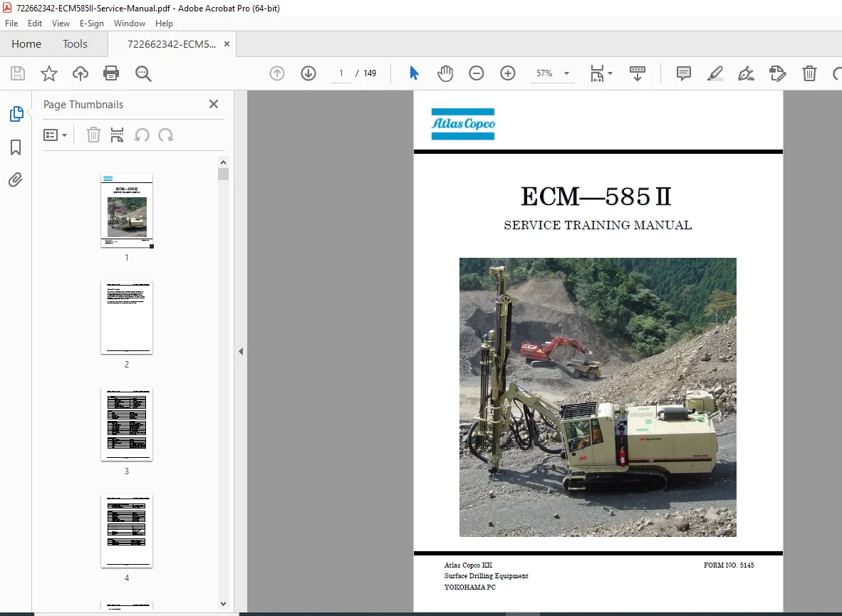
Official Atlas Copco ECM 585 II crawler drill rig service training manual (Form No. 5145). Covers general specs, hydraulic system, drill pilot circuit, PAJ anti-jam valve block, tram circuit, ARC & dust collector circuits, air compressor, cooling system, and full electrical circuit. Powered by Cummins QSB 6.7C Tier III engine with HC109RP drifter. Essential for field technicians servicing Atlas Copco ECM 585 surface drill rigs. Instant PDF download – 149 pages of factory technical content.
Description
Atlas Copco ECM 585 II Drill Rig Service Training Manual Hydraulic & Electrical PDF DOWNLOAD
Description
Atlas Copco ECM 585 II Surface Drill Rig – Official Service Training Manual
This is the official Atlas Copco factory service training manual for the ECM 585 II crawler drill rig — a comprehensive Atlas Copco ECM 585 hydraulic, pneumatic, and electrical systems guide for qualified field service technicians and drill rig operators. Covering all 10 technical sections from general machine specifications to advanced electrical interlock circuits, this manual is the definitive reference for diagnosing, adjusting, and servicing the ECM 585 II surface drilling equipment.
📋 File Details
| Detail | Info |
|---|---|
| Manual Name | ECM 585 II Service Training Manual |
| Form Number | Form No. 5145 |
| Manufacturer | Atlas Copco KK – Surface Drilling Equipment, Yokohama PC |
| Models Covered | Atlas Copco ECM 585 II |
| Year | 2007 |
| PDF Quality | High quality, text-searchable |
| Total Pages | 149 pages |
| File Format |
📚 Machine Specifications at a Glance
| System | Specification |
|---|---|
| Engine | Cummins QSB 6.7C Tier III, 220 hp (164 kW) @ 2,200 rpm |
| Drifter Model | HC109RP Reverse Percussion |
| Hole Diameter | 2½ to 4 in (64–104 mm) |
| Drifter Rotation Speed | 0–160 rpm |
| Max Rotation Torque | 903 lb-ft (1,225 N-m) |
| Impact Frequency | 3,000 BPM (50 Hz) |
| Impact Energy | 25.8 hp (19.2 kW) |
| Compressor | GHH-Rand Rotary Screw – 270 cfm @ 140 psi (9.7 bar) |
| Feed Force/Pullback | 4,409 lbf (19.9 kN) |
| Drifter Travel | 13 ft 11 in (4,250 mm) |
| Fuel Tank | 106 gal (400 L) |
| Hydraulic Oil Tank | 53 gal (200 L) |
| Electrical System | 24V DC |
| Machine Weight | 30,860 lb (14,000 kg) |
| Max Gradeability | 30° |
| Tram Speed | 0–2.1 mph (0–3.4 kph) |
| Dust Collector Capacity | 989 cfm (28 m³/min) |
| Rod System | Modular 6-rod x 12 ft carousel, T45 standard / T38 optional |
📚 Table of Contents
Section 1 – General Information
- Machine overview – open loop, open center hydraulic system
- Drifter specifications (HC109RP)
- Engine specifications (Cummins QSB 6.7C Tier III)
- Boom and guide specifications – feed force, feed speed, guide extension
- Compressor specifications (GHH-Rand rotary screw)
- General specifications – gradeability, ground clearance, track oscillation, grouser width
- Dust collector specifications
- Shipping dimensions and weight
- Standard equipment list – ROPS/FOPS cab, air conditioning, STRATA-SENSE® II anti-jam, auto rod changer, auto thread greaser, digital angle indicator
- Optional equipment – pressure test kit, 38mm rod handling system, 3-axis angle indicator, extended warranty
Section 2 – Hydraulic System
- System overview – open loop, open center, power beyond circuit
- Five-pump hydraulic system – all positive displacement gear pumps (Pumps 1–5, individual circuit functions)
- Three-section gear pump mounting and individual replaceability
- Relief valve adjustment procedure – with fluid at operating temperature (45–50°C / 115–125°F)
- No.1 Relief Valve – left hand tramming & drifter rotation (250 bar / 3,625 PSI)
- Additional relief valve settings with test port locations
- Hydraulic system circuit diagrams
Section 3 – Drill Pilot Circuit
- Pilot circuit overview – pilot pressure supply from Pump #4 at 30 kg/cm² (425 PSI)
- Drill/Tram selector valve operation
- 4-bank solenoid valve (82) operation in drill mode
- Forward drilling (coupling) sequence – drifter forward feed, percussion, rotation
- Uncoupling (decoupling) sequence – reverse rotation, drifter retraction
- Percussion switch in super rotation mode – oil flow from Pump #1 through flow divider to percussion and rotation valves
- Shuttle valve block operation
- Pilot circuit schematic diagrams
Section 4 – PAJ (Progressive Anti-Jam) Valve Block
- Main pump oil flow explanation (all control levers in neutral)
- Pump 1 (red) – left tram, super rotation, fast feed & percussion spool (250 bar)
- Pump 2 (green) – right tram, priority valve, slow feed spool (250 bar)
- Pump 3 – rotation circuit
- Pump 4 – pilot, cooling fan, cylinder circuits
- Pump 5 – dust collector, ARC
- PAJ On/Off valve operation – V4 anti-jam reverse feed position vs. forward feed position
- STRATA-SENSE® II full progressive anti-jam (auto drilling controls)
- Auto drilling logic in homogeneous and fractured ground
- Flow regulator sensor adjustment (L/min settings)
- PAJ valve block hydraulic schematics
Section 5 – Tram Circuit
- Component identification – tram pump, relief valve, drill/tram selector switch, tram control lever (122), tram speed control switch (82), back buzzer alarm (85), shuttle valve (84), tram spool valve (14), tram motors (15.1, 15.2)
- Forward tram – high speed operation – pilot oil routing, tram solenoid energization
- Forward tram – low speed operation
- Reverse tram operation
- Left/right independent tram operation
- Tram circuit schematic diagrams
Section 6 – Hydraulic Cylinder, ARC & DC Circuit
- 3-bank solenoid valve (31) and 7-bank direct control valve (121) overview
- Auto Rod Changer (ARC) circuit – centralizer open/close, carousel rotation, arm swing
- Dust collector (DC) hydraulic circuit integration
- Hood slide up/down hydraulic control
- Centralizer and carousel interlock logic
Section 7 – Air Circuit
- Compressor oil system – Ingersoll Rand rotary screw compressor (270 cfm, 138 psi / 9.7 bar)
- Air/oil separator tank operation
- Compressor oil cooling and filtration
- Air pressure regulation and distribution
- Drifter lubrication system – direct air supply from receiver tank to lubricator; lubricator setting (6 drops/min or 1 drop every 10 seconds)
- Anti-freeze system for air control lines
- Air circuit schematic diagrams
Section 8 – Cooling & Return Circuit
- Dual cooler package – engine radiator and combined hydraulic oil cooler (HOC) / compressor oil cooler (COC)
- Hydraulic fan motor operation – 1,600 rpm at 150 bar (no-drilling condition)
- Oil flow from Pump #4 through flow divider (73) to fan motors (71.1 & 71.2)
- Return manifold circuit
Section 9 – Dust Collector Circuit
- Hydraulic motor-driven suction fan
- Pump #5 (PTO-mounted, 30 L/min) supply to 3-bank open center directional solenoid valve (31)
- 4-position cab switch – dust collector and blow-air control modes
- Compressor air filter cleaning system
Section 10 – Electrical Circuit
- Engine electrical system – Cummins QSB 6.7C Tier III ECM (Electronic Control Module), EMS (Engine Monitoring System), yellow warning lamp and red shutdown lamp
- Circuit protection – battery isolation switch, fusible links (FSO), alternator protection
- Electrical interlock systems:
- Centralizer open / carousel rotation interlock (arm retract proximity switch)
- Arm swing interlock prevention during drill string pullback
- Seat switch circuit – 10–12 second delay drill relay de-energization for operator safety; reset via drill/tram selector return to neutral
- 24V electrical circuit schematics
Keep your Atlas Copco ECM 585 II drilling at peak performance — this official 149-page factory training manual walks your technicians through every hydraulic circuit, pilot valve sequence, anti-jam system, and electrical interlock on the machine, giving you the knowledge to diagnose faults and adjust systems correctly in the field. Download instantly and start servicing with confidence.