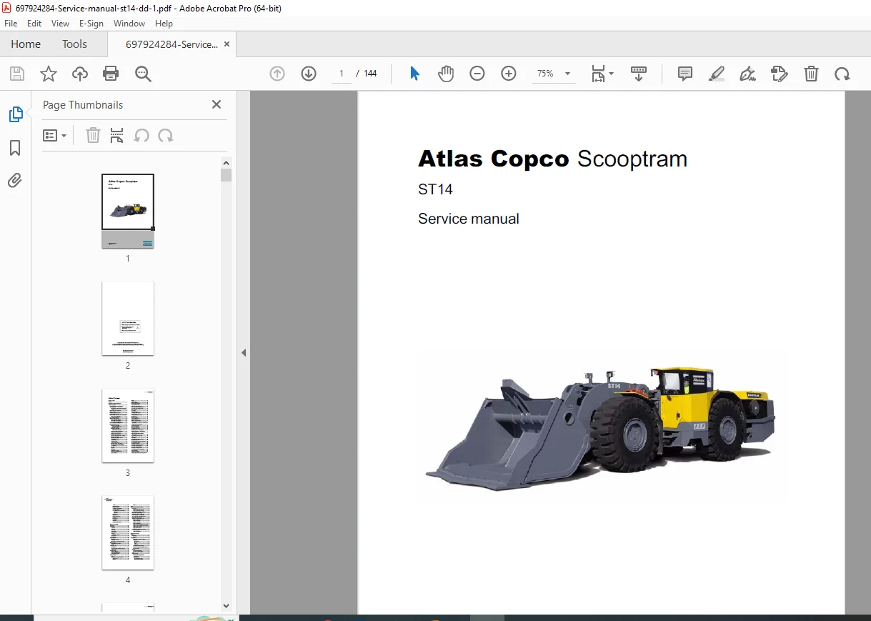
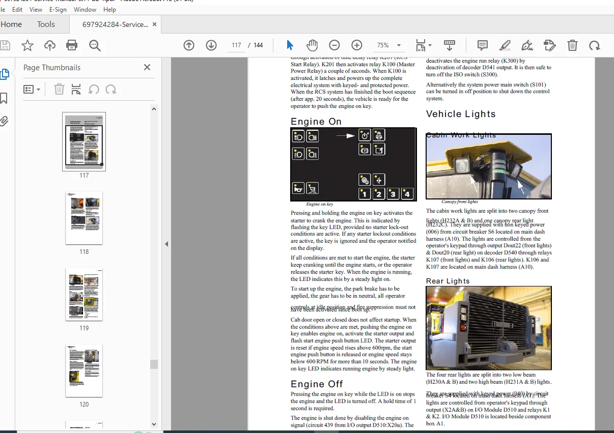
Atlas Copco Scooptram ST14 Service Manual Underground Loader Repair PDF
Original price was: $85.00.$15.95Current price is: $15.95.
Complete factory service manual for Atlas Copco Scooptram ST14 underground mining loader. This 144-page technical manual covers preventive maintenance, engine systems, transmission, hydraulics, electrical, control systems, and complete specifications. Includes Detroit Diesel Series 60 DDEC engine service, Dana T40000 transmission, hydraulic system troubleshooting, CAN bus diagnostics, and detailed component R&R procedures. Essential for technicians servicing underground LHD loaders.
Description
Atlas Copco Scooptram ST14 Service Manual Underground Loader Repair PDF DOWNLOAD
DESCRIPTION
Atlas Copco Scooptram ST14 Complete Service Manual – Underground Mining Load-Haul-Dump Loader
This comprehensive Atlas Copco ST14 service manual provides complete factory technical documentation for servicing and maintaining the ST14 Scooptram underground loader. Published in November 2007 (Part Number 9852 1825 01), this professional 144-page manual contains everything technicians need to diagnose, repair, and maintain this heavy-duty mining vehicle equipped with a 14-tonne capacity bucket.
FILE DETAILS
- Manual Type: Complete Factory Service Manual
- Model Covered: Atlas Copco Scooptram ST14 Underground Loader
- Part Number: PM nr 9852 1825 01
- Manufacturer: Atlas Copco Rock Drills AB, Sweden
- Publication Date: November 2007
- Pages: 144 pages
- File Quality: High-quality factory PDF with detailed diagrams and schematics
- File Size: 13.08 MB
- Language: English
VEHICLE SPECIFICATIONS OVERVIEW
Engine: Detroit Diesel Series 60 DDEC
- Power: 243 kW / 325 hp at 2100 rpm
- Maximum torque: 1560 Nm at 1350 rpm
Capacity & Performance:
- Scoop capacity: 14,000 kg (30,864 lbs)
- Bucket breakout force (hydraulic): 22,300 kg
- Cycle time: 15 seconds
- Operating weight (empty): 38,000 kg (83,776 lbs)
Transmission: Dana T40000 Powershift (4-speed forward/reverse) Upbox: Superior T825 (1:1 gear ratio) Axles: Dana 53R with SAHR brake system
COMPREHENSIVE MANUAL CONTENTS
This Atlas Copco ST14 loader service manual contains detailed technical information organized into 9 major chapters:
CHAPTER 1: SAFETY
Critical Safety Instructions
- Safety warnings and symbols
- Required genuine Atlas Copco parts usage
- Battery safety procedures
- Electrical safety guidelines
- Fire prevention and safety
- Proper use of safety equipment
- Emergency procedures
- Copyright and trademark information
CHAPTER 2: PREVENTIVE MAINTENANCE
Service Management System
- Complete maintenance schedules
- Service interval tracking
- Requirements for demanding mining environments
- Special tools for high-torque applications
- Pre-maintenance preparation procedures
Electric Welding Precautions
- Control system protection during welding
- Proper grounding procedures
- Disconnection requirements
Hydraulic System Cleanliness
- Contamination prevention
- Filtration standards
- Independent oil analysis programs
- Cleanliness verification procedures
Maintenance Schedules:
Break-in Period Maintenance:
- Under first shift (½ hour)
- Cooling fan drive belt inspection
- After first shift (8 hours)
- Wheel bolt and nut torque verification
- Cooling fan drive belt adjustment
- After 250 hours operation
- Boom Z-bar trunnions and pins lubrication
- Bucket trunnions and pins service
- Steering trunnions and pins inspection
- Swivel trunnions and pins lubrication
- Expander shafts service (loadframe, boom, Z-bar)
- Engine mount bolt connections
- Axle breather inspection
- Axle bolt connections torque check
- Differential and planetary gear inspection
- Driveline service (upbox-transmission, loadframe-transmission)
- Engine idle adjustments (low, high, stall speed)
- Transmission breather and bolt connections
- Upbox breather service
Every 250 Hours Operation:
- Battery maintenance and inspection
- AC cab unit service
- Cab and door inspection
- Hydraulic oil tank breather service
- Hydraulic oil filter switch check
- Brake accumulator precharge pressure verification
- Ride control accumulator precharge (if equipped)
- Tow hook accumulator precharge (if equipped)
- Brake release system check
- Engine oil and filter change
- Air filter element service
- Exhaust system inspection
- Save log and parameter files
- CAN module diagnostics
- Complete machine cleaning
- Wheel bolt/nut torque verification
- Door and hood operation check
- Steering and bucket stop adjustment
- Driveline lubrication (upbox-transmission, midship, front axle, rear axle)
- Engine fan hub bearing lubrication
Every 500 Hours Operation:
- Axle bolt connection torque check
- Driveline service (all sections)
- Engine cradle-powerframe bolt connections
- Transmission bolt connections
- AC cab unit comprehensive service
- Fuel filter replacement
- Engine cooling system hoses and pipes inspection
- Engine coolant filter replacement
- Expander shaft service (all locations)
- Load and powerframe inspection
- All trunnion and pin lubrication points
- Transmission oil and filter change
- Upbox oil filter replacement
- Hydraulic oil change and filter service
- Hydraulic oil pressure testing
- Air filter safety cartridge replacement
- Air filter indicator check
Every 1000 Hours Operation:
- Axle differential and planetary gear oil change
- Alternator inspection and service
- Engine coolant replacement
- Complete hose and coupling inspection
Every 2000 Hours Operation:
- Fuel tank cleaning and inspection
- Fuel injector service
- Fuel hose replacement
- Air intake system inspection
- Cooling fan drive belt replacement
Every 5000 Hours Operation:
- Major component overhaul inspections
- Comprehensive system evaluations
Atlas Copco Service Kits:
- Pre-assembled maintenance kits
- Kit part numbers and contents
- Application-specific service packages
CHAPTER 3: POWER UNIT
Engine Systems – Detroit Diesel Series 60 DDEC
Engine Support Systems:
- Engine removal and installation procedures
- Engine package R&R with detailed step-by-step instructions
- Lifting procedures and safety precautions
- Engine mounting and alignment
Cooling System:
- Cooling package removal and replacement
- Radiator service procedures
- Hydraulic and fuel cooler R&R
- Coolant drain and refill procedures
- Hose connection procedures
- Fan and fan shroud service
Exhaust System:
- Catalytic exhaust purifier service (if equipped)
- Silencer maintenance
- Exhaust manifold service
- Component removal and replacement
- Inspection procedures
Fuel System:
- Fuel system cleanliness requirements
- Fuel filter removal and replacement
- Fuel cooler service
- Fuel solenoid valves and lines
- Fuel tank removal and installation
- Fuel injector service (every 2000 hours)
- Fuel hose inspection and replacement
Electronic Engine Control System:
- ECM (Engine Control Module) removal
- ECM replacement procedures
- Sensor calibration
- Diagnostic procedures
- Parameter programming
CHAPTER 4: TRANSMISSION & DRIVELINE
Transmission System – Dana T40000 Powershift
- 4-speed forward and reverse operation
- Power rating: 224-313 kW / 300-420 hp
- Complete service procedures
- Oil and filter change intervals
- Bolt connection torque specifications
- Breather maintenance
Upbox – Superior T825
- 1:1 gear ratio operation
- Oil filter replacement
- Breather service
- Component inspection
Driveline Components:
- Upbox-to-transmission driveline service
- Loadframe-to-transmission-powerframe connections
- Midship driveline lubrication
- Universal joint inspection and lubrication
- Alignment procedures
Axles – Dana 53R
- Front and rear axle service
- Differential oil changes (front and rear)
- Planetary gear maintenance
- Axle breather service
- Bolt connection torque verification
- Rear axle oscillation: ±8º
- Standard differential (front), No-slip differential (rear)
CHAPTER 5: STEERING & HOIST SYSTEMS
Steering System:
- Hydraulic steering operation
- Steering cylinder service
- Trunnion and pin lubrication
- Steering linkage inspection
- Bucket stop adjustment
Boom and Bucket Systems:
- Boom Z-bar trunnions and pins
- Bucket trunnions and pins
- Expander shaft service
- Component alignment procedures
Operating Times (Performance Specifications):
- Boom raising time: 7.6 seconds
- Boom lowering time: 4 seconds
- Bucket dump time: 1.8 seconds
- Complete cycle time: 15 seconds
CHAPTER 6: HYDRAULIC SYSTEMS
Hydraulic System Overview:
- System principles and operation
- Hydraulic schematic diagrams
- Component locations
Hydraulic Pumps:
- Variable piston pump operation
- Pump removal and replacement procedures
- Flow specifications
- Installation and alignment
Hydraulic Cylinders:
- Steering Cylinders
- Removal and installation procedures
- Seal replacement
- Testing and adjustment
- Dump Cylinder
- R&R procedures
- Hydraulic connections
- Seal service
- Hoist Cylinders
- Removal procedures
- Installation and alignment
- Pressure testing
Accumulators:
- Brake accumulator precharge pressure specifications
- Ride control accumulator service (optional)
- Tow hook accumulator (optional)
- Precharge procedures
- Nitrogen charging specifications
Hydraulic Tank and Filtration:
- Tank capacity specifications
- Breather and filter maintenance
- Tank air breather service
- Hydraulic oil filter replacement
- Filter switch operation
Control Valves:
- Main Control Valve (VMC)
- Valve operation principles
- Removal and replacement
- Cartridge service procedures
- Auxiliary Valve (AUV)
- Auxiliary valve block service
- Component identification
Hydraulic Functions:
- Dump and Hoist Operations
- Boom up operation
- Boom down operation
- Bucket float function
- Ride control system (optional)
Brake System – SAHR (Spring Applied Hydraulically Released)
- System components and operation
- Pump operation (VPLS2)
- Accumulator function (ACC1)
- Auxiliary valve block operation
- Brake application procedures
- Service brake operation
- Park brake operation
- Brake cooling system
- Brake release for towing procedures
- Hand-operated hydraulic pump usage
Tow Hook with Brake Release (Optional):
- System components
- Brake release manifold
- Tow hook accumulator specifications
- Tow hook cylinder operation
- Air bleed procedures
Brake Deaeration:
- Complete deaeration procedures
- Bleeding sequence
- Pressure verification
Cooling System:
- Hydraulic oil cooler (CO2)
- Cooling pump operation (FCP)
- Brake cooling specifications
- System filtration
General Maintenance Procedures:
- Before starting service work
- Cleanliness verification
- Relieving hydraulic pressure safely
- Hose removal precautions
- Pressure setting checks and adjustments
- Dump and hoist pressure settings
- Steering pressure adjustment
- Brake pressure calibration
- Hydraulic system startup procedures
- Trial run procedures
Hydraulic Component R&R:
- Steering cylinder removal and installation
- Dump cylinder service
- Hoist cylinder procedures
- Hydraulic pump removal and replacement
- Hydraulic valve service
- Manifold replacement procedures
CHAPTER 7: ELECTRICAL SYSTEMS
System Design:
- Complete electrical architecture
- 24V DC system overview
- Power distribution design
Power Supply:
- Battery specifications (2 x 12V)
- Voltage: 24V system
- Cold cranking: 900A
- Temperature range: -40°C to 90°C
- Reserve capacity and 20h capacity ratings
Charging Circuit:
- Alternator specifications and operation
- Voltage regulation
- Charging system diagnostics
Power Circuits:
- Non-keyed Power
- Always-on circuits
- Memory retention
- Keyed Power
- Ignition-controlled circuits
- Safety interlocks
- Protected Power
- Circuit breaker protection
- Fuse specifications
- Power Grid
- Distribution architecture
- Junction box locations
- Grounding
- Grounding points
- Ground integrity verification
System Components:
Alternator:
- Specifications and operation
- Removal procedures
- Replacement and installation
- Belt tension adjustment
Starter:
- Heavy-duty starter motor specifications
- Removal procedures
- Replacement and installation
- Electrical connections
RCS (Remote Control System) Components:
- Control module specifications
- Communication protocols
- System operation
Switches and Circuit Breakers:
- ISO switch (S300) operation
- RCS On switch (S101) and Off switch (S102)
- Circuit breaker locations and ratings
- Park brake switch (S138)
- Main brake switch (B422)
- Air filter switch (B360)
- Transmission filter switch (B435)
- Hydraulic filter switch (B139)
- Bucket position sensor (B405)
- Boom position sensor (B406)
System Functions:
- Power-up vehicle procedures
- Engine start sequence
- Engine shutdown procedures
- System shutdown protocols
Vehicle Lighting:
- Cabin Work Lights – 3 x 70W
- Rear Lights – 4 x 70W (2 high beam, 2 low beam)
- Boom Lights – 4 x 70W (2 on boom, 2 for truck loading)
- Load Lights – Cargo area illumination
- Drift Light (H234) – Underground navigation
- Dome Light – Interior cabin lighting
- Status Beacon (H390) – Vehicle status indicator
Other Electrical Systems:
- Backup alarm operation
- Horn function
- CD player system
- 12V socket outlet
- Wipers and washers
- Air conditioning controls
- Door interlock safety system
- Lincoln automatic lubrication system (X5)
- Hydraulic oil fill motor
- Fuel heater system
Diagnostic Outlets:
- ECM diagnostic connector
- CAN bus diagnostic ports
- Troubleshooting interfaces
General Maintenance, Diagnosis & Calibration:
- Battery maintenance procedures
- Battery booster cable usage
- Lead-acid battery storage
- Component removal and replacement procedures
- Engine sensor service and calibration
- Diagnostic interface operation
CHAPTER 8: CONTROL SYSTEM
CAN Bus Electronic Control System:
System Modules:
- D501 Display Module – Operator interface
- D540 Decoder Module – Signal processing
- D510, D511, D512 I/O Modules – Input/output management
- D602 TCU – Transmission Control Unit
- D601 ECU – Engine Control Unit
- D520 Remote Control Machine Unit (optional)
Module Placement:
- Physical location diagrams
- Wiring harness routing
- Connector identification
Menu System:
- Access level management (operator, technician, administrator)
- Login procedures
- Menu structure navigation
- Settings adjustment procedures
Operator Functions:
- M1.7 RCS Shutdown – Automatic shutdown timing
- M2.2 Load Weigh (optional)
- Load weighing system operation
- Calibration procedures
- Settings menu
- Differential pressure monitoring
- Boom angle specifications
- Bucket position sensing
- M2.3 Ride Control (optional)
- Ride control system settings
- Accumulator management
Diagnostics Menu:
- Module status monitoring
- Fault code reading
- Real-time data display
- Parameter logging
- System health checks
- Communication status
- Event log access
Calibration Procedures:
- Load weighing calibration (step-by-step)
- Sensor calibration
- System parameter adjustment
- Reference weight procedures (9000-11000 kg)
CHAPTER 9: VEHICLE SPECIFICATIONS
Complete Technical Specifications:
Performance Data:
- Engine: Detroit Diesel Series 60 DDEC
- Power: 243 kW / 325 hp at 2100 rpm
- Maximum torque: 1560 Nm at 1350 rpm
- MSHA Part 7 ventilation rate: 7.8 m³/sec
- Ventilation particulate index: 5.2 m³/sec
Vehicle Weight:
- Empty weight: 38,000 kg (83,776 lbs)
- Front axle load: 19,100 kg (42,108 lbs)
- Rear axle load: 18,900 kg (41,668 lbs)
Scoop Capacity:
- Bucket capacity: 14,000 kg (30,864 lbs)
Breakout Forces:
- Mechanical breakout: 18,240 kg
- Hydraulic breakout: 22,300 kg
Operating Times:
- Boom raising: 7.6 seconds
- Boom lowering: 4 seconds
- Bucket dump: 1.8 seconds
- Complete cycle: 15 seconds
Speed Performance: (Level ground, bucket empty / bucket loaded)
- 1st Gear: 5.2 kph (3.2 mph) / 4.9 kph (3.0 mph)
- 2nd Gear: 10.0 kph (6.2 mph) / 9.5 kph (5.9 mph)
- 3rd Gear: 17.1 kph (10.6 mph) / 16.1 kph (10.0 mph)
- 4th Gear: 28.5 kph (17.7 mph) / 26.3 kph (16.3 mph)
Transmission:
- Dana T40000 Powershift
- 4-speed forward/reverse
- Power range: 224-313 kW / 300-420 hp
Upbox:
- Superior T825
- Gear ratio: 1:1
Axles:
- Dana 53R
- Front differential: Standard
- Rear differential: No-slip
- Rear axle oscillation: ±8º
Brakes:
- SAHR (Spring Applied Hydraulically Released)
- Fully enclosed, force cooled
- Multiple wet disc at each wheel end
- Service, parking, and emergency brake functions
Tires:
- Bridgestone 26.5 x 25, 32 Ply, L5S (tire pressure: 6.2±0.2 bar)
- Michelin 26.5R25 XMine D2 Radial (tire pressure: 6.2±0.2 bar)
Hydraulics:
- Hydraulic tank capacity specifications
- System pressure ratings
- Component capacities
Fluid Capacities:
- Fuel tank capacity
- Engine oil capacity (with filter change)
- Hydraulic system capacity
- Transmission component capacity and refill
- Upbox capacity and refill
- Front differential capacity
- Rear differential capacity
- Cooling system capacity
Electrical Specifications:
- Battery: 24V system (2 x 12V)
- Cold cranking: 900A at -18°C (0°F)
- Operating temperature: -40°C to 90°C
- Alternator specifications
Air Conditioning (Optional):
- Refrigerant type and weight specifications
- System capacity
Torque Specifications:
- Complete bolt torque charts
- Standard and high-strength hardware specifications
- Hydraulic torque tool requirements
- Special fastener requirements
- SAE Grade 8 and ISO Class 10.9 specifications
Fluid Specifications:
- Engine oil recommendations (ASTM D 975 reference)
- Hydraulic oil specifications
- Transmission fluid requirements
- Differential oil specifications
- Coolant mixture specifications
KEY FEATURES OF THIS SERVICE MANUAL
✓ Factory Original Documentation – Official Atlas Copco technical manual
✓ 144 Comprehensive Pages – Complete coverage of all systems
✓ Detailed Maintenance Schedules – Hour-based service intervals
✓ Component R&R Procedures – Step-by-step removal and installation
✓ Hydraulic Schematics – Complete system diagrams
✓ Electrical Diagrams – Wiring and circuit information
✓ CAN Bus Diagnostics – Electronic control system troubleshooting
✓ Torque Specifications – Complete fastener torque charts
✓ Fluid Specifications – Oil, coolant, and hydraulic fluid requirements
✓ Safety Procedures – Comprehensive safety guidelines
WHO NEEDS THIS MANUAL?
- Mining Equipment Technicians servicing underground loaders
- Mine Maintenance Departments maintaining LHD fleets
- Heavy Equipment Repair Shops specializing in mining equipment
- Service Centers authorized for Atlas Copco products
- Fleet Managers overseeing underground mining operations
- Technical Training Institutions teaching mining equipment service
- Equipment Operators with mechanical maintenance responsibilities
SYSTEMS COVERED
This Atlas Copco Scooptram ST14 repair manual provides complete service information for:
- Detroit Diesel Series 60 DDEC engine systems
- Dana T40000 Powershift transmission
- Superior T825 upbox
- Dana 53R axles with differentials and planetary gears
- SAHR wet disc brake system
- Variable displacement hydraulic pumps
- Electronic CAN bus control system
- Load weighing system (optional)
- Ride control system (optional)
- Remote control system (optional)
- Automatic lubrication system
- Climate control systems
This Atlas Copco ST14 service manual PDF provides the same technical information used by authorized Atlas Copco service centers worldwide. Essential for anyone maintaining, diagnosing, or repairing these heavy-duty underground mining loaders. Download immediately after purchase for instant access to complete service procedures, specifications, and troubleshooting guides for this critical mining equipment.