Atlet Truck P Series PLL PSL & PSD Service Manual – PDF DOWNLOAD
Original price was: $68.95.$30.95Current price is: $30.95.
Atlet Truck P Series PLL PSL & PSD Service Manual – PDF DOWNLOAD
Machine: PLL PSD PSL
PLE
Manual No: 119000
Description
Atlet Truck P Series PLL PSL & PSD Service Manual – PDF DOWNLOAD
DESCRIPTION:
Atlet Truck P Series PLL PSL & PSD Service Manual – PDF DOWNLOAD
Machine: PLL PSD PSL
PLE
Manual No: 119000
General :
This manual describes the service procedures for ATLET low lifters and stackers. Use the manual for quick and correct service of respective truck models. You may find contradictions in the manual compared to the models supplied due to optional designs and upgrades, and the like.
How to use the manual
Structure
- The manual is built up according to the same principles as ATLET spare parts catalogues, with the truck divided into one subsystem per section.
- Sections 1 – 3 in this manual contain more comprehensive information regarding technical data, general service instructions and tools.
- Sections 4-12 in this manual contain information limited to a specific area in the truck concerning the description of the mechanical handling of different components, e.g. Master (section 6) and Hydraulic system (section 8).
- The software is described in section 10.
- The main principle for extra accessories is to place them under the respective sections. Otherwise they are placed under section 12 “Miscellaneous”. For this reason section 12 is not always included in the Service Manual.
- For specific problems or information about procedures, look in the main index for the correct section in the manual.
Safety instructions
General
Extreme importance must be placed on precautionary measures to avoid accidents during all work on the vehicle.
A general rule is to always implement preventive measures that are adapted to the type of vehicle to be worked on. The general rules below must always be observed:
• Smoking or naked flames are strictly forbidden as there is a risk of explosion in the vicinity of batteries and while working on gas equipped vehicles.
• The battery should always be protected during grinding work.
• Local fire directives should always be followed.
• The drive wheel should always be lifted up free from the floor during service work to prevent the vehicle from moving.
• The battery plug should be pulled out before working on the electrical system. The battery plug may only be connected while trouble shooting, and when the greatest of care is exercised, (with the truck raised).
• To prevent injuries caused by crushing the battery plug should always be removed when working on and around the mast and hydraulic unit. The mast or hydraulic unit can be actuated due to an electrical fault or a mistake while working.
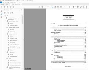
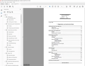
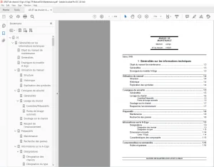
TABLE OF CONTENTS:
Atlet Truck P Series PLL PSL & PSD Service Manual – PDF DOWNLOAD
01....................................................................................  1
	1 General information and technical data..........................................  1
		Scope of Service Manual.......................................................  3
			General...................................................................  3
			Scope of the P series.....................................................  3
		How to use the manual.........................................................  4
			Structure.................................................................  4
			Symbol key................................................................  4
		Safety instructions...........................................................  5
			General...................................................................  5
			Lifting the truck.........................................................  6
			Welding on the truck......................................................  8
			Atlet AB takes care of the environment....................................  8
			Environmental impact......................................................  8
			Waste.....................................................................  8
		Preparations..................................................................  9
			Service...................................................................  9
			Trouble shooting..........................................................  9
		Data PLL, PSD................................................................. 10
			Designations.............................................................. 10
			Dimensions and weights.................................................... 14
			Component specification................................................... 16
		Recommended consumable materials.............................................. 17
			Oil and grease............................................................ 17
		Standards and abbreviations................................................... 18
			Screws.................................................................... 18
			Standard abbreviations.................................................... 20
			Colour of the truck....................................................... 22
			Colour codes, cabling..................................................... 22
			Designations.............................................................. 23
02.................................................................................... 25
	2 Special tools................................................................... 25
		Special tools PLL/PSD/PSL..................................................... 27
			Introduction.............................................................. 27
			List of tools............................................................. 27
03.................................................................................... 29
	3 Service......................................................................... 29
		Regular maintenance........................................................... 31
			Introduction.............................................................. 31
			Safety.................................................................... 31
			Recommendation............................................................ 31
			Daily inspection.......................................................... 32
			Weekly inspection (30 hours of operation)................................. 33
			First service............................................................. 33
			Main service.............................................................. 33
			Extra service inspections................................................. 34
			Check list, service inspection............................................ 35
			Code explanation.......................................................... 41
		Specific instructions......................................................... 45
			Storage of machines and motors............................................ 45
			Drive motor............................................................... 45
			Gearbox................................................................... 45
			Lift chains and forks..................................................... 47
			Hydraulic oil............................................................. 48
			Recommended replacement................................................... 48
04.................................................................................... 49
	4 Chassis......................................................................... 49
		Design and function........................................................... 51
			Scope..................................................................... 51
			Machine housing........................................................... 51
			Covers and panels......................................................... 51
			Castor wheel.............................................................. 52
		Repair instructions........................................................... 53
			Covers and panels......................................................... 53
			Castor wheel.............................................................. 54
			Battery................................................................... 56
05.................................................................................... 57
	5 Drive unit...................................................................... 57
		Design and function........................................................... 59
			Introduction.............................................................. 59
			Drive motor............................................................... 59
			Gearbox................................................................... 59
		Repair instructions........................................................... 60
			Preparations.............................................................. 60
			Drive motor............................................................... 60
			Gearbox................................................................... 61
			Drive wheel............................................................... 62
		Diagnostics and trouble shooting.............................................. 64
			Trouble shooting chart.................................................... 64
06.................................................................................... 67
	6 Mast system..................................................................... 67
		Design and function........................................................... 69
			Mast system............................................................... 69
			Fork carriage............................................................. 69
		Repair instructions........................................................... 70
			Replacing the mast........................................................ 70
			Fork carriage, general.................................................... 71
		Diagnostics and trouble shooting.............................................. 72
			Trouble shooting chart.................................................... 72
07.................................................................................... 73
	7 Steering........................................................................ 73
		Design and function........................................................... 75
			General................................................................... 75
			Steering.................................................................. 75
		Repair instructions........................................................... 76
			Cleaning.................................................................. 76
			Tiller head (-2007w27).................................................... 76
			Tiller arm head (2007w28-)................................................ 77
			Tiller arm (2007w28-)..................................................... 81
08.................................................................................... 83
	8 Hydraulic system................................................................ 83
		Design and function........................................................... 85
			General................................................................... 85
			Hose rupture valve........................................................ 85
			Electric solenoid valve................................................... 85
			Hydraulic diagram......................................................... 86
		Repair instructions........................................................... 92
			Hydraulic system.......................................................... 92
			Hydraulic oil............................................................. 93
			Motor, hydraulic unit..................................................... 94
			Hose rupture valve........................................................ 96
			Solenoid valve............................................................ 97
			Installation instruction for pipe couplings............................... 98
		Diagnostics and trouble shooting..............................................101
			Symptom and Action........................................................101
09....................................................................................103
	9 Lift cylinders..................................................................103
		Design and function...........................................................105
			Introduction..............................................................105
10....................................................................................107
	10 Electrical system..............................................................107
		Design and function...........................................................111
			General...................................................................111
		Repair instructions...........................................................114
			General...................................................................114
			Battery...................................................................115
			General handling..........................................................117
			Contactors in cold storage rooms..........................................120
			Drive and valve controller................................................121
			Insulation resistance.....................................................124
			Main Controller Unit ATC, Handling........................................125
			ATC Logic.................................................................143
			Digital I/Os..............................................................147
			Cold resistance values PLL/PSD............................................149
			Fuses.....................................................................150
		Diagnostics and trouble shooting..............................................151
			Truck Remote ACcess, TRAC.................................................151
		Appendix 1, Summary menu tree.................................................173
			INTRODUCTION..............................................................175
		Specification.................................................................175
			Technical Data............................................................175
			Block Diagram.............................................................176
			Operation Elements........................................................176
			Protection Features.......................................................177
			Thermal Considerations....................................................178
		Electrical Connections........................................................179
			Control Connectors........................................................179
			Encoder Connector (Incremental Speed Encoder).............................185
			Power Connectors..........................................................185
		Programming Setup - using Programming Console.................................186
			The ZAPI - Programming Console............................................186
			Overview on the Console functions when connected to an AC0 - MDI PRC -....189
			Configuration of Options (SET OPTIONS)....................................190
			Calibration (ADJUSTMENTS).................................................196
			Parameter setting (PARAMETER CHANGE)......................................201
			Measurement and Test Functions (TESTER)...................................204
			Saving Settings (SAVE PARAM)..............................................208
			Restoring settings (RESTORE PARAM)........................................210
			Error Messages (ALARMS)...................................................212
			Teach-In the Potentiometer Signal.........................................213
			The Setting Process.......................................................214
		Error messages................................................................216
			Monitoring Functions of the Controller....................................216
			Error-Code Table..........................................................217
		Service Instructions..........................................................222
		MDI AND MDI - PRC.............................................................223
			MDI Connection............................................................223
			Dimensions MDI IP64.......................................................224
			MDI IP64 Connection.......................................................225
			MDI-PRC...................................................................226
		GLOSSARY......................................................................228
		Adjustment Values.............................................................229
			PLL Kordel................................................................229
			PLL Sauer.................................................................235
			PSD Kordel................................................................241
			PSD Sauer.................................................................248
11....................................................................................286
	11 Brake and drive system.........................................................286
		Design and function...........................................................288
			Electric brake............................................................288
		Repair instructions...........................................................289
			Electric brake............................................................289
ATLET TRUCK P SERIES PLL PSL & PSD SERVICE MANUAL – PDF DOWNLOAD:
IMAGES PREVIEW OF THE MANUAL:
PLEASE NOTE:
- This is the same manual used by the dealers to diagnose and troubleshoot your vehicle
- You will be directed to the download page as soon as the purchase is completed. The whole payment and downloading process will take anywhere between 2-5 minutes
- Need any other service / repair / parts manual, please feel free to contact [email protected] . We still have 50,000 manuals unlisted
S.V