Audi TT 2015-2020 Complete Service Repair Workshop Manual – Download
Original price was: $33.95.$25.95Current price is: $25.95.
LANGUAGE:ENGLISH
PAGES:7721
FILE TYPE:PDF
DOWNLOADABLE:YES
Description
Audi TT 2015-2020 Complete Service Repair Workshop Manual
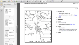
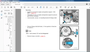
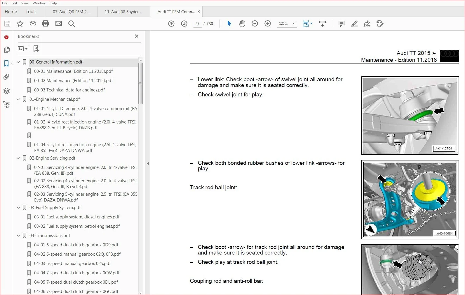
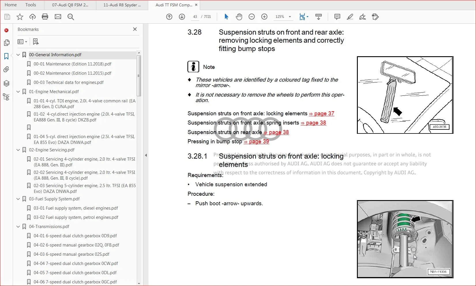
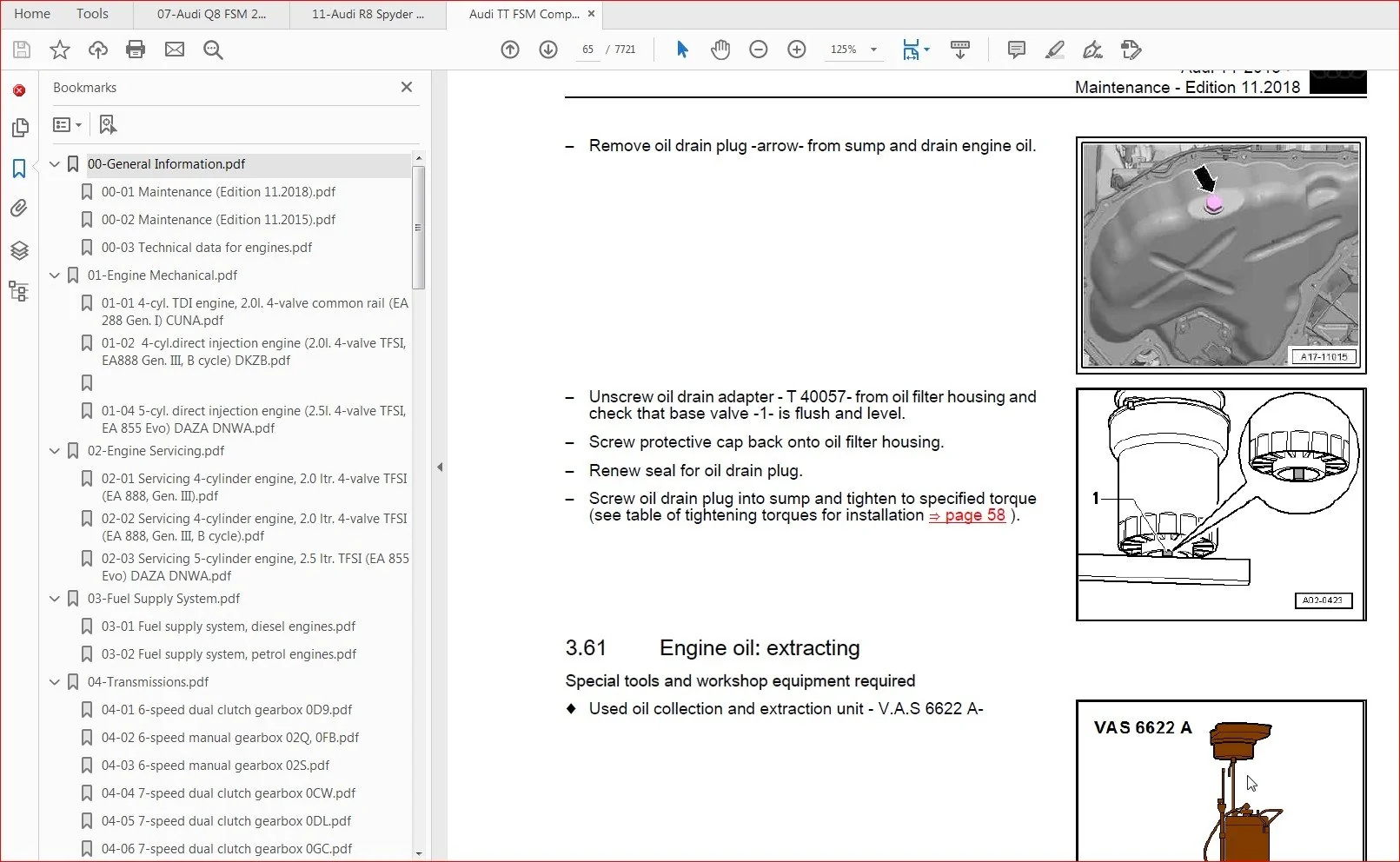
IMAGES PREVIEW OF THE MANUAL:
AUDI TT 2015-2020 COMPLETE SERVICE REPAIR WORKSHOP MANUAL – DOWNLOAD:
TABLE OF CONTENTS
1 General information 1
11 — Change history — 1
12 Engine number 1
13 Vehicle identification number 2
14 Vehicle data sticker 3
2 Preparations 4
21 Vehicle: raising 4
22 Engine cover panel: removing and installing 5
23 Noise insulation: removing and installing6
24 Window regulators: activating automatic open/close function 6
25 Vehicle diagnostic tester: connecting 7
3 Maintenance 9
31 Diesel particulate filter: reading out ash deposit volume12
32 Event memory: reading out 13
33 Service interval display: resetting service event 13
34 Diagnostic work: performing 13
35 Transport mode: deactivating 14
36 Transport mode: checking activation and activating if necessary14
37 Battery: reading out status15
38 Connecting vehicle diagnostic tester and sending diagnostic log15
39 Battery: checking electrolyte level16
310 Battery: connecting stationary battery charging unit (min 30A, charging voltage max 148 V
on IV characteristic curve)19
311 Battery: determining and recording state of charge (SOC) 20
312 Mirror hanger indicating defective battery: renewing battery on affected vehicles23
313 Data sheet for Radio Equipment Directive: printing and placing in glove compartment 23
314 Connectivity box: checking emergency battery 23
315 Brake fluid: changing 24
316 Brake fluid (vehicles older than 12 months): changing 29
317 Brake fluid: checking fluid level 29
318 Brake system: checking condition of brake hoses, and checking that caps are fitted on bleeder
screws 29
319 Brake pads: checking thickness 30
320 Tyres: checking condition and wear pattern, and checking and recording tread depth 31
321 Brake discs: checking for surface rust and operating brakes to clean if necessary 32
322 Parking brake: releasing 33
323 Tyres: checking tyre pressures and adjusting if necessary 33
324 Tyres (except spare wheel): checking tyre pressures and adjusting to 35 bar if necessary
35
325 Tyre Pressure Loss Indicator: storing changed tyre pressures 35
326 Tyre repair kit: checking that set is complete, and checking and recording expiry date35
327 Wheel bolts: tightening to specified torque36
328 Suspension struts on front and rear axle: removing locking elements and correctly fitting
bump stops37
329 Axles (front and rear): checking components for play, secure attachment and damage, and
checking protective boots40
330 Engine, gearbox, final drive and steering: checking for leaks and damage 43
331 Vehicle (from below): checking for damage 44
332 Underbody: checking trim, wheel housing liners, side members and pipes/wiring for damage,
and checking that they are properly secured 44
333 Rear spoiler hinges: lubricating 44
334 Windscreen/rear window washer system: checking spray pattern and adjusting if
necessary45
335 Wiper blades: checking for damage 46
336 Headlight washer system: checking operation 46
Audi TT 2015 ➤
Maintenance – Edition 112018
Contents i
337 Headlights: checking for correct adjustment 46
338 Headlights and reversing lights, side lights, number plate lights, turn signals, hazard warning
lights: checking operation47
339 Luggage compartment lighting: checking operation 48
340 Luggage compartment: removing protective film and felt pieces49
341 Glove box light, interior lighting and reading light: checking operation 49
342 Horn: checking operation49
343 Passenger airbag: checking key switch on/off and setting to “on”50
344 Owner’s literature: checking that all documents are present 50
345 Service wallet: affixing vehicle data sticker 50
346 Service Schedule: entering Delivery Inspection 50
347 Seat belts: checking fixing device for latch plate, and checking locking action of automatic
belt retractor 51
348 Vehicle interior: removing protective covers for seats and carpet51
349 Vehicle interior: checking that it is clean and cleaning if necessary 51
350 Vehicle interior: removing any objects other than those protecting interior surfaces 52
351 Vehicle interior and exterior: checking for and documenting any damage52
352 Instrument cluster: checking warning lamps 52
353 Warning triangle: checking availability 52
354 First-aid kit: checking and recording expiry date52
355 Vehicle key(s): checking operation and recording number of keys given to customer 53
356 Vehicle key: removing from ignition lock53
357 Vehicle key(s), wheel covers and owner’s literature: checking availability and recording
number present 53
358 Sun visors: checking that they are folded up and folding up if necessary53
359 Luggage compartment cover and sun blind: checking that they are rolled up and rolling up if
necessary54
360 Engine oil: draining54
361 Engine oil: extracting 59
362 Engine oil: renewing oil filter 60
363 Engine oil: filling up 63
364 Engine oil: checking oil level and correcting if necessary64
365 Spark plugs: renewing 65
366 Coolant level: checking (coolant level must reach at least top marking on coolant expansion
tank) 70
367 Air cleaner: renewing filter element and cleaning housing73
368 Dust and pollen filter: renewing 76
369 Fuel filter: renewing 78
370 Fuel filter: draining79
371 Fuel tank: adding fuel additive 80
372 Door hinges with separate door arrester: cleaning and lubricating 81
373 Vehicle doors: removing edge protection81
374 Vehicle exterior: checking unprotected areas for dirt, and cleaning if necessary82
375 Vehicle exterior: removing protective film82
376 Vehicle cover: checking position and correcting if necessary 82
377 Vehicle cover: removing according to manufacturer’s instructions 82
378 Paintwork, trims, side windows and wiper blades: checking cleanliness82
379 Body: checking vehicle paintwork for damage and corrosion from below and with bonnet, rear
lid and doors open82
380 Vehicles parked outdoors: locking82
381 Road test82
382 Stock vehicles: observing measures specified in Maintenance table for stock vehicles (see
“Before handing vehicle over to customer”) 83
383 Accessories: installing 83
384 Checklist “Documentation of cleaning and care routine”: checking that list is present 84
385 “Stock vehicle maintenance” checklist: signing and placing in vehicle wallet 84
386 Cleaning and care: checking that required measures have been carried out on time 84
Audi TT 2015 ➤
Maintenance – Edition 112018
ii Contents
387 Stock vehicle care management: deciding and recording date of next check 84
388 Display instruments: setting time and date84
389 Manual gearbox/automatic gearbox: selecting 1st gear/park 85
390 Dual clutch gearbox (S tronic): changing gear oil and renewing oil filter85
391 Four-wheel drive coupling: changing oil 85
392 Interior mirror: calibrating compass 85
393 Poly V-belt for ancillaries: renewing 85
394 Poly V-belts for ancillaries and all pulleys: renewing 85
395 Instrument cluster: resetting driver information system 85
396 Toothed belt for camshaft drive: renewing86
397 Toothed belt for camshaft drive and tensioning roller: renewing86
4 Exhaust emissions test 87
41 Petrol engines: performing exhaust emissions test 87
42 Diesel engines: performing exhaust emissions test 94
Audi TT 2015 ➤
Maintenance – Edition 112018
Contents
00 – Technical data 1
1 Identification 1
11 Engine number/engine data 1
2 Safety precautions2
21 Safety precautions when working on the fuel supply system 2
22 Safety precautions when using testers and measuring instruments during a road test 3
23 Safety precautions when working on the cooling system4
24 Safety precautions when working on vehicles with start/stop system 4
25 Safety precautions when working on the exhaust system4
3 Repair instructions6
31 Rules for cleanliness 6
32 General notes 6
33 General repair instructions7
34 Performing adaptions after renewing a component 8
35 Bolts/nuts8
36 Identification plates8
37 Use of impact wrenches 9
38 Foreign particles in engine9
39 Contact corrosion9
310 Routing and attachment of pipes, hoses and wiring 10
311 Installing radiators and condensers 10
10 – Removing and installing engine11
1 Removing and installing engine 11
11 Removing engine11
12 Separating engine and gearbox 23
13 Securing engine to engine and gearbox support24
14 Installing engine 26
2 Assembly mountings 30
21 Exploded view – assembly mountings 30
22 Supporting engine in installation position32
23 Removing and installing engine mountings 33
24 Removing and installing gearbox mounting 34
25 Removing and installing pendulum support 36
26 Checking adjustment of assembly mountings (engine/gearbox mountings) 37
27 Adjusting assembly mountings 37
3 Engine cover panel40
31 Removing and installing engine cover panel 40
13 – Crankshaft group41
1 Cylinder block (pulley end)41
11 Exploded view – cylinder block (pulley end) 41
12 Exploded view – sealing flange (pulley end) 43
13 Removing and installing poly V-belt 44
14 Removing and installing tensioner for poly V-belt46
15 Removing and installing vibration damper46
16 Removing and installing bracket for ancillaries 47
17 Removing and installing engine support48
18 Removing and installing sealing flange (pulley end) 49
2 Cylinder block (gearbox end) 52
21 Exploded view – cylinder block (gearbox end) 52
22 Removing and installing flywheel53
Audi TT 2015 ➤ , Audi TT Coupé 2015 ➤ , Audi TT Roadster 2015 ➤
4-cylinder TDI engine, 20 ltr 4-valve common rail (EA 288 Gen I) – Edition 052019
Contents i
23 Removing and installing sealing flange (gearbox end) 54
3 Crankshaft68
31 Crankshaft dimensions 68
32 Measuring axial clearance of crankshaft68
4 Pistons and conrods 69
41 Exploded view – pistons and conrods 69
42 Removing and installing pistons 71
43 Measuring piston projection at TDC 73
44 Checking pistons and cylinder bores 74
45 Checking radial clearance of conrod bearings 75
15 – Cylinder head, valve gear 77
1 Toothed belt drive77
11 Exploded view – toothed belt cover 77
12 Exploded view – toothed belt 78
13 Removing and installing toothed belt cover 79
14 Detaching toothed belt from camshaft 83
15 Removing and installing toothed belt 93
2 Cylinder head 104
21 Exploded view – cylinder head cover 104
22 Exploded view – cylinder head 106
23 Removing and installing cylinder head cover 108
24 Removing and installing seals for injectors 110
25 Removing and installing camshaft housing 111
26 Removing and installing cylinder head 115
27 Checking compression 124
3 Valve gear126
31 Exploded view – valve gear 126
32 Removing and installing camshaft oil seal130
33 Removing and installing camshaft control valve 1 N205131
34 Removing and installing camshaft adjuster 132
35 Removing and installing control valve from camshaft control valve 1 N205 134
36 Removing and installing valve stem oil seals 137
4 Inlet and exhaust valves 145
41 Checking valve guides 145
42 Checking valves 146
43 Valve dimensions146
17 – Lubrication 147
1 Sump/oil pump 147
11 Exploded view – sump/oil pump 147
12 Removing and installing oil level and oil temperature sender G266 149
13 Removing and installing sump 150
14 Removing and installing oil pump154
15 Engine oil154
2 Engine oil cooler 155
3 Oil filter/oil pressure switches 156
31 Exploded view – oil filter housing/oil pressure switch 156
32 Removing and installing oil filter housing157
33 Removing and installing oil pressure switch F22160
34 Removing and installing oil pressure switch for reduced oil pressure F378 161
35 Removing and installing valve for oil pressure control N428 162
36 Checking oil pressure 163
19 – Cooling 165
Audi TT 2015 ➤ , Audi TT Coupé 2015 ➤ , Audi TT Roadster 2015 ➤
4-cylinder TDI engine, 20 ltr 4-valve common rail (EA 288 Gen I) – Edition 052019
ii Contents
1 Cooling system/coolant 165
11 Connection diagram – coolant hoses 165
12 Checking cooling system for leaks166
13 Draining and filling cooling system without electric vacuum pump VAS 6096/2169
14 Filling cooling system with electric vacuum pump VAS 6096/2 176
15 Checking electric vacuum pump VAS 6096/2 182
16 Flushing cooling system 182
17 Flushing cooling system – quick reference guide203
2 Coolant pump/thermostat assembly 205
21 Exploded view – coolant pump/thermostat205
22 Exploded view – electric coolant pump 207
23 Exploded view – coolant temperature senders 209
24 Removing and installing coolant pump 210
25 Removing and installing thermostat 210
26 Removing and installing coolant valve for cylinder head N489 212
27 Checking thermostat 213
28 Removing and installing coolant temperature sender G62 213
29 Removing and installing electric coolant pump 214
3 Coolant pipes 218
31 Exploded view – coolant pipes 218
32 Removing and installing coolant pipes 219
4 Radiators/radiator fans 233
41 Exploded view – radiators/radiator fans 233
42 Removing and installing radiator235
43 Removing and installing radiator cowl 239
44 Removing and installing radiator fan V7240
21 – Turbocharging/supercharging 241
1 Turbocharger 241
11 Exploded view – turbocharger 241
12 Removing and installing turbocharger 243
13 Renewing vacuum unit for turbocharger249
2 Charge air system254
21 Exploded view – charge air system254
22 Exploded view – hose connections for charge air system256
23 Removing and installing charge pressure sender G31 256
24 Removing and installing charge air temperature sender257
25 Checking charge air system for leaks 257
23 – Mixture preparation – injection 263
1 Injection system 263
11 Overview of fitting locations – injection system 263
12 Overview – fuel system 269
13 Filling and bleeding fuel system 270
14 Checking fuel system for leaks 271
2 Vacuum system 272
21 Connection diagram – vacuum system 272
22 Checking vacuum system273
3 Air cleaner274
31 Exploded view – air cleaner housing 274
32 Removing and installing air cleaner housing 275
4 Intake manifold 277
41 Exploded view – intake manifold 277
42 Removing and installing throttle valve module J338 279
Audi TT 2015 ➤ , Audi TT Coupé 2015 ➤ , Audi TT Roadster 2015 ➤
4-cylinder TDI engine, 20 ltr 4-valve common rail (EA 288 Gen I) – Edition 052019
Contents iii
43 Removing and installing intake manifold281
5 Injectors/high-pressure reservoir (rail) 285
51 Exploded view – injectors285
52 Exploded view – high-pressure reservoir (rail) 288
53 Checking injectors289
54 Performing adaption of correction values for injectors 289
55 Checking for injectors sticking open 289
56 Checking return flow rate of injectors with engine running291
57 Checking return flow rate of injectors at starter cranking speed295
58 Removing and installing injectors297
59 Removing and installing high-pressure pipes 301
510 Removing and installing high-pressure reservoir (rail) 304
6 High-pressure pump 306
61 Exploded view – high-pressure pump 306
62 Removing and installing high-pressure pump 307
7 Senders and sensors 310
71 Removing and installing fuel temperature sender G81 310
72 Removing and installing air mass meter G70 310
73 Checking fuel pressure regulating valve N276 312
74 Removing and installing fuel pressure regulating valve N276 313
75 Removing and installing fuel pressure sender G247 317
8 Lambda probe 321
81 Exploded view – Lambda probe 321
82 Removing and installing Lambda probe 322
9 Engine control unit325
91 Removing and installing engine/motor control unit J623325
26 – Exhaust system330
1 Exhaust pipes/silencer 330
11 Exploded view – silencer 330
12 Removing and installing front exhaust pipe 332
13 Removing and installing rear silencer 333
14 Stress-free alignment of exhaust system334
15 Checking exhaust system for leaks 334
2 Emission control system 336
21 Exploded view – emission control system336
22 Removing and installing emission control module338
23 Removing and installing pressure differential sender G505 345
24 Removing and installing exhaust gas pressure sensor 1 G450346
25 Removing and installing exhaust flap control unit J883347
3 Exhaust gas temperature control349
31 Exploded view – exhaust gas temperature control349
32 Removing and installing exhaust gas temperature sender 350
4 Exhaust gas recirculation355
41 Exploded view – exhaust gas recirculation system355
42 Removing and installing exhaust gas recirculation control motor V338357
43 Removing and installing exhaust gas recirculation control motor 2 V339358
44 Removing and installing exhaust gas recirculation cooler360
45 Checking exhaust gas recirculation cooler for leaks 364
28 – Glow plug system368
1 Glow plug system368
11 Exploded view – glow plug system368
12 Removing and installing glow plug369
Audi TT 2015 ➤ , Audi TT Coupé 2015 ➤ , Audi TT Roadster 2015 ➤
4-cylinder TDI engine, 20 ltr 4-valve common rail (EA 288 Gen I) – Edition 052019
iv Contents
13 Removing and installing automatic glow period control unit J179372
14 Removing and installing Hall sender G40372
15 Removing and installing engine speed sender G28 373
00 – Technical data 1
1 Identification 1
11 Engine number/engine data 1
12 Engine versions 1
2 Safety precautions5
21 Safety precautions when working on the fuel supply system 5
22 Safety precautions when working on vehicles with start/stop system 5
23 Safety precautions when using testers and measuring instruments during a road test 6
24 Safety precautions when working on the cooling system6
25 Safety precautions when working on the exhaust system6
26 Safety precautions when working on the ignition system7
3 Repair instructions8
31 Identification plates8
32 Use of impact wrenches 8
33 Nuts, bolts9
34 Rules for cleanliness 9
35 Foreign particles in engine9
36 Contact corrosion10
37 Routing and attachment of pipes, hoses and wiring 10
38 Installing radiators and condensers 10
39 Checking vacuum system10
10 – Removing and installing engine12
1 Removing and installing engine 12
11 Removing engine12
12 Separating engine and gearbox 12
13 Securing engine to engine and gearbox support12
14 Installing engine 13
2 Assembly mountings 14
3 Engine cover panel15
31 Removing and installing engine cover panel 15
13 – Crankshaft group16
1 Cylinder block (pulley end)16
11 Exploded view – cylinder block (pulley end) 16
12 Removing and installing poly V-belt 18
13 Removing and installing poly V-belt tensioner 19
14 Removing and installing vibration damper19
15 Removing and installing bracket for ancillaries 26
16 Removing and installing engine support27
2 Cylinder block (gearbox end) 28
21 Exploded view – cylinder block (gearbox end) 28
22 Exploded view – drive plate 29
23 Removing and installing flywheel30
24 Removing and installing drive plate 31
25 Removing and installing sealing flange (gearbox end) 33
3 Crankshaft37
31 Exploded view – crankshaft 37
32 Crankshaft dimensions 39
33 Allocation of main bearing shells39
34 Renewing needle bearing in crankshaft 40
35 Measuring axial clearance of crankshaft42
Audi A1 2011 ➤ , Audi A3 2013 ➤ , Audi A3 Limousine China 2014 ➤ , Audi
Servicing 4-cylinder engine, 20 ltr 4-valve TFSI (EA 888, Gen III) – Edition 122019
Contents i
36 Measuring radial clearance of crankshaft43
37 Removing and installing sender wheel 44
4 Balance shaft 45
41 Exploded view – balance shaft 45
42 Removing and installing balance shaft 46
43 Renewing oil seal for balance shaft (inlet side) 50
5 Pistons and conrods 52
51 Exploded view – pistons and conrods 52
52 Removing and installing pistons 55
53 Removing and installing oil spray jets 56
54 Checking pistons and cylinder bores 58
55 Separating parts of new conrod 59
56 Checking radial clearance of conrod bearings 60
15 – Cylinder head, valve gear 61
1 Timing chain cover61
11 Exploded view – timing chain cover 61
12 Removing and installing timing chain cover 65
13 Renewing oil seal for vibration damper 70
2 Chain drive73
21 Exploded view – camshaft timing chains73
22 Exploded view – drive chain for balance shaft 77
23 Removing and installing bearing saddle 79
24 Removing and installing camshaft timing chain 90
25 Removing and installing drive chain for balance shaft 118
26 Checking timing chain 119
27 Checking valve timing 121
3 Cylinder head 126
31 Exploded view – cylinder head 126
32 Removing and installing cylinder head 129
33 Checking compression 133
4 Valve gear135
41 Exploded view – valve gear 135
42 Removing and installing camshaft142
43 Installing ball for slider 182
44 Removing and installing actuators for camshaft adjustment 183
45 Removing and installing camshaft control valve 1 N205184
46 Removing and installing valve stem oil seals 184
5 Inlet and exhaust valves 195
51 Checking valve guides 195
52 Checking valves 195
53 Valve dimensions196
17 – Lubrication 197
1 Sump/oil pump 197
11 Exploded view – sump/oil pump 197
12 Engine oil200
13 Removing and installing sump (bottom section) 200
14 Removing and installing oil pump202
15 Removing and installing sump (top section) 204
16 Removing and installing oil level and oil temperature sender G266 207
2 Engine oil cooler 209
21 Exploded view – engine oil cooler209
22 Removing and installing engine oil cooler209
23 Removing and installing mechanical switching valve 210
Audi A1 2011 ➤ , Audi A3 2013 ➤ , Audi A3 Limousine China 2014 ➤ , Audi
Servicing 4-cylinder engine, 20 ltr 4-valve TFSI (EA 888, Gen III) – Edition 122019
ii Contents
3 Crankcase breather 211
31 Exploded view – crankcase breather system 211
32 Removing and installing oil separator 212
4 Oil filter/oil pressure switches 214
41 Exploded view – oil filter 214
42 Exploded view – oil pressure switches/oil pressure control 215
43 Removing and installing oil pressure switch F22216
44 Removing and installing oil pressure switch for reduced oil pressure F378 216
45 Removing and installing stage 3 oil pressure switch F447 217
46 Removing and installing valve for oil pressure control N428 218
47 Removing and installing piston cooling jet control valve N522 219
48 Checking oil pressure 219
19 – Cooling 223
1 Cooling system/coolant 223
11 Connection diagram – coolant hoses 223
12 Checking cooling system for leaks223
13 Draining and filling cooling system226
2 Coolant pump/thermostat assembly 227
21 Exploded view – coolant pump/thermostat227
22 Exploded view – electric coolant pump 229
23 Exploded view – coolant valves 229
24 Exploded view – coolant temperature senders 229
25 Removing and installing electric coolant pump 230
26 Removing and installing coolant pump 230
27 Removing and installing toothed belt for coolant pump 231
28 Removing and installing actuator for engine temperature regulation N493 232
29 Removing and installing coolant temperature sender G62 234
210 Removing and installing radiator outlet coolant temperature sender G83 235
211 Removing and installing coolant valves 235
3 Coolant pipes 236
4 Radiator/radiator fans 237
21 – Turbocharging/supercharging 238
1 Turbocharger 238
2 Charge air system239
21 Exploded view – charge air system239
22 Exploded view – hose connections for charge air system239
23 Removing and installing charge air cooler239
24 Removing and installing charge pressure sender G31 239
25 Checking charge air system for leaks 239
24 – Mixture preparation – injection 241
1 Injection system 241
2 Air cleaner242
3 Intake manifold 243
31 Exploded view – intake manifold 243
32 Removing and installing intake manifold244
33 Removing and installing throttle valve module GX3 247
34 Cleaning throttle valve module 248
35 Checking intake manifold change-over function 249
4 Injectors 251
41 Exploded view – fuel rail with injectors 251
42 Removing and installing fuel rail 253
Audi A1 2011 ➤ , Audi A3 2013 ➤ , Audi A3 Limousine China 2014 ➤ , Audi
Servicing 4-cylinder engine, 20 ltr 4-valve TFSI (EA 888, Gen III) – Edition 122019
Contents iii
43 Removing and installing injectors254
44 Cleaning injectors261
5 Senders and sensors 263
51 Exploded view – actuator for structure-borne sound and control unit for structure-borne
sound 263
52 Removing and installing actuator for structure-borne sound R214 263
53 Removing and installing control unit for structure-borne sound J869 263
54 Removing and installing intake air temperature sender G42 / intake manifold pressure sender
G71 263
55 Removing and installing fuel pressure sender G247 264
56 Checking fuel pressure sender G247 265
57 Removing and installing fuel pressure sender for low pressure G410 267
58 Removing and installing pressure differential sender for particulate filter G1037268
6 High-pressure pump 269
61 Exploded view – high-pressure pump 269
62 Removing and installing high-pressure pump 272
63 Removing and installing high-pressure pipe 275
7 Lambda probe 278
71 Exploded view – Lambda probe 278
72 Removing and installing Lambda probe 280
8 Engine control unit281
26 – Exhaust system282
1 Exhaust pipes/silencers 282
11 Exploded view – silencers282
12 Separating exhaust pipes/silencers 282
13 Removing and installing front silencers 282
14 Stress-free alignment of exhaust system282
15 Checking exhaust system for leaks 282
2 Emission control system 283
3 Exhaust gas temperature control284
31 Exploded view – exhaust gas temperature control284
32 Removing and installing parts of exhaust gas temperature control 285
4 Secondary air system 290
41 Exploded view – secondary air system 290
42 Removing and installing secondary air pump motor V101 292
43 Removing and installing secondary air inlet valve N112293
44 Removing and installing sender 1 for secondary air pressure G609 293
28 – Ignition system 295
1 Ignition system 295
11 Exploded view – ignition system 295
12 Removing and installing ignition coils 296
13 Removing and installing knock sensor 1 G61 298
14 Removing and installing Hall senders 299
15 Removing and installing engine speed sender G28 301
00 – Technical data 1
1 Safety precautions1
11 Safety precautions when working on the fuel system 1
12 Safety precautions when working on vehicles with start/stop system 2
13 Safety precautions when using testers and measuring instruments during a road test 3
14 Safety precautions when working on the SCR system 3
2 Repair instructions5
21 Rules for cleanliness 5
22 Test conditions 5
23 Contact corrosion5
20 – Fuel supply system 7
1 Fuel tank 7
11 Exploded view – fuel tank7
12 Routing and attachment of earth connection for electrostatic discharge9
13 Draining fuel tank10
14 Removing and installing fuel tank12
15 Deactivating misfuelling prevention device 23
2 Fuel delivery unit/fuel gauge senders 24
21 Exploded view – fuel delivery unit/fuel gauge sender, vehicles with front-wheel drive 24
22 Exploded view – fuel delivery unit/fuel gauge senders, vehicles with four-wheel drive 26
23 Removing and installing fuel delivery unit/fuel gauge sender 27
24 Removing and installing fuel gauge sender G 32
25 Removing and installing fuel gauge sender 2 G169 33
26 Checking suction-jet pump37
27 Removing and installing suction-jet pump37
3 Plug-in connectors44
31 Disconnecting plug-in connectors44
4 Fuel filter 48
41 Exploded view – fuel filter48
42 Removing and installing fuel filter49
5 Fuel pump51
51 Checking fuel system pressurisation pump G6 51
52 Removing and installing fuel pump control unit J538 57
6 Accelerator mechanism 59
61 Exploded view – accelerator pedal module59
62 Removing and installing accelerator pedal module with accelerator position sender G79 /
G185 60
Audi TT 2015 ➤
Fuel supply system, diesel engines – Edition 122018
Contents
00 – Technical data 1
1 Safety precautions1
11 General safety precautions 1
12 Safety precautions when working on vehicles with start/stop system 1
13 Safety precautions when using testers and measuring instruments during a road test 2
14 Safety precautions when tow-starting and towing2
2 Identification 3
21 Gearbox identification 3
22 Bevel box identification 4
3 Repair instructions5
31 General notes 5
32 Safety functions of gearbox control unit 5
33 Rules for cleanliness 6
34 General repair instructions6
35 Contact corrosion8
4 Technical data 9
41 Capacities9
30 – Clutch 10
1 Clutch 10
11 Exploded view – dual clutch 10
12 Removing dual clutch 10
13 Installing dual clutch 13
34 – Controls, housing22
1 Selector mechanism 22
11 Exploded view – selector lever handle 22
12 Exploded view – selector mechanism 27
13 Manual release from position P 29
14 Removing and installing selector lever handle 33
15 Bringing interlock button in handle into installation position 35
16 Removing and installing selector mechanism 37
17 Checking selector mechanism 39
18 Checking and adjusting selector lever cable 42
19 Renewing selector shaft oil seal 43
2 Removing and installing gearbox47
21 Tightening torques for gearbox 47
22 Removing gearbox48
23 Installing gearbox67
3 Transporting gearbox 71
4 Securing to engine and gearbox support73
5 Assembly mountings 75
51 Exploded view – assembly mountings 75
6 Bevel box76
61 Exploded view – bevel box76
62 Removing bevel box 76
63 Installing bevel box81
64 Tightening torques for bevel box82
7 Mechatronic unit 83
71 Exploded view – mechatronic unit83
72 Removing and installing oil pan 85
Audi A1 Sportback 2018 ➤ , Audi A3 2013 ➤ , Audi Q2 2016 ➤ , Audi Q3 20
6-speed dual clutch gearbox 0D9 – Edition 062019
Contents i
73 Removing and installing mechatronic unit87
74 Renewing securing clip on vehicle connector 90
75 Removing and installing gear oil pump 91
8 Gear oil circuit 94
81 Overview – gear oil circuit94
82 Removing and installing gear oil cooler 94
83 Removing and installing gear oil filter 97
9 Gear oil 99
91 Tools for changing gear oil99
92 Checking gear oil level 100
93 Draining and filling gear oil103
35 – Gears, shafts 106
1 Dismantling and assembling gears and shafts 106
39 – Final drive – differential 107
1 Gearbox control system 107
11 Overview of fitting locations – gearbox control system 107
2 Oil seals 108
21 Overview of fitting locations – oil seals 108
22 Renewing oil seal (left-side) 109
23 Renewing oil seal (right-side) 110
3 Differential113
31 Exploded view – differential 113
32 Removing and installing flange shaft (left-side) 114
33 Removing and installing flange shaft (right-side)115
4 Components of bevel box120
41 Exploded view – components of bevel box120
42 Renewing oil seals for bevel box121
5 Gear oil 135
51 Tools for changing gear oil135
52 Checking gear oil level 136
53 Draining and filling gear oil138
00 – Technical data 1
1 Identification 1
11 Identification of final drive1
2 Technical data 2
21 Capacities2
22 Allocation of gearbox to engine 2
3 Transmission layout 7
31 Transmission layout – four-wheel drive 7
4 Repair instructions9
41 General repair instructions9
42 Contact corrosion11
5 Safety precautions12
51 General safety precautions 12
52 Safety precautions when using testers and measuring instruments during a road test 12
53 Safety precautions when working on vehicles with start/stop system 12
6 Electrical components 14
61 Overview of fitting locations – electrical components 14
39 – Final drive – rear differential 15
1 Propshaft15
11 Exploded view – propshaft15
12 Removing and installing propshaft17
13 Removing and installing flexible coupling (rear) 31
2 Final drive36
21 Exploded view – final drive36
22 Removing and installing final drive37
3 Assembly mountings 47
31 Exploded view – assembly mountings 47
32 Removing and installing bonded rubber bushes48
4 Oil seals 52
41 Overview of fitting locations – oil seals 52
42 Renewing oil seal (left-side) 53
43 Renewing oil seal (right-side) 55
44 Renewing input shaft oil seal 57
5 Gear oil 64
51 Overview of fitting locations – drain and inspection plugs64
52 Checking gear oil level 64
6 Four-wheel drive coupling67
61 Exploded view – four-wheel drive coupling67
62 Function test 68
63 Removing and installing four-wheel drive coupling 68
64 Removing and installing all-wheel drive coupling pump 73
65 Removing and installing control unit 76
66 Checking oil level76
67 Draining and filling fluid for four-wheel drive coupling 78
Audi A3 2013 ➤ , Audi A3 Cabriolet 2015 ➤ , Audi A3 Sportback 2013 ➤ , A
Rear final drive 0CQ, 0CR, 0BR – Edition 122019
Contents
00 – Technical data 1
1 Identification 1
11 PR number and type of brake system 1
2 Safety precautions2
21 Safety precautions when working on vehicles with start/stop system 2
22 Safety precautions when using testers and measuring instruments during a road test 2
3 Technical data 3
31 Technical data for brakes3
4 Brake test6
41 General notes 6
42 Testing vehicles with front-wheel drive 6
43 Testing vehicles with four-wheel drive 6
44 Testing parking brake 6
5 Checking ceramic brake discs 8
51 Visible features of ceramic brake discs 8
52 Superficial cracks in cooling channel lands 9
53 Cracks in area of bolted connection on ceramic brake discs 9
54 Edge fractures 10
55 Chipping on ceramic brake discs10
56 Cracks extending into cooling channels 11
57 Assessing degree of wear on ceramic brake discs 11
58 Wear assessment of ceramic brake disc with tester VAS 681313
45 – Anti-lock brake system 21
1 General notes 21
11 Notes for repair work on the ABS21
2 Overview of fitting locations 22
21 Overview of fitting locations – ABS/ESP 22
3 Control unit and hydraulic unit 24
31 Exploded view – control unit and hydraulic unit 24
32 Removing and installing ABS control unit J104 / ABS hydraulic unit N5527
33 Separating control unit from hydraulic unit38
34 Attaching control unit to hydraulic unit 41
4 Sensors 44
41 Exploded view – front wheel speed sensor44
42 Exploded view – rear wheel speed sensor45
43 Removing and installing brake light switch46
44 Removing and installing front wheel speed sensor G45 / G47 48
45 Removing and installing rear wheel speed sensor G44 / G46 49
46 Checking ABS speed sensor ring50
46 – Brakes – mechanism 52
1 Front brakes (1LJ/1ZD etc) 52
11 Exploded view – front brakes (1JL/1ZD etc) 52
12 Removing and installing brake pads (1JL/1ZD etc) 56
13 Removing and installing brake caliper (1JL/1ZD etc) 61
14 Renewing brake caliper (1JL/1ZD etc) 64
15 Removing and installing brake carrier (1JL/1ZD etc) 70
16 Removing and installing brake disc (1JL/1ZD etc) 72
17 Removing and installing splash plate (1JL/1ZD etc) 74
2 Front brakes (1LK/1LH) – TTS 76
21 Exploded view – brakes (1LK/1LH), TTS76
Audi TT 2015 ➤
Brake system – Edition 032019
Contents i
22 Retaining plates for brake pads 78
23 Removing and installing brake pads (1LK/1LH) – TTS 79
24 Removing and installing brake caliper (1LK/1LH) – TTS84
25 Renewing brake caliper (1LK/1LH) – TTS86
26 Removing and installing brake disc (1LK/1LH) – TTS 93
27 Removing and installing splash plate (1LK/1LH) – TTS 95
28 Removing and installing vibration damper (1LK/1LH) – TTS 96
3 Front brakes (TT RS) and ceramic brakes98
31 Exploded view – front brakes (TT RS) and ceramic brakes 98
32 Removing and installing brake pads – TT RS and ceramic brakes 101
33 Removing and installing brake caliper – TT RS and ceramic brakes 107
34 Renewing brake caliper – TT RS and ceramic brakes 111
35 Removing and installing brake disc – TT RS and ceramic brakes118
36 Removing and installing splash plate – TT RS and ceramic brakes 120
4 Rear brakes 123
41 Exploded view – rear brakes 123
42 Removing and installing brake pads – rear brakes126
43 Removing and installing brake caliper – rear brakes 132
44 Renewing brake caliper – rear brakes 137
45 Removing and installing brake caliper – rear brakes 142
46 Removing and installing brake disc – rear brakes145
47 Removing and installing splash plate – rear brakes 147
5 Parking brake 149
51 Exploded view – parking brake 149
52 Removing and installing parking brake motor V282 / V283 150
53 Releasing parking brake manually152
6 Brake pedal 154
61 Exploded view – brake pedal 154
62 Separating brake pedal from brake servo155
63 Connecting brake pedal to brake servo 156
64 Removing and installing brake pedal 156
65 Removing and installing mounting bracket158
47 – Brakes – hydraulics 160
1 Front brake caliper160
11 Exploded view – front brake caliper 160
12 Removing and installing brake caliper piston / protective cap / seal 161
13 Renewing bearing bushes and guide pins163
2 Brake caliper (1LK/1LH) – TTS 164
21 Removing and installing brake caliper piston / protective cap / seal – TTS 164
3 Brake caliper (1LU/1LN/1ZK/1LL/1LF) – TT RS 168
31 Exploded view – front brake caliper 168
32 Removing and installing brake caliper piston 168
4 Rear brake caliper172
41 Exploded view – rear brake caliper172
42 Removing and installing protective cap 172
43 Renewing bearing bushes and guide pins174
5 Brake servo / brake master cylinder 176
51 Exploded view – brake servo / brake master cylinder 176
52 Removing and installing brake servo 178
53 Removing and installing brake master cylinder 185
54 Removing and installing brake fluid reservoir 188
55 Removing and installing brake fluid level warning contact F34 191
6 Vacuum system 192
Audi TT 2015 ➤
Brake system – Edition 032019
ii Contents
61 Exploded view – vacuum pump 192
62 Checking non-return valve194
63 Removing and installing non-return valve195
64 Removing and installing vacuum sender G608 197
65 Checking vacuum system197
66 Removing and installing vacuum pump 202
7 Brake lines204
71 Connection points204
8 Hydraulic system205
81 General notes on brake fluid 205
82 Bleeding hydraulic system207
83 Bleeding hydraulic system (additional bleeding procedure) 214
84 Leak test 218
00 – Technical data 1
1 Identification 1
11 Identification of heater and air conditioning unit 1
2 General notes 3
21 Type plates3
22 Notes on odours in vehicles with air conditioner4
23 Notes on operation of auxiliary/supplementary heater on vehicles with diesel engine 6
24 Seat heating 9
3 Safety precautions14
31 Safety precautions when handling refrigerants 14
32 Safety precautions when working on vehicles with start/stop system 16
33 Safety precautions when using testers and measuring instruments during a road test 16
34 Safety precautions when working on the cooling system17
4 Repair instructions18
41 Rules for cleanliness 18
42 General notes 18
43 General repair instructions19
44 Contact corrosion20
45 Routing and attaching pipes, hoses and wiring 20
46 Installing radiators and condensers 20
47 Checking heating output 21
48 Checking cooling output 35
49 Discharging refrigerant circuit 53
410 Working on refrigerant circuit 54
411 Paintwork repairs on vehicles with air conditioning system 55
412 Refrigerant circuit seals 55
413 Notes on control motors 55
414 Notes on dust and pollen filter 57
5 Technical data 59
51 Refrigerant capacities 59
52 Approved refrigerant oils and refrigerant oil capacities 61
53 Oil distribution 65
80 – Heating 67
1 Overview of fitting locations – heater 67
11 Overview of fitting locations – components not located in passenger compartment 67
12 Overview of fitting locations – components in passenger compartment (front) 69
13 Heater 70
14 Air duct system 74
15 Operating and display unit74
16 Further control components 75
87 – Air conditioning system77
1 Overview of fitting locations – air conditioner 77
11 Overview of fitting locations – components not located in passenger compartment 77
12 Overview of fitting locations – components in passenger compartment (front) 83
2 Refrigerant circuit92
21 System overview – refrigerant circuit 92
22 Exploded view – condenser, air conditioner compressor, refrigerant lines and expansion
valve 96
23 Removing and installing pressure sender for refrigerant circuit G805 102
24 Checking cut-in signal for air conditioner compressor regulating valve N280 103
Audi TT 2015 ➤
Heating, air conditioning – Edition 052018
Contents i
Protected by copyright Copying for private or commercial purposes, in part or in whole, is not
permitted unless authorised by AUDI AG AUDI AG does not guarantee or accept any liability
with respect to the correctness of information in this document Copyright by AUDI AG
25 Additional weight at refrigerant line 107
26 Removing and installing expansion valve107
27 Detaching and attaching refrigerant lines at condenser 108
28 Removing and installing condenser 111
29 Removing and installing desiccant cartridge 112
210 Removing and installing refrigerant lines with internal heat exchanger 123
211 Differences in service connections depending on refrigerant (R134a or R1234yf) 127
212 Removing and installing service connections (low and high-pressure sides) 130
213 Starting up air conditioner after charging refrigerant circuit 132
3 Air conditioner compressor135
31 Exploded view – drive unit for air conditioner compressor135
32 Exploded view – pulley 139
33 Detaching and attaching air conditioner compressor at bracket143
34 Detaching and attaching refrigerant lines at air conditioner compressor146
35 Removing and installing air conditioner compressor 149
36 Removing and installing pulley 152
37 Removing and installing pulley – Delphi/Mahle air conditioner compressor 155
4 Control motors 156
41 Removing and installing temperature flap control motor V68 with potentiometer G92 156
42 Removing and installing defroster flap control motor V107 with potentiometer G135 158
43 Removing and installing air recirculation flap control motor V113160
44 Removing and installing left temperature flap control motor V158 with potentiometer G220
163
45 Removing and installing right temperature flap control motor V159 with potentiometer G221
166
46 Removing and installing fresh air/air recirculation, air flow flap control motor V425 with
potentiometer G644 167
47 Removing and installing actuator for fresh air/air recirculation, air flow flap 169
48 Removing and installing air distribution flap control motor V428 with potentiometer G645
172
49 Removing and installing front air distribution flap control motor V426 with potentiometer G642
173
410 Removing and installing control motor for left side window defroster flap V409 with
potentiometer G318 175
411 Removing and installing control motor for right side window defroster flap V410 with
potentiometer G317 177
412 Removing and installing actuator for air distribution flap179
5 Front heater and air conditioning unit 183
51 Exploded view – heater and air conditioning unit183
52 Exploded view – attachments for heater and air conditioning unit and air intake box 190
53 Exploded view – evaporator housing 192
54 Exploded view – flaps and partitions in air distribution housing 194
55 Removing and installing evaporator 197
56 Cleaning evaporator 199
57 Removing and installing evaporator output temperature sender G263 207
58 Removing and installing vent temperature sender G150 / G151208
59 Removing and installing heater and air conditioning unit209
510 Removing and installing retainers for heater and air conditioning unit 211
511 Dismantling and assembling heater and air conditioning unit 212
512 Removing and installing air distribution housing214
513 Removing and installing dust and pollen filter 214
514 Removing and installing fresh air blower V2 217
515 Removing and installing fresh air blower control unit J126 218
516 Removing and installing dash panel temperature sensor G56 220
517 Removing and installing footwell vent temperature sender G192221
518 Removing and installing auxiliary air heater element Z35222
519 Removing and installing heat exchanger223
Audi TT 2015 ➤
Heating, air conditioning – Edition 052018
ii Contents
Protected by copyright Copying for private or commercial purposes, in part or in whole, is not
permitted unless authorised by AUDI AG AUDI AG does not guarantee or accept any liability
with respect to the correctness of information in this document Copyright by AUDI AG
520 Removing and installing coolant pipes at heat exchanger232
521 Checking condensation drain hose 236
522 Removing and installing condensation drain hose241
6 Air duct system 244
61 Exploded view – routing of air flow and air distribution in passenger compartment 244
62 Removing and installing vents (front) 248
63 Removing and installing air ducts255
64 Removing and installing intake duct 257
65 Removing and installing drip rail257
66 Removing and installing fresh air intake 258
67 Checking forced ventilation vents in passenger compartment 258
68 Removing and installing forced ventilation vents in passenger compartment 262
69 Checking plenum chamber water drain 264
7 Operating and display unit265
71 Overview of fitting locations – operating and display unit265
72 Removing and installing air conditioner operating and display units 282
8 Coolant circuit 298
81 Removing and installing continued coolant circulation pump V51 298
82 Removing and installing coolant shut-off valve N82 298
9 Further control components 300
91 Removing and installing sunlight penetration photosensor G107300
92 Removing and installing ambient temperature sensor G17 301
93 Operation of air quality sensor G238 302
94 Checking air quality sensor G238305
95 Operation of humidity sender in fresh air intake duct G657 310
96 Removing and installing air quality sensor G238 / humidity sender in fresh air intake duct
G657 311
97 Removing and installing humidity sender G355312
00 – Technical data 1
1 Repair notes 1
11 General repair instructions1
12 Notes on repairing CAN bus wiring 1
91 – Radio, telephone, navigation 2
1 Infotainment system 2
11 Layout – infotainment system 2
12 Overview of fitting locations – infotainment system 8
13 Removing and installing infotainment system display 9
14 Removing and installing control unit 1 for information electronics J7949
15 Removing and installing multimedia system operating unit E38010
16 Removing and installing driver side volume regulator E67 11
2 Sound system 12
21 Layout – sound system 12
22 Overview of fitting locations – sound system 17
23 Removing and installing digital sound package control unit/amplifier 20
24 Removing and installing rear treble loudspeakers R14 / R16 21
25 Removing and installing front treble loudspeakers R20 / R22 23
26 Removing and installing front mid-range loudspeakers 23
27 Removing and installing rear bass loudspeakers R15 / R17 24
28 Removing and installing front bass loudspeakers R21 / R23 25
29 Removing and installing centre loudspeaker 26
3 Aerial systems 28
31 Layout – aerial systems 28
32 Overview of fitting locations – aerial systems 37
33 Removing and installing aerial amplifiers39
34 Removing and installing window aerial suppression filter C18 46
35 Removing and installing GPS aerial 47
36 Removing and installing traffic data aerial47
37 Removing and installing dedicated short-range communication aerial 48
38 Removing and installing satellite tuner aerial 49
39 Removing and installing aerial at back panel/rollover bar – Roadster 49
310 Removing and installing roof aerial 50
311 Removing and installing bumper aerials50
312 Removing and installing foil aerials 51
4 Telephone system53
41 Layout – telephone53
42 Overview of fitting locations – telephone system57
43 Exploded view – microphone unit58
44 Removing and installing microphone unit in front roof module R164 61
45 Removing and installing control unit for seat belt microphone 62
46 Removing and installing aerial amplifier for mobile telephone R86 63
47 Removing and installing telephone bracket R12664
5 Navigation system65
51 Layout – navigation system65
52 Overview of fitting locations – navigation system67
53 Removing and installing chip card reader control unit 67
6 TV system69
61 Layout – TV system 69
62 Overview of fitting locations – TV system70
63 Removing and installing TV tuner71
Audi TT 2015 ➤ , Audi TT Roadster 2015 ➤
Communication – Edition 112016
Contents i
Protected by copyright Copying for private or commercial purposes, in part or in whole, is not
permitted unless authorised by AUDI AG AUDI AG does not guarantee or accept any liability
with respect to the correctness of information in this document Copyright by AUDI AG
7 Reversing camera system72
71 Layout – reversing camera system72
72 Overview of fitting locations – reversing camera system72
73 Removing and installing reversing camera R18973
74 Removing and installing reversing camera system control unit J772 74
75 Calibrating reversing camera system 74
8 Multi-function steering wheel 80
81 Layout – multi-function steering wheel 80
82 Exploded view – multi-function steering wheel 80
83 Removing and installing multifunction buttons in steering wheel E441 / E440 83
84 Removing and installing tiptronic switches in steering wheel E439 / E438 85
85 Removing and installing buttons E387 / E408 (satellite switches)86
9 Connection for external multimedia devices 88
91 Layout – connection for external multimedia devices 88
92 Removing and installing connection for external audio sources R199 89
27 – Starter, current supply, CCS 1
1 Battery 1
11 Basic information on the battery 1
12 Battery types 1
13 Warnings and safety precautions3
14 Battery terminal screw connection5
2 Checking battery6
21 Test sequence 6
22 Visual inspection8
23 Checking colour indicator of magic eye 9
24 Checking battery using vehicle diagnostic tester10
25 Battery tester with printer VAS 6161 12
26 Battery tester with printer VAS 5097 A 17
27 Current draw test22
28 Checking no-load voltage of battery, stock vehicles 23
3 Charging battery 25
31 Battery charger VAS 5095 A 25
32 Battery charger VAS 590030
33 Battery charger VAS 590342
34 Battery charger VAS 590654
35 Solar panel VAS 6102 A57
36 Totally discharged batteries 58
4 Alternator60
41 Checking alternator 60
42 Bosch alternator up to 2000 – exploded view 61
43 Bosch alternator from 2001 onwards – exploded view 62
44 Removing and installing voltage regulator – Bosch alternator from 2001 onwards 63
45 Bosch alternator from 2007 onwards – exploded view 63
46 Removing and installing voltage regulator – Bosch alternator from 2007 onwards 64
47 Checking carbon brushes – all types of Bosch alternators from 2001 onwards 65
48 Valeo alternator up to 2000 – exploded view 65
49 Valeo alternator from 2001 onwards – exploded view 67
410 Removing and installing voltage regulator – Valeo alternator from 2001 onwards68
411 Checking carbon brushes – Valeo alternator from 2001 onwards68
412 Removing and installing voltage regulator – Valeo alternator from 2007 onwards69
413 Checking carbon brushes – Valeo alternator from 2007 onwards69
414 Hitachi alternator – exploded view70
415 Removing and installing voltage regulator – Hitachi alternator 71
416 Checking carbon brushes – Hitachi alternator 72
417 Removing and installing poly V-belt pulley without free-wheel 73
418 Removing and installing poly V-belt pulley with free-wheel 73
419 Checking poly V-belt pulley with free-wheel 76
92 – Windscreen wash/wipe system77
1 Washer fluid hoses77
11 Disconnecting and connecting washer fluid hose connectors 77
12 Servicing a smooth washer fluid pipe 78
13 Servicing a washer fluid hose with corrugated tube 79
94 – Lights, bulbs, switches – exterior82
1 Safety precautions when handling gas discharge bulbs82
96 – Lights, bulbs, switches – interior84
Audi A1 2011 ➤ , Audi A1 Sportback 2018 ➤ , Audi A2 2001 ➤ , Audi A3 20
Electrical system; General information – Edition 082019
Contents i
1 Immobiliser84
11 General notes 84
12 Defective transponder or loss of key 84
13 Renewing reader coil 84
14 Procedure for renewing lock set 85
2 Towing bracket 86
21 Removing and installing socket for towing bracket – version 1 86
22 Removing and installing socket for towing bracket – version 2 87
23 Removing and installing socket for towing bracket – version 3 89
24 Removing and installing socket for towing bracket – version 4 90
97 – Wiring 93
1 Vehicle diagnostic, testing and information systems 93
11 Connecting vehicle diagnostic tester 93
2 Repairing wiring harnesses and connectors 95
21 General information on repairs to the vehicle electrical system 95
22 Wiring harness repair set98
23 Description of tools100
24 Repairing wiring harnesses 104
25 Repairing fibre optic cables 131
26 Repairing aerial wires 142
27 Repairing connector housings and electrical connectors154
28 Releasing and dismantling connector housings 157
3 Contact surface cleaning set VAS 6410163
31 Using contact surface cleaning set VAS 6410 163
4 ESD (electrostatic discharge) workplace VAS 6613 170
1 Safety precautions1
11 Fuel tank and fuel pipes 1
12 Air conditioning system / refrigerant 1
13 Electronic control units 1
14 Battery, power supply 2
15 High-voltage components / electric vehicles 2
16 Natural gas vehicles 2
2 General notes on body repairs 3
21 Original joint 3
22 Galvanised body parts 3
23 Removing remaining material 3
24 New parts3
25 Moulded foam inserts 4
3 Explanation of symbols 5
31 Symbols relating to procedures for separating components 5
32 Symbols relating to welding, brazing and soldering 5
33 Symbols relating to rivets6
34 Symbols relating to preparation 7
35 Symbols relating to corrosion protection8
4 Vehicle body construction features 9
41 Multi-material mix9
42 Body structures 9
5 Assessing damage10
51 General notes 10
52 Checking weld seams and aluminium node castings 10
53 Load paths10
54 Measuring procedures / damage diagnosis 13
55 Overview of materials used 14
56 Passive safety 19
6 Thermal joining techniques 23
61 Resistance spot welding (RP) 23
62 Shielded arc plug welding (SG plug welding) 24
63 SG continuous seams and stitch weld seams 25
64 MIG soldering/brazing 26
65 Aluminium welding27
66 Laser welding 28
67 Laser soldering/brazing 29
68 Replacement joining techniques in repair work (steel) 29
69 Replacement joining techniques in repair work (aluminium) 30
7 Cold joining techniques 31
71 Bonding 31
72 Rivets 33
73 Overview of riveting attachments (pairs of tools)37
74 Overview of rivets and tools 38
75 Overview of rivets used for repair measures 45
76 Flow-drill screws (FDS) 46
77 Clinching 48
8 Separating techniques in body welding; areas of application 49
81 Drilling 49
82 Saw-cutting49
83 Grinding 49
84 Milling 50
General InformationBody Repairs, General Body Repairs – Edition 042018
Contents i
Protected by copyright Copying for private or commercial purposes, in part or in whole, is not
permitted unless authorised by AUDI AG AUDI AG does not guarantee or accept any liability
with respect to the correctness of information in this document Copyright by AUDI AG
85 Separating bonded joints50
86 Pulling out rivets which are only accessible from one side 50
9 Surface repairs 51
91 Dent removal techniques for sheet steel51
92 Dent removal procedures for aluminium panels 52
93 Bonded joints with aluminium 53
94 Processing metal and aluminium filler 53
95 Processing unleaded tin 54
96 Definition of “accurately aligned surface” / handover to paint shop 54
10 Performing straightening work on body structure55
101 Straightening 55
102 Separating cuts 55
103 Body sub-parts and part sections55
11 Corrosion protection 56
111 Corrosion protection for attachments and welded parts 56
112 Cavity sealing 56
12 Plastic repairs 58
121 Repairing dents 58
122 Repairing scratches 59
123 Repairing cracks and tears (up to a length of 100 mm) 60
124 Repairing holes (up to 30 mm diameter)61
125 Plastic repairs (glass fibre materials) 63
13 Glass repairs 66
131 Repairing windscreens 66
14 Thread repairs 68
141 Thread repairs for safety-related components 68
PLEASE NOTE:
- This is the same manual used by the DEALERSHIPS to SERVICE your vehicle.
- The manual can be all yours – Once payment is complete, you will be taken to the download page from where you can download the manual. All in 2-5 minutes time!!
- Need any other service / repair / parts manual, please feel free to contact us at heydownloadss @gmail.com . We may surprise you with a nice offer