Automotive Computer Controlled Systems manualAutomotive Computer Controlled Systems manual
DESCRIPTION:
Automotive Computer Controlled Systems manual – PDF DOWNLOAD
Improvements in design, materials and manufacturing techniques have combined to produce vehicles that are, in general, very reliable. Many servicing and repair tasks, such as rebores, big-end repairs, gearbox overhauls etc., are no longer commonplace and this sometimes gives the impression that today’s vehicle technicians do not need the range of skills that once were necessary.
It may be the case that the so called ‘traditional’ skills are less important, but the change in automotive technology that has resulted from the introduction of many computer controlled systems has meant that technicians require additional skills. These additional skills are discussed. However, it remains the case that technicians need to have a thorough understanding of technical and scientific principles that lie behind the operation of vehicle systems.
For example, an exhaust emission system may be malfunctioning and a first reaction might be that the exhaust catalyst has failed. But what about other factors, such as air filter, fuel pressure, condition of the injectors, condition of the ignition system, engine valves, cylinder compression etc.? I have assumed that most readers of this book will be engaged in vehicle service work, in training or education and that they will have knowledge of the basic technology and science that enables them to ‘think through’ the connections between defects in computer controlled systems and the factors that may be contributing to them.
The text concentrates on areas of technology that are common to a range of systems. For example, air flow meters are a common feature on most petrol engines and they are of two types: volumetric flow (the flap), and mass flow such as the hot wire and the hot film. The outputs from these sensors are broadly similar and they can be measured accurately with the type of equipment that is described.
Most exhaust gas oxygen sensors are of the zirconia type and the output signals, on almost all vehicles to which they are fitted, will be broadly identical. There are families or groups of sensors and actuators that operate on broadly similar principles and this makes them amenable to testing by means that are widely available.
When an object, such as a sensor, bears similar properties to other objects it may be referred to as belonging to a genus and the term ‘generic testing’ is sometimes used since the tests can be applied to most, if not all, of the same type of sensor.
Many diagnostic equipment manufacturers are now making equipment that enables technicians to perform a wide range of tests on computer controlled systems
TABLE OF CONTENTS:
Automotive Computer Controlled Systems manual – PDF DOWNLOAD
1 Common technology................................................................. 14
1.1 Common technology........................................................... 14
1.2 Engine-related systems...................................................... 15
1.3 Ignition systems............................................................ 15
1.3.1 THE CONSTANT ENERGY IGNITION SYSTEM................................... 15
1.3.2 DIGITAL (PROGRAMMED) IGNITION SYSTEM.................................. 16
1.3.3 DISTRIBUTORLESS IGNITION SYSTEM....................................... 19
1.3.4 OPTOELECTRONIC SENSING FOR THE IGNITION SYSTEM........................ 21
1.3.5 KNOCK SENSING......................................................... 22
1.3.6 ADAPTIVE IGNITION..................................................... 22
1.4 Computer controlled petrol fuelling systems................................. 23
1.4.1 SINGLE-POINT INJECTION................................................ 24
1.4.2 MULTI-POINT INJECTION................................................. 26
1.5 Engine management systems (EMS)............................................. 30
1.5.1 EXHAUST GAS RECIRCULATION............................................. 31
1.5.2 COMPUTER CONTROL OF EVAPORATIVE EMISSIONS............................. 32
1.6 Anti-lock braking (ABS)..................................................... 32
1.6.1 OPERATION OF ABS...................................................... 35
1.6.2 SOME GENERAL POINTS ABOUT ABS......................................... 35
1.7 Traction control............................................................ 35
1.8 Stability control........................................................... 38
1.9 Air conditioning............................................................ 40
1.9.1 DEALING WITH AIR CONDITIONING REFRIGERANT............................. 42
1.10 Computer controlled damping rate........................................... 43
1.11 Computer controlled diesel engine management systems....................... 43
1.11.1 SPILL CONTROL........................................................ 46
1.11.2 TIMING CONTROL....................................................... 48
1.11.3 IDLE SPEED CONTROL................................................... 48
1.12 Summary.................................................................... 51
1.13 Review questions........................................................... 51
2 The Computer ECM.................................................................. 53
2.1 The fundamental parts of a computer......................................... 53
2.1.1 COMPUTER MEMORY....................................................... 54
2.1.2 THE CLOCK............................................................. 54
2.2 A practical automotive computer system...................................... 54
2.3 Principles of operation..................................................... 57
2.4 Computer data............................................................... 58
2.4.1 DATA TRANSFERS........................................................ 58
2.4.2 DATA TRANSFER REQUIREMENTS............................................ 59
2.5 Computer interfaces......................................................... 59
2.6 Control of output devices................................................... 60
2.7 Computer memories........................................................... 61
2.7.1 READ ONLY MEMORIES.................................................... 62
2.7.2 RANDOM ACCESS MEMORY.................................................. 63
2.7.3 OTHER TYPES OF COMPUTER MEMORY........................................ 63
2.8 Fault codes................................................................. 64
2.9 Adaptive operating strategy of the ECM...................................... 64
2.9.1 LIMITED OPERATING STRATEGY (LOS)...................................... 65
2.10 Networking of computers.................................................... 65
2.10.1 A BUS-BASED SYSTEM................................................... 65
2.10.2 STAR CONNECTED COMPUTERS............................................. 65
2.10.3 MESSAGES............................................................. 66
2.10.4 PROTOCOLS............................................................ 67
2.11 Vehicle network systems.................................................... 68
2.11.1 THE PRINCIPLE OF A BUS-BASED VEHICLE SYSTEM.......................... 68
2.11.2 DATA BUSES FOR DIFFERENT APPLICATIONS................................ 70
2.11.3 ENCODING SERIAL DATA................................................. 70
2.12 Prototype network systems.................................................. 72
2.13 Summary.................................................................... 75
2.14 Review questions........................................................... 76
3 Self-diagnosis and fault codes.................................................... 78
3.1 Access to DTCs.............................................................. 78
3.1.1 METHOD 1: THE DASHBOARD LAMP.......................................... 79
3.1.2 METHOD 2: FAULT CODES DISPLAYED THROUGH A LOGIC PROBE OR TEST LAMP.... 83
3.1.3 METHOD 3: FAULT CODE READERS AND SCAN TOOLS........................... 83
3.2 Developments in self-diagnosis.............................................. 91
3.2.1 OBD I................................................................. 92
3.2.2 OBD II................................................................ 92
3.3 Diagnostic equipment and limitations of DTCs................................ 94
3.4 Review questions............................................................ 96
4 Diagnostic tools and equipment.................................................... 98
4.2 Breakout boxes..............................................................107
4.1 Diagnostic tools that connect to ECM........................................ 98
4.3 The digital multimeter......................................................108
4.4 Portable flat screen oscilloscopes..........................................109
4.5 Diagnostic tool and oscilloscope combined...................................110
4.6 Pressure gauges.............................................................112
4.6.1 VACUUM PUMPS AND GAUGES...............................................112
4.7 Calibrating test instruments................................................116
4.8 Location charts and wiring diagrams.........................................116
4.9 Sources of diagnostic data..................................................116
4.10 Exhaust gas emissions and emission system testing..........................118
4.10.1 PETROL ENGINE EMISSIONS..............................................118
4.10.2 DIESEL ENGINE EMISSIONS..............................................121
4.11 Review questions...........................................................123
5 Sensors...........................................................................125
5.1 Electromagnetic sensors.....................................................125
5.1.1 THE VARIABLE RELUCTANCE TYPE SENSOR...................................125
5.1.2 HALL EFFECT SENSORS...................................................129
5.2 Optical sensors.............................................................131
5.3 Combustion knock sensors....................................................132
5.4 Variable resistance type sensors............................................134
5.5 Temperature sensors.........................................................137
5.6 Ride height control sensor..................................................138
5.7 Manifold absolute pressure (MAP)............................................139
5.7.1 THE VARIABLE VOLTAGE MAP SENSOR.......................................140
5.7.2 OTHER MAP SENSORS.....................................................142
5.8 Exhaust gas oxygen sensors..................................................143
5.8.1 THE VOLTAIC-TYPE EGO SENSOR...........................................145
5.8.2 THE RESISTIVE-TYPE EGO SENSOR.........................................150
5.8.3 ON-BOARD MONITORING OF THE CATALYTIC CONVERTER........................151
5.9 Air flow measurement........................................................151
5.9.1 HOT WIRE MASS AIR FLOW SENSOR (MAF)...................................155
5.10 The practical importance of sensor knowledge...............................157
5.11 Review questions...........................................................157
6 Actuators.........................................................................159
6.1 Actuator operation..........................................................159
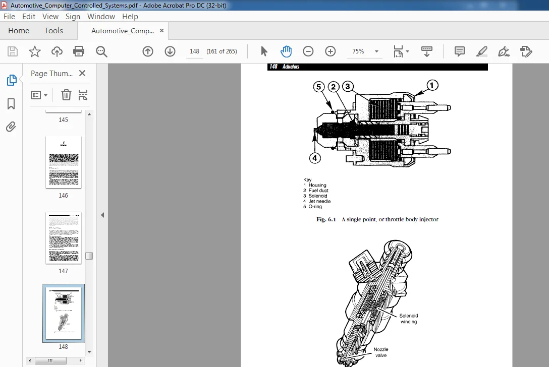
6.2 Petrol engine fuel injectors................................................160
6.2.1 SINGLE POINT INJECTION................................................160
6.2.2 MULTI-POINT PETROL INJECTION..........................................160
6.3 Testing of petrol injectors.................................................162
6.3.1 PEAK AND HOLD.........................................................162
6.3.2 CONVENTIONAL SWITCHING TO EARTH.......................................163
6.3.3 PULSE WIDTH MODULATED INJECTORS.......................................165
6.3.4 FURTHER INJECTOR TESTS................................................167
6.4 Exhaust gas recirculation...................................................167
6.4.1 TESTING THE EGR SENSOR................................................168
6.5 Petrol engine idle speed control............................................168
6.5.1 STEPPER MOTOR-OPERATED VALVE..........................................170
6.5.2 SOLENOID-OPERATED VALVE...............................................173
6.6 Ignition system.............................................................174
6.7 ABS actuators...............................................................174
6.8 A clamping diode............................................................175
6.9 Electronic unit injectors...................................................176
6.10 Review questions...........................................................178
7 Diagnostic techniques.............................................................181
7.1 Circuit testing.............................................................181
7.2 Vehicle specific details....................................................185
7.3 The 'six-steps' approach....................................................186
7.4 Skills required for effective diagnosis.....................................187
7.5 An approach to fault finding................................................188
7.6 Emissions related testing...................................................192
7.6.1 OXYGEN SENSOR.........................................................192
7.6.2 KNOCK SENSORS.........................................................199
7.6.3 AIR FLOW METERS.......................................................200
7.6.4 THROTTLE POSITION SWITCHES............................................203
7.6.5 A COOLANT TEMPERATURE SENSOR..........................................205
7.6.6 MANIFOLD ABSOLUTE PRESSURE SENSOR (MAP) TESTS.........................208
7.7 Ignition system tests.......................................................211
7.7.1 TESTS ON DISTRIBUTORLESS IGNITION DIS.................................211
7.8 Diesel injection............................................................213
7.8.1 TESTING THE INJECTION POINT ADVANCE...................................215
7.9 Sensor tests on other systems...............................................215
7.9.1 ABS WHEEL SPEED SENSORS...............................................216
7.9.2 TESTING THE RIDE HEIGHT CONTROL SENSOR................................219
7.10 Intermittent faults........................................................220
7.10.1 FLIGHT RECORDER (DATA LOGGER) FUNCTION...............................221
7.11 Summary....................................................................222
7.12 Review questions...........................................................223
8 Additional technology.............................................................225
8.1 Partial and absolute pressures..............................................225
8.2 The piezoelectric effect....................................................226
8.3 Liquid crystal displays.....................................................227
8.4 Countering cross-talk.......................................................229
8.5 Logic devices...............................................................229
8.5.1 THE RTL NOR GATE......................................................229
8.5.2 TRUTH TABLES..........................................................230
8.5.3 THE SR (SET, RESET) FLIP-FLOP.........................................231
8.5.4 ANALOGUE TO DIGITAL CONVERSION........................................234
8.5.5 DIGITAL TO ANALOGUE CONVERSION........................................235
8.6 OBD II......................................................................236
8.6.1 FUEL SYSTEM LEAKAGE...................................................237
8.6.2 SECONDARY AIR INJECTION...............................................238
8.6.3 FREEZE FRAMES.........................................................239
8.6.4 STANDARDIZED FAULT CODES..............................................239
8.7 Computer performance (MIPS).................................................240
8.8 Supplementary restraint systems (SRS).......................................240
8.8.1 HANDLING SRS COMPONENTS...............................................243
8.9 The coded ignition key......................................................244
8.10 Fault tracing..............................................................245
8.11 Precautions when working with computer controlled systems..................245
8.12 Variable capacitance sensor................................................246
8.13 Optoelectronics............................................................247
8.14 Review questions...........................................................248
Appendix............................................................................250
A.1 Companies who supply equipment and diagnostic data..........................250
A.2 Answers to review questions.................................................250
A.3 OBD II standard fault codes.................................................251
Index...............................................................................262
PLEASE NOTE:
This is the same manual used by the dealers to diagnose and troubleshoot your vehicle
You will be directed to the download page as soon as the purchase is completed. The whole payment and downloading process will take anywhere between 2-5 minutes
Need any other service / repair / parts manual, please feel free to contact [email protected] . We still have 50,000 manuals unlisted
SK
✹
What Our Customers Say
★★★★★Live reviews from customers
Loading customer reviews...
🌟 Related Products
Discover more professional manuals for your equipment