Baxter Flo-Gard 6200 Service Manual PDF Download
Original price was: $95.00.$18.95Current price is: $18.95.
Complete factory service manual for Baxter Travenol Flo-Gard 6200 volumetric infusion pump. Comprehensive flow rate calibration, occlusion pressure testing, air-in-line detector service, electrical safety testing, alarm system verification, battery replacement, and preventive maintenance schedules. Includes detailed schematics, troubleshooting flowcharts, component replacement procedures, and biomedical testing protocols. Essential resource for biomedical technicians servicing critical care infusion equipment.
Description
Baxter Flo-Gard 6200 Service Manual PDF Infusion Pump Repair Guide Download
Description
File Details
- Manual Name: Baxter Travenol Flo-Gard 6200 Volumetric Infusion Pump Service Manual
- Model Covered: Baxter Flo-Gard 6200 Infusion System
- Application: Critical care infusion pump service and repair
- PDF Quality: High-resolution factory original documentation
- Total Pages: 172 pages
Complete Service Manual Coverage
This Baxter Flo-Gard 6200 service manual provides comprehensive factory-authorized service procedures, calibration protocols, electrical safety testing, and troubleshooting guidelines for biomedical equipment technicians (BMETs) maintaining life-critical infusion delivery systems. Essential technical documentation for hospitals, clinics, and biomedical service organizations responsible for patient safety in IV therapy delivery.
Major Service Sections
Section 1: Safety Information & Warnings
Service Safety Requirements
- Electrical safety precautions for service personnel
- ESD (Electrostatic Discharge) protection protocols
- Patient safety considerations during maintenance
- Decontamination requirements before service
- Infection control procedures
- Biological hazard warnings
- Pressure system safety warnings
- Battery handling and disposal safety
- Service personnel qualification requirements
Regulatory & Standards Compliance
- FDA 510(k) clearance information
- IEC 60601-1 Medical Equipment Safety compliance
- IEC 60601-1-2 EMC (Electromagnetic Compatibility) standards
- IEC 60601-2-24 Infusion Pump specific requirements
- UL 2601-1 certification
- CSA C22.2 No. 601.1 certification
- Applied part classification: CF (Cardiac Floating)
- Defibrillator protection classification
Device Overview & Intended Use
| Specification | Flo-Gard 6200 |
|---|---|
| Pump Type | Volumetric linear peristaltic |
| Flow Rate Range | 0.1 to 999 mL/hr |
| VTBI Range | 0.1 to 9999 mL |
| Flow Accuracy | ±5% (between 5-999 mL/hr) |
| Bolus Rate | Up to 1200 mL/hr |
| Pressure Range | 50 to 1100 mmHg (adjustable) |
| Air-in-Line Detection | 50 microliters minimum |
| KVO (Keep Vein Open) Rate | 0.1 to 5.0 mL/hr (programmable) |
| Battery Type | Sealed lead-acid rechargeable |
| Battery Life | 4 hours at 125 mL/hr (typical) |
| AC Input | 100-240 VAC, 50/60 Hz, 1.5A |
| Operating Temperature | 10°C to 40°C (50°F to 104°F) |
| Storage Temperature | -25°C to 70°C (-13°F to 158°F) |
| Humidity Range | 20% to 95% RH non-condensing |
| Weight | 3.6 kg (8 lbs) |
| Dimensions | 305 x 127 x 140 mm (12″ x 5″ x 5.5″) |
Section 2: System Description & Theory of Operation
Pump Mechanism Overview
- Linear peristaltic pumping principle
- Stepper motor control system
- Tubing compression mechanism
- Cam and finger assembly operation
- Disposable IV set requirements
- Flow rate calculation algorithms
- Volume delivered tracking
Electronic System Architecture
- Microprocessor control system
- Analog-to-digital conversion
- Stepper motor driver circuits
- Sensor input processing
- Display driver circuitry
- Alarm processing and prioritization
- Power management system
- Battery monitoring circuits
Sensor Systems
Pressure Sensing System
- Strain gauge pressure transducer
- Pressure measurement range: 0-1500 mmHg
- Pressure alarm limits: 50-1100 mmHg (user adjustable)
- Occlusion detection algorithms
- Upstream and downstream monitoring
- Pressure transducer calibration requirements
Air-in-Line Detection System
- Ultrasonic air bubble detection
- Detection sensitivity: 50 microliters
- Dual ultrasonic transducers (transmitter/receiver)
- Signal processing algorithms
- Foam and micro-bubble discrimination
- Detector self-test procedures
Drop Sensor System (if equipped)
- Optical drop counting mechanism
- Drop size calibration
- Free-flow detection capability
- Secondary volume verification
Door Closure Detection
- Door latch switch operation
- Safety interlock function
- Anti-free-flow mechanism
- Door position verification
Section 3: Flow Rate Calibration Procedures
Calibration Equipment Required
- Precision analytical balance (±0.01g accuracy, NIST traceable)
- Graduated cylinder (250 mL minimum)
- Stopwatch or timer (±0.1 second accuracy)
- Manufacturer-approved IV administration sets
- Distilled water at room temperature (20-25°C)
- Calibration weight set for balance verification
Flow Rate Calibration Protocol
Gravimetric Calibration Method
| Flow Rate | Test Duration | Expected Volume | Tolerance |
|---|---|---|---|
| 1.0 mL/hr | 60 minutes | 1.0 mL (1.0 g) | ±5% (0.95-1.05 g) |
| 5.0 mL/hr | 30 minutes | 2.5 mL (2.5 g) | ±5% (2.38-2.63 g) |
| 25 mL/hr | 12 minutes | 5.0 mL (5.0 g) | ±5% (4.75-5.25 g) |
| 100 mL/hr | 6 minutes | 10.0 mL (10.0 g) | ±5% (9.5-10.5 g) |
| 500 mL/hr | 3 minutes | 25.0 mL (25.0 g) | ±5% (23.75-26.25 g) |
| 999 mL/hr | 3 minutes | 49.95 mL (49.95 g) | ±5% (47.45-52.45 g) |
Calibration Test Procedure Steps
- Prime IV set completely, ensure no air bubbles
- Program pump to desired test flow rate
- Set VTBI to ensure continuous delivery during test
- Place graduated cylinder on calibrated balance, tare to zero
- Start pump and simultaneously start timer
- Allow infusion to proceed for specified test duration
- Stop pump and timer simultaneously
- Record delivered weight in grams (1 mL H₂O = 1 g @ 20°C)
- Calculate actual flow rate: (Weight ÷ Time) × 60 = mL/hr
- Compare to programmed rate, verify within ±5% tolerance
- Document results on calibration certificate
Flow Rate Adjustment Procedures
- Accessing service calibration mode
- Software calibration constants
- Stepper motor timing adjustments
- Verification after adjustment
- Calibration data storage in EEPROM
Volumetric Accuracy Testing
- VTBI (Volume To Be Infused) accuracy verification
- Short-term accuracy (1 hour test periods)
- Long-term accuracy (8 hour test periods)
- Start-up bolus measurement
- End-of-infusion accuracy
Section 4: Occlusion Pressure Testing
Occlusion Pressure Calibration
Equipment Required
- Precision pressure gauge (0-1500 mmHg, ±1% accuracy)
- T-connector for pressure monitoring
- IV administration set
- Hemostat or clamp
- Pressure reference standard (mercury manometer or digital)
Occlusion Pressure Test Procedure
| Set Pressure | Expected Response | Tolerance |
|---|---|---|
| 50 mmHg | Alarm within 30 seconds | ±10 mmHg |
| 300 mmHg | Alarm within 30 seconds | ±15 mmHg |
| 600 mmHg | Alarm within 30 seconds | ±20 mmHg |
| 900 mmHg | Alarm within 30 seconds | ±25 mmHg |
| 1100 mmHg | Alarm within 30 seconds | ±30 mmHg |
Test Protocol Steps
- Connect pressure gauge via T-connector downstream from pump
- Prime system, close door, start infusion at 125 mL/hr
- Program occlusion pressure limit to test value
- Clamp IV tubing downstream from pressure measurement point
- Observe pressure rise on reference gauge
- Verify pump alarms when set pressure is reached
- Note actual pressure at alarm activation
- Verify pressure reading accuracy within tolerance
- Release clamp, clear alarm, repeat for each test point
- Document results
Pressure Transducer Calibration
- Zero pressure calibration (atmospheric reference)
- Span calibration using known pressure source
- Linearity verification across range
- Offset adjustment procedures
- Gain adjustment procedures
- Transducer replacement criteria
Section 5: Air-in-Line Detector Testing
Air Detection Sensitivity Testing
Equipment Required
- Microliter syringe (50-100 μL capacity)
- IV administration set
- Air-free saline or distilled water
- Air bubble injection port
Air Detection Test Protocol
| Air Volume | Expected Response |
|---|---|
| 25 μL | No alarm (below threshold) |
| 50 μL | Alarm activation required |
| 75 μL | Alarm activation required |
| 100 μL | Alarm activation required |
Test Procedure Steps
- Prime IV set completely with saline, ensure no air bubbles
- Install set in pump, close door
- Position air detector on set tubing per manufacturer guidelines
- Start infusion at 125 mL/hr
- Using microliter syringe, inject precise air volume into tubing upstream of detector
- Observe for alarm activation as air bubble passes detector
- Record air volume that triggers alarm
- Verify 50 μL minimum detection sensitivity
- Test foam detection (should not cause false alarms)
- Document results
Air Detector Calibration
- Ultrasonic transducer alignment
- Signal amplitude adjustment
- Threshold level calibration
- Self-test verification
- Detector cleaning procedures
- Transducer replacement procedures
Section 6: Alarm System Verification
Alarm Priority Classifications
High Priority Alarms (Continuous tone, red LED)
- Air-in-line detected
- Occlusion pressure exceeded
- Door open during infusion
- Upstream occlusion
- Infusion complete (if programmed critical)
- Battery depleted (<5 minutes remaining)
- System failure
Medium Priority Alarms (Intermittent tone, yellow LED)
- Infusion complete (normal)
- Low battery (<30 minutes remaining)
- KVO mode active
- Distal occlusion warning
Low Priority Alarms (Single beep, advisory messages)
- Near end of infusion
- Setting confirmation requests
- Information messages
Alarm Audio Testing
Sound Pressure Level Verification
- Test equipment: Sound level meter (Type 2 minimum)
- Measurement distance: 1 meter from front panel
- Ambient noise level: <45 dBA
- Required alarm level: >45 dBA (IEC 60601-1-8)
- Typical alarm level: 55-65 dBA
- Frequency range: 500-2000 Hz
Alarm Functional Testing Checklist
- ☐ Air-in-line alarm activation and audio verification
- ☐ Occlusion alarm at multiple pressure settings
- ☐ Door open alarm when door opened during infusion
- ☐ Battery low alarm (simulate low battery condition)
- ☐ Infusion complete alarm
- ☐ KVO alarm (if KVO enabled)
- ☐ System error alarms
- ☐ Alarm volume adjustment functionality
- ☐ Alarm mute function (maximum 2 minutes per IEC 60601-1-8)
- ☐ Visual alarm indicators (LEDs) for each alarm condition
- ☐ Remote alarm output (if equipped with nurse call)
Nurse Call Interface Testing (if equipped)
- Relay contact closure verification
- Alarm condition transmission
- Contact rating: 30V DC, 0.5A maximum
- Connector pinout verification
- Isolation testing between pump and nurse call circuits
Section 7: Display & User Interface Testing
Display System Service
- LCD display module specifications
- Backlight operation and brightness
- Display segment testing (all segments on)
- Pixel functionality verification
- Display contrast adjustment
- Temperature effects on display
- Display module replacement procedures
Keypad Testing
- Membrane switch functionality
- Key response verification
- Tactile feedback testing
- Key bounce elimination
- Key repeat function testing
- Audible key click verification
- Keypad bezel replacement
LED Indicator Testing
- Power LED (green) – AC power connected
- Battery LED (amber) – Battery operation
- Charging LED – Battery charging status
- Alarm LEDs (red/yellow) – Alarm status
- Infusing LED – Active delivery indication
- LED brightness verification
- LED driver circuit testing
Section 8: Battery System Service
Battery Specifications
- Battery type: Sealed lead-acid (SLA) 12V
- Capacity: 2.3 Ah minimum
- Battery life: 400-500 charge cycles typical
- Expected service life: 3-5 years
- Operating temperature: 0°C to 40°C
- Charge time: 16-20 hours (fully depleted to full charge)
- Charge current: 200 mA (trickle charge), 500 mA (fast charge)
Battery Performance Testing
Battery Capacity Test Protocol
- Fully charge battery (24 hours on AC power)
- Disconnect AC power, operate on battery only
- Set flow rate to 125 mL/hr (standard test condition)
- Record start time
- Allow pump to operate until low battery alarm
- Record time when alarm activates
- Minimum acceptable runtime: 3 hours at 125 mL/hr
- Battery replacement required if <3 hours runtime
Battery Charging System Testing
- Charging voltage measurement: 13.6-14.4 VDC
- Charging current measurement during fast charge
- Trickle charge current verification
- Charge termination verification (full charge detection)
- Overcharge protection testing
- Battery temperature monitoring during charge
Battery Replacement Procedures
- Battery compartment access
- Connector removal and installation
- Battery polarity verification
- Battery disposal requirements (lead-acid recycling)
- Replacement battery part number verification
- Post-replacement charging and testing
Battery Safety Warnings
- Lead-acid battery handling precautions
- Acid spill procedures
- Short circuit prevention
- Proper disposal/recycling requirements
- DOT/IATA shipping regulations for replacement batteries
Section 9: Electrical Safety Testing
IEC 60601-1 Electrical Safety Tests
Earth/Ground Continuity Test
- Test current: 25A AC (alternative: 10A DC)
- Maximum resistance: 0.2 Ω (between AC cord ground and chassis)
- Test duration: 5 seconds minimum
- Measurement points: AC plug ground pin to any accessible metal part
- Pass/fail criteria: <0.2 Ω
Enclosure Leakage Current Test
- Normal condition: <100 μA
- Single fault condition (ground open): <500 μA
- Test configuration: AC mains applied at 110% rated voltage
- Measurement: Between all accessible parts and ground
- Applied part testing: CF type limits apply
Patient Leakage Current Test (Applied Parts)
- Normal condition: <10 μA (CF type)
- Single fault condition: <50 μA (CF type)
- Test voltage: 110% rated mains voltage
- Measurement network: Per IEC 60601-1 (1kΩ + 0.15μF)
- Test all patient-connected parts (pressure port, air detector contact points)
Patient Auxiliary Current Test
- Between applied parts: <100 μA normal, <500 μA fault
- Applied part to ground: <100 μA normal, <500 μA fault
- Test conditions: Mains on applied part (fault simulation)
Dielectric Strength Test (Hi-Pot)
- Test voltage: 1500 VAC (60 seconds) or 2121 VDC
- Applied between: AC input and accessible parts
- Creepage and clearance verification
- Pass criteria: No breakdown, flashover, or arcing
- WARNING: Potentially destructive test, perform only when required
Defibrillator Protection Testing
- Applied part withstand: 5000V defibrillator pulse
- Recovery time: <10 seconds after discharge
- Function verification after defibrillator discharge
- No sustained damage to pump or sensors
Section 10: Preventive Maintenance Schedule
Maintenance Interval Summary
Before Each Use (Clinical Staff)
- Visual inspection for damage
- Power-on self-test observation
- Battery indicator check
- Basic function test (start/stop)
- Tubing installation verification
- Alarm audio test
Monthly Inspection (Clinical Engineering)
- Complete function testing
- Alarm system verification
- Display and keypad functionality
- Battery operation test (minimum 30 minutes)
- Exterior cleaning and decontamination
- Label and decal inspection
- Accessory inspection (pole clamp, power cord)
Semi-Annual Preventive Maintenance
- Flow rate calibration verification (minimum 3 test points)
- Occlusion pressure accuracy testing
- Air-in-line detector sensitivity test
- Alarm audio level measurement
- Battery runtime test (full discharge cycle)
- Electrical safety testing (ground continuity, leakage current)
- Mechanical inspection (door latch, tubing retainer)
- Software version verification
- Preventive maintenance sticker update
Annual Comprehensive Maintenance
- Complete flow rate calibration (all test points)
- Occlusion pressure calibration
- Air detector calibration verification
- Complete electrical safety test battery per IEC 60601-1
- Battery capacity test and replacement if <80% capacity
- Internal component inspection
- Firmware update if available
- Complete documentation update
- Annual inspection certification sticker
Battery Replacement Criteria
- Runtime <3 hours at 125 mL/hr
- Age >5 years
- Physical damage or leakage
- Charge acceptance degradation
- Failure of capacity test
Section 11: Troubleshooting Procedures
System-Level Troubleshooting
| Symptom | Possible Cause | Corrective Action |
|---|---|---|
| Unit won’t power on | Dead battery, no AC power | Connect AC power, test outlet |
| Power switch failure | Test switch continuity, replace if needed | |
| Fuse blown | Check/replace fuse, investigate cause | |
| Power supply failure | Test DC voltages, replace power supply | |
| Display blank | Backlight failure | Test backlight voltage, replace inverter |
| Display cable disconnected | Reseat display connector | |
| Display module failure | Replace display module | |
| Contrast adjustment | Adjust contrast potentiometer | |
| Pump won’t start | Door not fully closed | Verify door latch engagement |
| No IV set installed | Install compatible IV set | |
| System error | Run diagnostics, clear error codes | |
| Inaccurate flow rate | Incorrect calibration | Perform flow rate calibration |
| Worn pump mechanism | Inspect/replace cam and finger assembly | |
| IV set compatibility issue | Use manufacturer-approved sets only | |
| Tubing pinched or kinked | Inspect tubing path, reload set | |
| Occlusion alarm – no blockage | Pressure sensor out of calibration | Calibrate pressure transducer |
| Air in pressure sensing line | Prime system, eliminate air | |
| Kink in tubing upstream | Inspect entire fluid path | |
| Pressure limit set too low | Increase pressure alarm limit | |
| Air-in-line alarm – no air visible | Detector sensitivity too high | Calibrate air detector |
| Foam in solution | Use defoaming agent, filter solution | |
| Microbubbles in fluid | Allow fluid to degas before use | |
| Detector misalignment | Verify detector positioning on tubing | |
| Battery won’t charge | Charger circuit failure | Test charging voltage, replace charger |
| Battery end of life | Test battery capacity, replace battery | |
| Battery connections corroded | Clean contacts, verify connections | |
| No alarm sounds | Speaker failure | Test speaker output, replace speaker |
| Audio circuit fault | Test audio amplifier, repair/replace | |
| Volume set to zero | Adjust volume setting | |
| Erratic operation | Electrical interference | Test in different location, check grounding |
| Loose internal connections | Inspect/reseat all connectors | |
| Software corruption | Reload firmware |
Diagnostic Mode Procedures
- Service menu access code entry
- Self-test routines execution
- Sensor raw value monitoring
- Motor control diagnostics
- Memory test procedures
- Error log retrieval and interpretation
- Factory reset procedures
Section 12: Component Replacement Procedures
Major Assembly Replacement
Pump Mechanism Replacement
- Disassembly sequence for accessing pump mechanism
- Cam and finger assembly removal
- Stepper motor disconnection
- Drive coupling alignment
- Reassembly and alignment verification
- Post-replacement calibration requirements
Pressure Transducer Replacement
- Transducer location and mounting
- Fluid line disconnection procedures
- Electrical connector removal
- New transducer installation
- Air purging from pressure lines
- Calibration after replacement
Air Detector Assembly Replacement
- Detector mounting clip removal
- Electrical connector disconnection
- Alignment pin positioning
- Transducer pair alignment verification
- Calibration and sensitivity testing
Power Supply Module Replacement
- AC input disconnection
- DC output verification before removal
- Module mounting screw locations
- Connector identification and routing
- Output voltage verification after installation
- Load testing procedures
Display Module Replacement
- Bezel removal procedures
- Display cable disconnection (ribbon cable handling)
- Display mounting hardware removal
- New display installation and cable connection
- Display test pattern verification
- Contrast and brightness adjustment
Battery Replacement
- Battery compartment access
- Battery connector removal (polarity warning)
- Mounting bracket or retention system
- New battery installation
- Initial charging procedure
- Capacity verification test
Section 13: Schematics & Technical Diagrams
Electrical Schematics
- Main processor board schematic
- Power supply detailed schematic
- Stepper motor driver circuit
- Sensor input circuits (pressure, air detector)
- Display driver circuit
- Keypad interface circuit
- Battery charging circuit
- Alarm output circuits (audio and nurse call)
Block Diagrams
- System architecture overview
- Signal flow diagrams
- Power distribution diagram
- Microprocessor peripheral connections
- Sensor interface block diagram
Mechanical Drawings
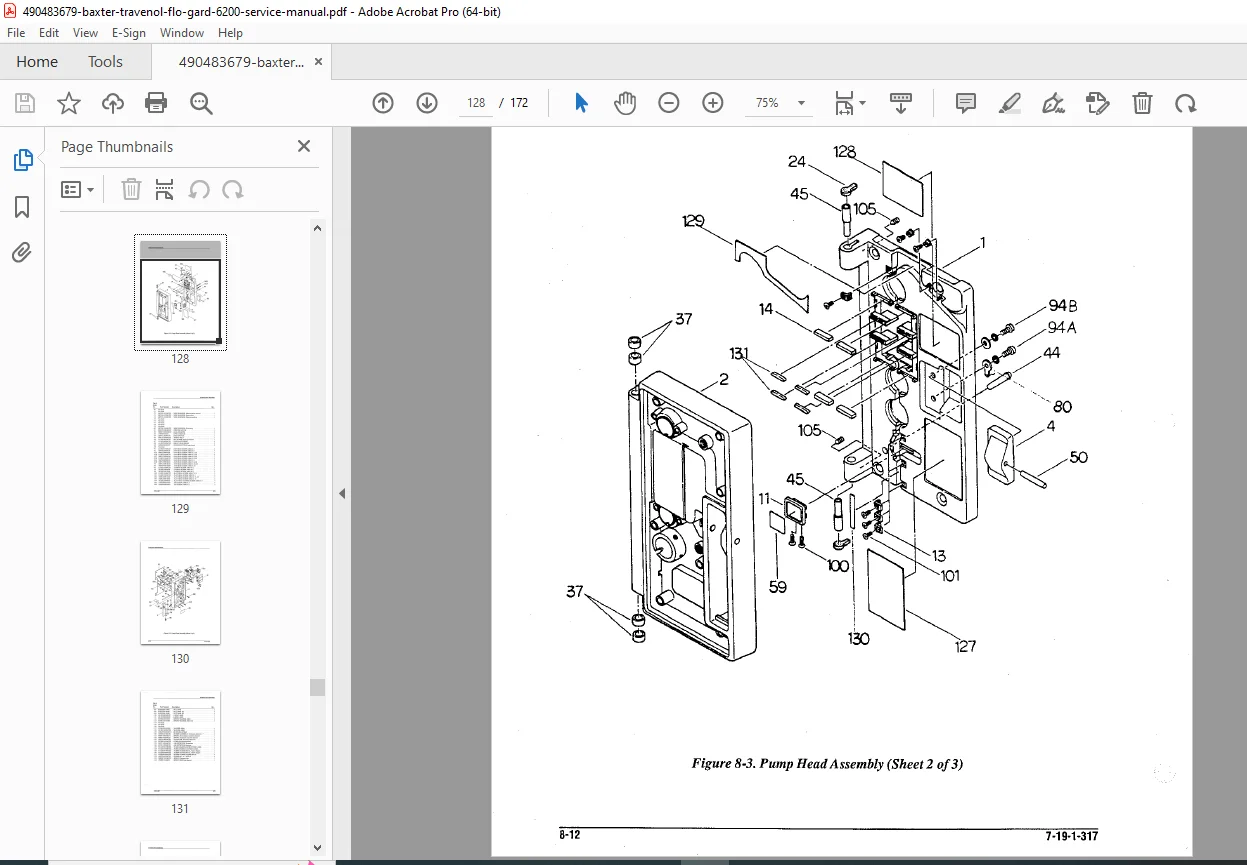
- Pump mechanism assembly
- IV set loading path
- Door latch mechanism
- Housing assembly exploded view
- Mounting bracket dimensions
Component Location Diagrams
- Main PCB component locations
- Test point locations and functions
- Adjustment potentiometer locations
- Connector pinout diagrams
- Fuse locations and ratings
Section 14: IV Administration Set Compatibility
Approved IV Set Specifications
- Tubing outer diameter: 4.0-4.5 mm
- Tubing wall thickness specifications
- Tubing material: PVC or polyethylene
- Drip chamber requirements
- Luer lock/slip tip compatibility
- Inline filter compatibility
- Maximum tubing length considerations
Manufacturer-Approved Sets
- Baxter/Travenol standard sets (part numbers listed)
- Third-party compatible sets (verified brands)
- Pediatric/neonatal sets (special considerations)
- Blood administration sets (specific protocols)
- Sets to avoid (compatibility issues)
Set Loading Instructions
- Door opening procedure
- Tubing routing through pump mechanism
- Door closure and latching verification
- Anti-free-flow clip engagement
- Air detector positioning
- Drip chamber fill level requirements
Section 15: Software & Firmware
Software Version Identification
- Accessing system information screen
- Version number format and interpretation
- Revision history and bug fixes
- Feature changes in versions
Firmware Update Procedures
- Update file acquisition from manufacturer
- Communication interface requirements (RS-232 or USB)
- Update software installation on service computer
- Pump connection procedures
- Upload process and duration
- Verification after update
- Rollback procedures if update fails
Configuration Parameters
- User-settable parameters and ranges
- Service-level configuration options
- Hospital-specific default settings
- Safety limit configurations
- Drug library programming (if equipped)
Section 16: Cleaning & Decontamination
Routine Cleaning Procedures
- Approved cleaning agents (quaternary ammonium compounds)
- Surface disinfection protocols
- Spill cleanup procedures (blood, IV fluids)
- Keypad and display cleaning
- Exterior housing cleaning
- Ventilation port cleaning
- Pole clamp maintenance
Decontamination Before Service
- Biohazard assessment requirements
- Disinfection protocols per OSHA standards
- EPA-registered disinfectant use
- Contact time requirements
- Decontamination verification
- Biohazard labeling if not decontaminated
Materials to Avoid
- Abrasive cleaners (damage to plastic housing)
- Acetone or strong solvents
- Bleach solutions >10% concentration
- Phenolic compounds
- Steam sterilization (not compatible)
Section 17: Parts List & Ordering Information
Field Replaceable Units (FRUs)
- Main circuit board assembly (with processor)
- Power supply module
- Display assembly (LCD with backlight)
- Keypad assembly (membrane switch)
- Pump mechanism assembly (complete)
- Stepper motor
- Pressure transducer
- Air-in-line detector assembly
- Speaker/buzzer
- Battery pack (sealed lead-acid)
- Door latch assembly
- Anti-free-flow device
- AC power cord (hospital grade)
- Pole clamp assembly
Service Parts & Consumables
- Fuses (type and rating specifications)
- Mechanical components (springs, clips, brackets)
- Cable assemblies (internal)
- Screws and fasteners
- Labels and decals (safety, operational, calibration)
- Service kit (common repair parts bundled)
Section 18: Regulatory & Quality System Requirements
FDA Medical Device Reporting (MDR)
- Reportable events and timelines
- Serious injury or death reporting
- Malfunction reporting requirements
- Manufacturer notification procedures
Quality System Requirements
- Service documentation requirements
- Calibration traceability (NIST standards)
- Service record retention (7 years minimum)
- Technician training and competency
- Test equipment calibration status
- Out-of-tolerance reporting
Risk Management Considerations
- Failure modes and effects analysis (FMEA)
- Clinical risk assessment
- Preventive maintenance frequency justification
- Critical component identification
Why This Service Manual Is Essential
Biomedical equipment technicians rely on this Baxter Flo-Gard 6200 service manual for accurate calibration procedures, electrical safety testing protocols, and factory-authorized repair procedures to maintain patient safety in critical IV therapy delivery. This life-critical medical device requires precise maintenance to prevent medication errors, air embolism, and fluid management complications.
Essential for:
- Hospital Clinical Engineering Departments: In-house fleet maintenance
- Biomedical Equipment Service Companies: Multi-facility service contracts
- Independent Biomedical Technicians: Field service and emergency repairs
- Medical Equipment Rental Companies: Fleet maintenance and safety compliance
- Nursing Education: Understanding equipment for proper clinical use
- Risk Management: Equipment investigation and incident analysis
Patient Safety Critical:
- Accurate medication delivery prevents under/over-dosing
- Occlusion detection prevents IV infiltration
- Air-in-line detection prevents air embolism
- Battery backup ensures continuous therapy
- Alarm system reliability enables timely intervention
- Electrical safety prevents patient electrical hazards
Regulatory Compliance:
- Joint Commission equipment maintenance standards
- CMS Conditions of Participation compliance
- State health department inspection requirements
- ECRI Institute safety recommendations
- FDA medical device tracking requirements
- OSHA bloodborne pathogen standards
- NFPA 99 Health Care Facilities Code
Instant Digital Access
Download immediately after purchase and access complete factory service procedures for the Baxter Flo-Gard 6200 infusion pump. Searchable PDF format enables quick navigation to calibration protocols, electrical safety tests, and critical troubleshooting procedures. Print relevant sections for biomedical shop reference or view on tablet during hospital equipment maintenance rounds.
Ensure patient safety and medication delivery accuracy – download this comprehensive 168-page Baxter Flo-Gard 6200 service manual now and perform professional biomedical equipment maintenance with manufacturer-authorized calibration procedures, electrical safety testing protocols, and life-critical system verification!