Belarus 952.5 Tractor Operator’s Manual – PDF DOWNLOAD
Original price was: $87.95.$25.95Current price is: $25.95.
Belarus 952.5 Tractor Operator’s Manual – PDF DOWNLOAD
Description
Belarus 952.5 Tractor Operator’s Manual – PDF DOWNLOAD
IMAGES PREVIEW OF THE MANUAL:


DESCRIPTION:
Belarus 952.5 Tractor Operator’s Manual – PDF DOWNLOAD
Introduction :
The present manual is designed for studying the structure, operation rules and maintenance of tractors “BELARUS-952.5”. Scrutinize this manual. It will help you to study the rules of correct operation and maintenance. Failure to follow this instruction can lead to operator’s injury or a breakdown of a tractor.
- Operation of a tractor, its maintenance and repair shall be carried out only by employees, familiar with all of its parameters and characteristics and informed about necessary safety requirements to prevent casualties.
- In connection with constant development of the tractor some changes, which are not depicted in the present manual, can be introduced in the structure of certain units and parts. Any arbitrary changes made by a consumer release the manufacturer from responsibility for possible further injuries to the operator and tractor breakdown.
TABLE OF CONTENTS:
Belarus 952.5 Tractor Operator’s Manual – PDF DOWNLOAD
1 TRACTOR DESCRIPTION AND OPERATION 11
1 1 Tractor assignment 11
1 2 Technical specifications 12
1 3 Tractor composition 15
1 4 Vibration level at the operator’s working place of the tractor “BELARUS-952 5” 18
1 5 Noise level at the operator’s working place of the tractor “BELARUS-952 5” 18
1 6 Tractor and its component marking 18
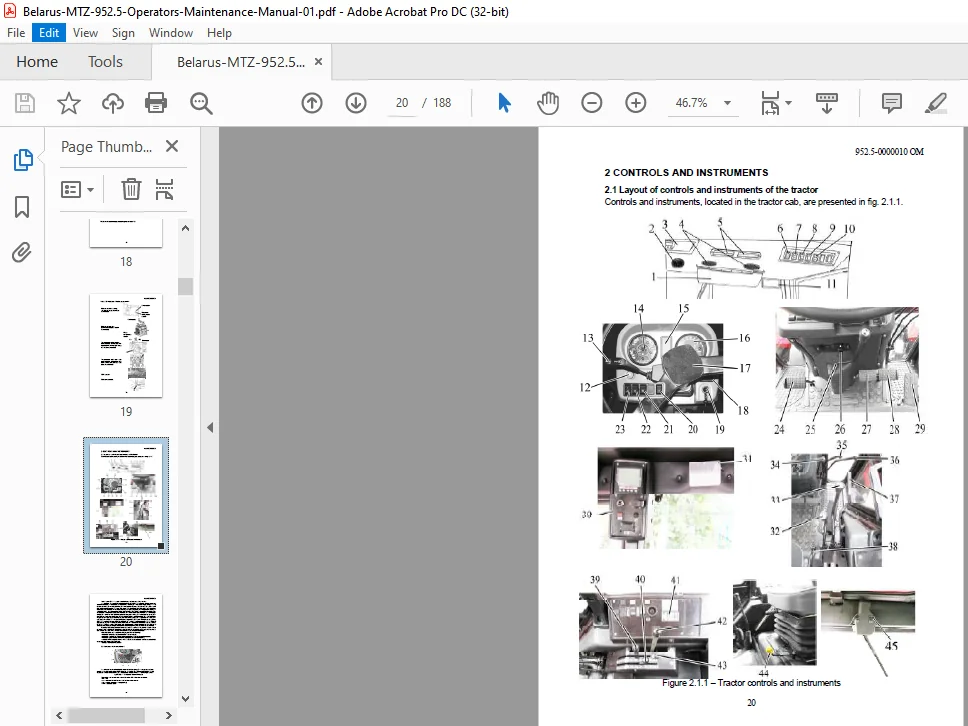
2 CONTROLS AND INSTRUMENTS 20
2 1 Layout of controls and instruments of the tractor 20
2 2 Switches of instrument board 21
2 3 Upper shield unit of button switches and rear wiper switch 23
2 4 Cab heater and fan control 24
2 5 Conditioner control 25
2 5 1 Conditioner control in conditioning mode 25
2 5 2 Conditioner control in a heating mode 25
2 5 3 Cab ventilation 26
2 6 Instrument board 27
2 7 Pilot lamps unit 28
2 7 1 General information 28
2 7 2 Functioning algorithm of pilot lamp to indicate operation of heating plugs 29
2 8 Integrated indicator 30
2 8 1 General information 30
2 8 2 Assignment and operation principle of integrated indicator gauges 30
2 8 3 Pilot lamps of the integrated indicator 33
2 8 4 Description of testing the indicator performance 34
2 8 5 Programming panel of integrated indicator 34
2 9 Engine control panel 36
2 9 1 General information 36
2 9 2 Information display 36
2 9 2 1 General information 36
2 9 2 2 Adjustment of brightness and sharpness of the information display 37
2 9 2 3 Call up of changeable images and parameters on the screen of the information
display 37
2 10 Steering 40
2 10 1 General information 40
2 10 2 Steering wheel adjustments 40
2 11 Parking brake control 40
2 12 Handle for fuel feed manual control 40
2 13 Tractor pedals 41
2 14 Gear shifting 41
2 14 1 General information 41
2 14 2 Gears shifting in the transmission with a double-lever GB control and speedincrease
gear unit 41
2 14 3 Gear shifting in transmission with a single-lever GB control and speed-increase
gear unit 42
2 14 4 Gears shifting in transmission with double-lever GB control and reverse gear unit
44
2 14 5 Gears shifting in the transmission with a single-lever GB control and reverse gear
unit 45
2 15 Control panel for rear axle DL and rear PTO 47
952 5-0000010 OM
4
2 16 FDA drive control 48
2 17 Rear power take-off shaft control 49
2 17 1 Lever shifting rear PTO from continuous drive to ground-speed drive 49
2 17 2 Rear power take-off shaft engagement 49
2 17 3 Two-speed continuous drive of rear PTO switch 50
2 17 4 Tractor operation without use of rear PTO 50
2 18 Rear lift linkage control with hydraulic lift 50
2 18 1 RLL control elements with hydraulic lift 50
2 18 2 General information about control rules for RLL with hydraulic lift 51
2 19 HLL pump control 52
2 20 Hydraulic lift linkage distribution valve sections (remote cylinders) control 52
2 20 1 Remote hydraulic cylinders with distribution valve RP70-1221 (RP70-1221 C) or
RP70-1221 1 (RP70-1221 1 C) or RS213Mita (RS213Belarus) installed control by
means of levers 52
2 20 2 Remote hydraulic cylinders with distribution valve RP70-622 or (RP70-1221TC)
installed control by means of joystick and lever 54
2 21 Cutout fuses 55
2 21 1 General information 55
2 21 2 Fuses for electrical equipment system 55
2 21 3 Fuse for engine electronic control system 56
2 22 Cab locks and handles 60
2 22 1 Cab door locks 60
2 22 2 Left-side window opening 60
2 22 3 Rear window opening 61
2 22 4 Cab roof opening 61
2 22 5 Cab emergency exits 61
2 23 Seat and its adjustments 61
2 23 1 General information 61
2 23 2 Adjustments of BELARUS seat 62
2 23 3 Adjustments of Grammer seat 63
2 24 Controlling pneumatic system compressor 63
2 25 Connector elements of the electrical equipment 64
2 25 1 Socket to connect coupled agricultural equipment 64
2 25 2 Connection of additional electrical equipment of coupled machines 64
2 26 Creeper control 65
2 27 Controls of tractor equipped with RLL control system with draft control unit,
mechanical control of rear axle differential lock and rear PTO 66
2 27 1 General information 66
2 27 2 Mechanical control of rear axle differential lock 66
2 27 3 Rear PTO mechanical control 67
2 27 4 RLL fixing mechanism control in transport position 67
2 27 5 Adjustable implement lifting limiter 67
2 27 6 Rear PTO control with draft control unit 67
2 27 6 1 General information 67
2 27 6 2 Draft control unit operation providing draft, positional and depth control of
agricultural implements position 68
2 27 6 3 Draft control unit operation providing draft, positional, mixed and depth control
of agricultural implements position 71
2 27 7 Hydraulic hook or lowered link grippers control 72
952 5-0000010 OM
5
3 INTENDED USE OF TRACTOR 73
3 1 Safety measures to be taken preparing tractor for operation 73
3 2 Tractor use 74
3 2 1 Boarding the tractor 74
3 2 2 Preparing for start and starting the engine 74
3 2 3 Tractor motion start, GB shifting 75
3 2 4 Tractor stop 78
3 2 5 Engine stop 78
3 2 6 Leaving the tractor 78
3 2 7 PTO use 78
3 2 8 Selection of optimal inner pressure in tires depending on operational conditions
and load on tractor axles 80
3 2 8 1 Selection of optimal inner pressure in tires depending on operational conditions
and load on tractor axles 80
3 2 8 2 Tire inflation 81
3 2 9 Rear wheel track formation 82
3 2 9 1 Track formation of rear wheels, mounted on terminal hubs 82
3 2 9 2 Track formation of rear wheels, mounted on taper hubs 83
3 2 10 Rear wheel twinning 84
3 2 11 Front wheel track formation 85
3 2 11 1 General information 85
3 2 11 2 Front wheels track formation of the tractors equipped with FDA with planetary
cylindrical wheel-hub drives 85
3 2 11 3 Possible variants of front wheels track installation of the tractors, equipped with
FDA with taper wheel hubs and information on tires, mounted on tractors with FDA
72-2300020-А-04 87
3 3 Safety measures to be taken when operating the tractor 89
3 3 1 General safety measures to be taken when operating the tractor 89
3 3 2 Fire safety measures 92
3 4 Tractor final assembly and run-in 93
3 4 1 Tractor final assembly 93
3 4 2 Technical maintenance before tractor run-in 93
3 4 3 Tractor run-in 93
3 4 4 Technical maintenance during tractor run-in 94
3 4 5 Technical maintenance after tractor run-in 94
3 5 Emergency actions 95
4 COUPLING OF IMPLEMENTS 96
4 1 General information 96
4 2 Types of implements coupled with tractor “BELARUS-952 5” 97
4 3 Rear lift linkage 98
4 3 1 General information 98
4 3 2 Three-point rear lift linkage 98
4 3 3 RLL components adjustment rules 101
4 3 3 1 Buckles 101
4 3 3 1 1 General information 101
4 3 3 1 2 Telescopic buckles 101
4 3 3 1 3 Outer turnbuckles 103
4 3 3 1 4 Inner buckles 104
4 3 3 2 Lifting rod 105
4 3 3 3 Upper link 106
4 3 3 4 Lower links 106
4 3 3 4 1 General information 106
952 5-0000010 OM
6
4 3 3 4 2 Installation of crossbar and rear ends of split lower links in operation
position 107
4 3 4 Attachment of implements to a tractor 108
4 4 Drawbar hitches 109
4 4 1 General information 109
4 4 2 Drawbar hitch DH-2V (short towing yoke) 110
4 4 3 Drawbar hitch DH-ЗV (long towing yoke) 111
4 4 4 Drawbar hitch DH-2R (python) 112
4 4 5 Drawbar hitch DH-1М-01 (draw bar) 113
4 4 6 Drawbar hitch DH -1 (crossbar) 114
4 4 7 Drawbar hitch DH-2 (hydraulic hook) and combined drawbar DH-2М-02 (with
hydraulic hook in operation position and floating drawbar in additional position) 115
4 4 8 Combined drawbar DH-1M-02 (combined drawbar with floating drawbar in operating
position and hydraulic hook in additional position) 116
4 4 9 Drawbar hitch DH-1М (floating drawbar/pendulum) 116
4 4 10 Lowering link 116
4 4 11 Basic parameters and coupling dimensions of DH-1M-02 (combined drawbar
with floating drawbar (pendulum) in operating position, of DH-1M (floating drawbar) and
of lowering link) 117
4 4 12 Drawbar hitch DH-1ZH (crossbar) 118
4 4 13 Drawbar hitch DH-1ZH-01 (twin crossbar) 118
4 4 14 Repositioning of floating drawbar and hydraulic hook in combined drawbar 119
4 5 Usage patterns of tractor hydraulic system for driving of operated parts and other
elements of unitized hydraulically operated machines and aggregates 123
4 6 Front ballast weight installation 124
4 7 Trailer brake actuator 125
4 7 1 General information 125
4 7 2 Double-line pneumatic drive of trailer brakes 125
4 7 3 Hydraulic drive of trailer brakes 126
4 7 3 1 General information 126
4 7 3 2 Adjustment of hydraulic actuator of trailer brakes 127
4 8 Determination of PTO shaft and cardan shaft applicability 128
4 9 Features of application of PTO shafts and cardan shafts 128
4 10 Ways of changing of drawbar features and passing ability of the tractors 132
4 11 Features of the tractor application in special conditions 133
4 11 1 Tractor operation in areas with rugged topography 133
Possibility of the tractor application for haulage allocation for reserve 133
4 11 2 Application of substances for the purpose of chemical treatment 133
4 11 3 Operation in a forest 133
4 12 Finding of total weight, loads on the front and rear axles, tires holding capacity and
required minimum ballast 134
4 13 Possibility of front loader installation 136
4 13 1 General information 136
4 13 2 Safety measures at tractor “BELARUS-952 5” operation with loader installed 138
952 5-0000010 OM
7
5 MAINTENANCE 142
5 1 General instructions 142
5 2 Providing access to the components for maintenance services 144
5 3 Maintenance procedure 145
5 4 Scheduled maintenance servicing operations 148
5 4 1 Maintenance on a shift basis (SBMS) in every 8 – 10 hours of operation or
per shift 148
5 4 2 Maintenance services in every 125 hours of operation 154
5 4 3 Maintenance services in every 250 hours of operation (2MS-1), in every 500 hours
of operation (MS-2), in every 1000 hours of operation (MS-3), in every 2000 hours of
operation (special maintenance) and maintenance service that is inconsistent with
intervals of MS-1, 2MS-1, MS-2, MS-3 and special MS 159
5 4 3 1 General instructions 159
5 4 3 2 Operation 30 Check/adjustment of clearances in steering joints 159
5 4 3 3 Operation 31 Check and adjustment of wheels toe-in 160
5 4 4 General maintenance services 161
5 4 4 1 General guidelines 161
5 4 4 2 Operation 72 Adjustment of oil pressure in the engine lubrication system 161
5 4 4 3 Operation 73 Maintenance of engine air cleaner 162
5 5 Seasonal maintenance services 163
5 6 Safety measures during maintenance and repair operations 164
5 6 1 General safety requirements 164
5 6 2 Safety precautions for exclusion of hazardous situations, related to an accumulator
battery and a fuel tank 164
5 6 3 Guidelines for safe use of leveling jacks and statement of places where they shall
be installed 165
5 7 Filling and lubrication of the tractor with fuel and lubrication materials 167
6 POSSIBLE MALFUNCTIONS AND GUIDELINES FOR
TROUBLESHOOTING 172
7 TRACTOR STORAGE 184
7 1 General instructions 184
7 2 Requirements for inter-shift storage of machines 184
7 3 Requirements for short-term tractors storage 184
7 4 Requirements for outdoors long-term storage 185
7 5 Preservation 186
7 6 Depreservation and represervation 186
7 7 Putting tractor into operation after long-term storage 186
7 8 Safety requirements for preservation 187
8 TRACTOR TOWING 187
Service bulletins 188
BELARUS 952.5 TRACTOR OPERATOR’S MANUAL – PDF DOWNLOAD:
PLEASE NOTE:
- This is not a physical manual but a digital manual – meaning no physical copy will be couriered to you. The manual can be yours in the next 2 mins as once you make the payment, you will be directed to the download page IMMEDIATELY.
- This is the same manual used by the dealers inorder to diagnose your vehicle of its faults.
- Require some other service manual or have any queries: please WRITE to us at [email protected]
S.V