BERNINA 820 830 880 Service Manual Sewing Machine Repair Guide 8 Series PDF
Original price was: $95.00.$16.95Current price is: $16.95.
Complete factory service and maintenance manual for BERNINA 8 Series sewing machines covering models 820, 830, and 880. Includes comprehensive electronics troubleshooting, PCBA board diagnostics, ARM9 CPU module service, mechanical adjustments, stepping motor calibration, automatic threader repair, hook timing procedures, dual feed alignment, firmware updates, service program access, lubrication schedules, and illustrated parts breakdown. Essential technical resource for authorized BERNINA technicians servicing computerized sewing machines.
Description
BERNINA 820 830 880 Service Manual Sewing Machine Repair Guide 8 Series – PDF DOWNLOAD
DESCRIPTION
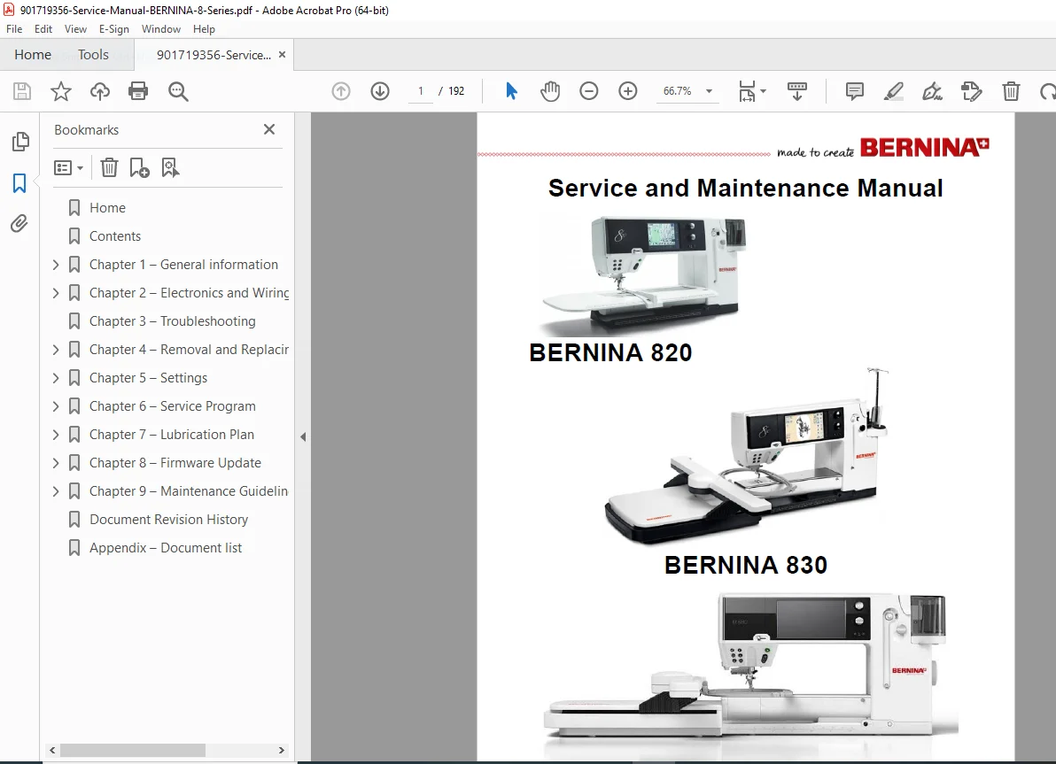
Professional BERNINA 8 Series Service and Maintenance Manual
This comprehensive BERNINA 8 Series service manual provides complete factory repair, maintenance, adjustment, and troubleshooting instructions for BERNINA’s advanced computerized sewing machines. This BERNINA sewing machine repair guide is essential for authorized BERNINA technicians, qualified service personnel, and dealers maintaining these sophisticated sewing and embroidery systems.
Models Covered
This BERNINA 820 830 880 service manual covers the following BERNINA 8 Series sewing machines:
- BERNINA 820 – Computerized sewing machine with touchscreen
- BERNINA 830 – Computerized sewing and embroidery combination machine
- BERNINA 880 – Advanced sewing and embroidery combination machine
Table of Contents
Chapter 1: General Information
- Safety regulations and warnings
- Dangerous voltage level precautions
- ESD (Electrostatic Discharge) protection protocols
- ESD workstation requirements
- Earthing wristband procedures
- Component handling guidelines
- ESD protective packaging requirements
- Required tools and gauges
- BERNINA special tools and part numbers
- Multi-functional tools
- Torx screwdrivers and adjustment tools
- Distance gauges and measuring instruments
- Commercially available tools list
- Settings and adjustment procedures overview
- Abbreviations and terminology
- Cleaning procedures and recommendations
- Complete technical specifications
- Copyright and service manual usage restrictions
Chapter 2: Electronics and Wiring
PCBA (Printed Circuit Board Assembly) Components
- PCBA-Base general information
- PCBA-Base for BERNINA 880
- PCBA-Base for BERNINA 830
- PCBA-Base for BERNINA 820
- PCBA-CPU-Module (ARM9 processor)
- ARM9 architecture for BERNINA 880
- ARM9 configuration for BERNINA 830
- ARM9 setup for BERNINA 820
- PCBA-Front-Cover boards
- BERNINA 830 front cover electronics
- BERNINA 820 front cover electronics
- PCBA-Power supply board
- PCBA-Threader-Sensor electronics
- PCBA-Threader-Start-Sensor (TSS)
- PCBA-Hook-Sensor (light barriers for hook position)
- PCBA-Console control board
- PCBA-Dual-Feed-Sensor
- PCBA-Upper-Thread-Sensor
- PCBA-Position encoder board
- PCBA-RET (rotary encoder) board
- PCBA-Winder-Sensor bobbin winder electronics
- PCBA-Lower-Thread-Sensor
- PCBA-Accessory-Connection interface
- PCBA-Presser-Foot-Height-Sensor
- Sensor support ABC (Presser Foot Recognition)
- Complete cable harness diagrams
- Block diagram of electronic systems
- Handling of electronic components
- Returning defective components
- Repair procedures for PCBAs
- ESD protection during service
Chapter 3: Troubleshooting
- Systematic troubleshooting procedures
- Symptom-based diagnostic flowcharts
- Electronic fault isolation
- Mechanical problem diagnosis
- Sensor malfunction troubleshooting
Chapter 4: Removal and Replacing Components
Covers and Access Panels
- Service cover removal
- Spool holder and head frame cover
- Front cover disassembly
- Rear cover removal
- Bobbin door access
- Free arm cover removal
- Hook sensor and hook cover
- Free arm cover plate
Electronics and Sensors
- PCBA-front-cover replacement
- Stitch length and width adjusting knobs
- Winder complete with threader start sensor
- Bobbin winder assembly
- LCD screen and touch screen replacement
- PCBA-RET, rubber keypad, and ribbon cable
- PCBA-Base board replacement
- PCBA-CPU-module replacement
- EEPROM (Electrically Erasable Programmable Read-Only Memory)
- Free arm LED sewing light
- PCBA-power including housing
- PCBA-power board standalone
- Head frame LED sewing light
- PCBA-hook-sensor replacement
- Presser foot height sensor
- PCBA-threader board
- PCBA-Console replacement
- Sensor-support-ABC (presser foot sensor)
- PCBA-dual-feed-sensor
- PCBA-Accessory and BSR (BERNINA Stitch Regulator) connection
- Centring plate with embroidery module connection (BERNINA 830)
- Lower thread indicator (PCBA-Lower-Thread-Sensor)
Mechanical Components
- Bobbin carrier replacement
- Hook assembly removal and installation
- Thread cutter mechanism
- Swing bearing replacement
- Thread tension and regulator threader entire unit
- Thread tension unit and regulator threader
- Threader head replacement
- Thread positioner
- Main switch and power connection
- Needle bar support
- Needle bar replacement
- Needle clamp
- Threader mechanism disassembly
- Main motor replacement
- Dual feed assembly
- Dual-feed stepping motor
- Gear console removal
- Disassembly and assembly of gear console
- Thread take-up mechanism
- Stitch length crank shaft
- Base shaft replacement
- Stitch length stepping motor
- Sideways-motion stepping motor
- Presser foot pressure stepping motor
- Stitch width stepping motor
- Presser foot pressure toothed rack bearing
- Base plate removal
Chapter 5: Settings and Adjustments
Basics and General Information
- Belt tension adjustments
- Drive motor belt tension
- Head frame plate positioning
- Y direction rough adjustment
- X direction positioning
Presser Foot Settings
- Darning foot height adjustment
- Presser foot fixation
Needle Settings
- Distance between needle bar and presser foot bar
- Needle distribution adjustment
- Zigzag stitch width limiter
Hook, Needle Drive, and Feed-Dog Synchronization
- Feed-dog lift and advance timing
- Synchronization of base shaft and main shaft
- Bobbin case retainer adjustment
- Loop lift setting
- Needle/hook distance critical adjustment
- Needle penetration in Y direction
- Needle height setting
Feed-Dog Settings
- Main feed-dog position within stitch plate (X direction)
- Dual feed X-direction positioning against main feed-dog
- Main feed balance mechanical basic setting
- Dual feed balance basic mechanical setting
- Main feed-dog height (0.9-1.0mm specification)
- Synchronization of main feed-dog and dual feed
Drive Console and Thread Cutter
- Pinning position of drive console gearwheel and hook locking lever
- Thread cutter basic position
Synchronizing Disc
- Rough setting procedures
- Fine-adjustment procedures
Automatic Threader
- Checking the threader unit
- Threader head height adjustment
- Needle bar clamp adjustment
Basting Device
- Needle bar guide adjustment
- Checking timing of disengagement
Thread Systems
- Thread regulator spring tension
- Upper thread tension adjustment
- Lower thread tension setting
Winder Adjustments
- Bobbin filling level
- Even filling adjustment
- Lower thread indicator position (PCBA-Lower-Thread-Sensor)
Chapter 6: Service Program
Starting Test Program and Menu Navigation
Menu 1: Service Information
- Sewing/embroidery machine basic data
- Software and firmware version data
- Operating time data tracking
- Stitch counter data
- BSR (BERNINA Stitch Regulator) data
- Servicing data and history
- Saving and loading customer data
- Customer data management
- Dealer data information
- Log file access and analysis
Menu 2: Display, Buttons, and Clock
- Touch screen calibration procedures
- LCD display testing
- Blank dark LCD screen test
- Blank white LCD screen test
- RGB (Red, Green, Blue) screen test
- Keyboard lights verification
- Clock and battery testing
- LED brightness adjustment
Menu 3: Sensors (Geographical Location Testing)
- Dual feed sensor testing
- Presser foot height sensor
- Upper thread tension sensor
- Threader preload sensor
- Threader swivel sensor
- Bobbin winder fill level sensor
- Free arm sensor tests
- Console sensor verification
- Knee lifter FHS (Free Hand System) sensor
- Hook position sensor
- Lower sensor testing
- Bobbin door sensor
Menu 4: Signals
- Stitch width and length adjusting knobs
- Keyboard functionality testing
- Start/Stop unit (SSU) slide control
- Foot control unit testing
- PS2 interface verification
- Upper thread detection
- BERNINA Stitch Regulator (BSR) foot
- PCBA-Position testing
- Mechanical fine-adjustment of synchronization disc
- Speaker testing
- USB Host verification
- Basting solenoid testing
- Presser foot recognition
- BSR foot interface
Menu 5: Motors (Geographical Location)
- Stitch width stepping motor testing
- Presser foot pressure stepping motor
- Upper thread tension stepping motor
- Dual feed stepping motor
- Pinning position of all stepping motors
- Bobbin winder motor testing
- Stitch length stepping motor
- Console stepping motor
- Sideways stepping motor
Menu 6: Adjustments
- Test-sewing in sewing mode
- Electronic balance calibration
- Basic setting procedures
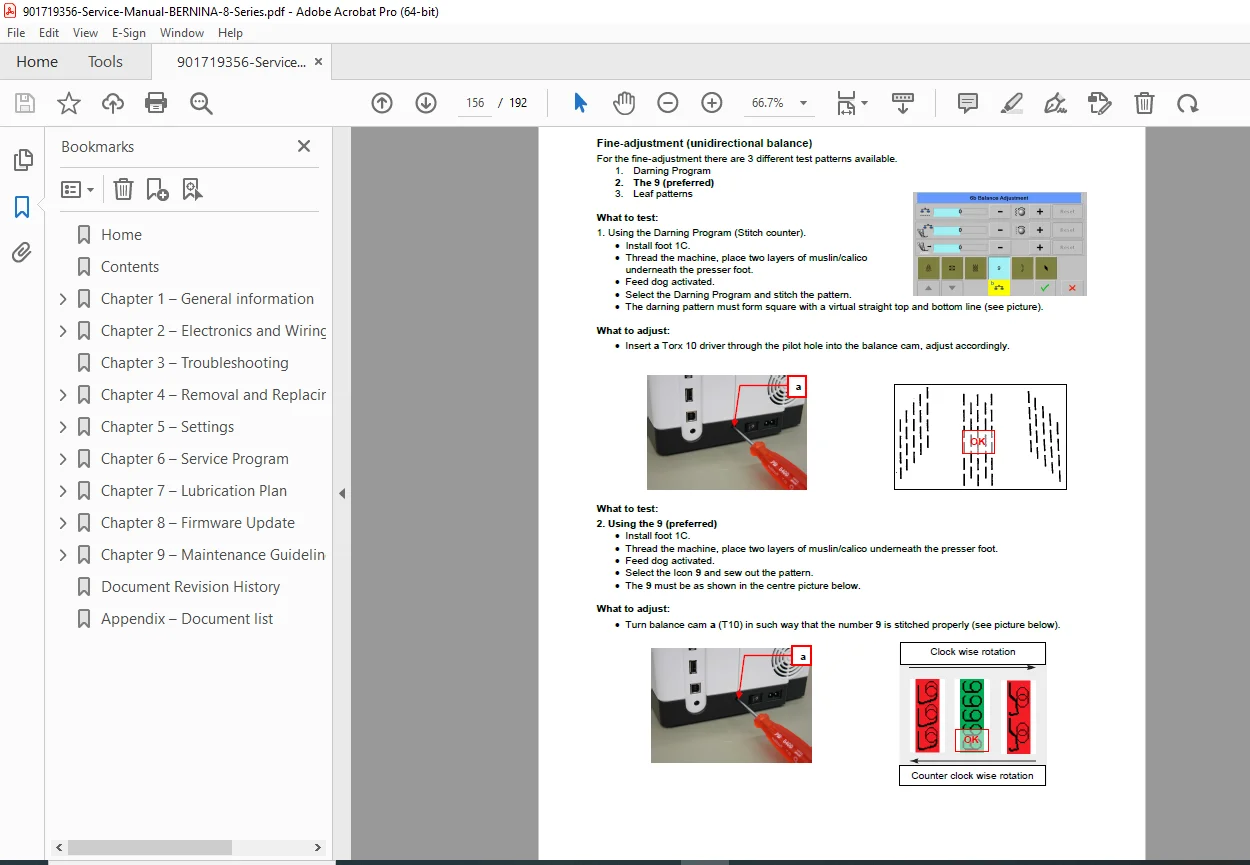
- Fine-adjustment (unidirectional balance)
- Fine-adjustment (multidirectional balance)
- BDF (Dual Feed) balance
- Buttonhole calibration
- Thread cutter process calibration
- Presser foot height and pressure
- Reset upper thread tension
- Resetting to factory settings (Reset all)
- Calibrating automatic thread tension regulator arm
- Automatic threading process
- Upper thread tension adjustment
- Hook swing out device
- Start/stop unit calibration
- Standard SSU sewing speed
- Sew testing with BSR
- Console motor calibration
Menu 7: Embroidery
- Embroidery-specific testing procedures
Menu 11: Check-Out
- Complete system verification tests
- Final checkout procedures
Chapter 7: Lubrication Plan
- Complete lubrication point identification
- Recommended lubricants
- Lubrication intervals
- Critical lubrication areas
- Lubrication procedures
Chapter 8: Firmware Update
- Update procedure step-by-step
- Alternative update entry method
- Firmware version compatibility
- Update troubleshooting
Chapter 9: Maintenance Guidelines
- Purpose of maintenance guidelines
- Stitch and hour counter explanations
- Cleaning message triggers
- Maintenance message triggers
- Stitch counting methodology
- Calculation tables
- Implementation of maintenance intervals
- Maintenance interval schedules
- Cleaning and service stitch reset
- Wear-and-tear parts definition
- Non-hour-related parts
- Operating-time related parts
- Maintenance checklist
- Pre-maintenance measures
- Post-service measures
- Functional check procedures
- Complete BERNINA 8 Series maintenance checklist
- Embroidery module maintenance
Key Features
✓ Complete ARM9 CPU diagnostics and PCBA board troubleshooting
✓ Step-by-step adjustment procedures with precise measurements
✓ Service program access with all menu functions documented
✓ Stepping motor calibration for all five motor systems
✓ Automatic threader repair and height adjustment procedures
✓ Hook timing and synchronization critical adjustments
✓ Dual feed alignment and balance calibration
✓ Touch screen calibration and LCD testing
✓ Firmware update procedures with troubleshooting
✓ Electronic balance calibration (unidirectional and multidirectional)
✓ Complete lubrication plan with diagrams
✓ ESD protection protocols for electronic service
✓ Illustrated parts breakdown with BERNINA part numbers
✓ BSR (BERNINA Stitch Regulator) interface diagnostics
Applications
This BERNINA computerized sewing machine service manual is used by authorized technicians servicing machines in:
- Authorized BERNINA dealerships
- Sewing machine repair shops
- Home sewing businesses
- Quilting studios
- Embroidery businesses
- Textile education facilities
- Industrial sewing operations
- Bridal and alteration shops
Technical Specifications Included
- ARM9 microprocessor architecture
- PCBA board layouts and connections
- Stepping motor specifications (5 motors)
- Touch screen calibration parameters
- Feed-dog height specifications (0.9-1.0mm)
- Hook timing measurements
- Needle height and positioning tolerances
- Thread tension ranges
- LCD display specifications (RGB testing)
- Power supply voltage requirements
- Sensor threshold values
- Firmware version compatibility
- Embroidery module interface specifications
Required Tools and Equipment
The manual specifies BERNINA special tools with part numbers:
- Multi-functional tool (032610.50.00)
- Torx screwdrivers various sizes
- Mounting bracket for service (032763.70.00)
- Distance gauges for threader and needle bar
- Adjusting needles and special gauges
- ESD-compliant workstation equipment
- Earthing wristbands with 1M ohm resistance
- Multimeter and vernier caliper
- Angular Allen and Torx keys
Safety and Compliance
Published by BERNINA International AG with comprehensive ESD protection requirements, dangerous voltage warnings, and authorized dealer restrictions. Manual available only to authorized BERNINA service personnel through BERNINA Infogate Contains critical safety warnings for high-voltage components including CFL backlighting and power supply boards.
File Details
Manual Name: BERNINA 8 Series Service and Maintenance Manual
Models Covered: BERNINA 820, BERNINA 830, BERNINA 880
Publication Date: September 27, 2013
Manual PDF Quality: Excellent – factory original PDF with clear diagrams and text
Number of Pages: 192 pages
Language: English
Format: A4 size pages