Bio-Rad VARIANT II Turbo Service Manual PDF DOWNLOAD
Original price was: $95.00.$28.95Current price is: $28.95.
Supplemental Bio-Rad VARIANT II Turbo service manual PDF for hemoglobin testing systems, detailing specifications, installation, service software, TURBO procedures, replacements, maintenance, troubleshooting with error codes and flowcharts, and appendices on fluidics, mechanics, and electronics. Includes Bio-Rad VARIANT II Turbo installation procedures, VARIANT II Turbo error codes troubleshooting, Bio-Rad VCS VSS service software guide, VARIANT II Turbo chromatography review, and spare parts lists. 148 pages with diagrams and safety guidelines for technicians.
Description
Bio-Rad VARIANT II Turbo Service Manual PDF DOWNLOAD
Description
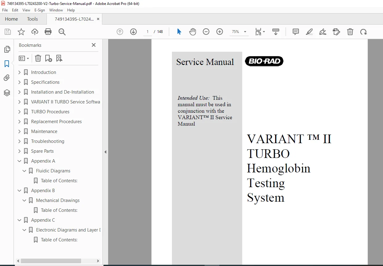
This Bio-Rad VARIANT II Turbo service manual PDF (L70243200, January 2004) serves as a crucial supplement to the main VARIANT II Service Manual, providing specialized guidance for the VARIANT II TURBO Hemoglobin Testing System. It covers system modifications, safety precautions for electrical, mechanical, and biohazard risks, detailed specifications for sampling and chromatographic stations, installation/de-installation steps including Bio-Rad VARIANT II Turbo installation procedures with unpacking, setup, and computer requirements. The manual includes dedicated sections on VARIANT II TURBO service software for VCS and VSS, with manual screens, sensor status details, and adjustments. TURBO procedures outline column heater tweaks, valve replacements, and VSS operations, while replacement guides detail column heater blocks and upgraded tube hold-down sensors with wiring upgrades.
Troubleshooting emphasizes chromatography review, variant hemoglobin patterns, retention times with flowcharts, area counts, VARIANT II Turbo error codes troubleshooting for VCS/VSS/general issues, self-diagnostics sequences, timing charts, and detector noise tests with acceptable/failure criteria and stabilization tips. Maintenance covers materials, VCS/VSS routines, performance verification, and checklists. Appendices provide fluidic diagrams for VCS/VSS tubing, mechanical drawings like column cartridge holders and sampling heads, and electronic diagrams with PCB layer details for connections and drivers.
The manual’s organization includes:
- Table of Contents (Neatly categorized with page numbers):
| Section | Title | Page |
|---|---|---|
| 1 | Introduction | 1-1 |
| 1.1 | Overview | 1-1 |
| 1.2 | System Modifications | 1-2 |
| 1.3 | Safety Precautions | 1-3 |
| 1.3.1 | Electrical | 1-3 |
| 1.3.2 | Mechanical | 1-3 |
| 1.3.3 | Biohazardous | 1-3 |
| 1.3.4 | Safety Procedures | 1-4 |
| 2 | Specifications | 2-1 |
| 2.1 | Sampling Station Physical and Electrical Specifications | 2-1 |
| 2.2 | Sampling Station Component Specifications | 2-1 |
| 2.2.1 | Regulatory Compliance | 2-5 |
| 2.3 | Chromatographic Station Physical and Electrical Specifications | 2-6 |
| 2.4 | Chromatographic Station Component Specifications | 2-6 |
| 2.4.1 | Regulatory Compliance | 2-11 |
| 2.5 | Minimum Computer Specifications | 2-12 |
| 3 | Installation and De-Installation | 3-1 |
| 3.1 | Installation Requirements | 3-1 |
| 3.2 | Unpacking and Inspection | 3-1 |
| 3.3 | VARIANT II TURBO System Setup | 3-3 |
| 3.4 | De-Installation | 3-12 |
| 4 | VARIANT II TURBO Service Software | 4-1 |
| 4.1 | Introduction | 4-1 |
| 4.2 | VCS Service Software | 4-2 |
| 4.3 | VSS Service Software | 4-2 |
| 4.3.1 | Manual Screen | 4-2 |
| 4.3.2 | Sensor Status | 4-3 |
| 4.3.2.1 | Z-Low pos | 4-4 |
| 4.3.2.2 | Status Screen Details | 4-4 |
| 5 | TURBO Procedures | 5-1 |
| 5.1 | VCS Procedures | 5-1 |
| 5.1.1 | Column Heater Adjustment | 5-1 |
| 5.1.2 | 6 and 7 Port Valve Rotor Seal and Stator Replacements | 5-2 |
| 5.2 | VSS Procedures | 5-3 |
| 6 | Replacement Procedures | 6-1 |
| 6.1 | VCS Replacements | 6-1 |
| 6.1.1 | Column Heater Block Replacement | 6-1 |
| 6.2 | VSS Replacements | 6-2 |
| 6.2.1 | Upgraded Tube Hold Down Sensor and Wiring | 6-2 |
| 7 | Maintenance | 7-1 |
| 7.1 | Materials | 7-1 |
| 7.2 | VCS | 7-2 |
| 7.3 | VSS | 7-5 |
| 7.4 | Performance Verification | 7-8 |
| 7.5 | VARIANT II TURBO Maintenance Checklist | 7-8 |
| 8 | Troubleshooting | 8-1 |
| 8.1 | Chromatography Review | 8-1 |
| 8.2 | Variant Hemoglobin Chromatography | 8-3 |
| 8.3 | Retention Times | 8-9 |
| 8.4 | Area Counts | 8-13 |
| 8.5 | Error Codes | 8-15 |
| 8.5.1 | VCS Error Codes | 8-15 |
| 8.5.2 | VSS Error Codes | 8-18 |
| 8.5.3 | General Error Codes | 8-21 |
| 8.6 | Self Diagnostics | 8-22 |
| 8.6.1 | VCST Self Diagnostic Sequence and Flow Chart | 8-22 |
| 8.6.2 | VSST Self Diagnostics Sequence and Flow Chart | 8-24 |
| 8.7 | Timing Chart | 8-27 |
| 8.8 | Detector Troubleshooting | 8-28 |
| 8.8.1 | Detector Noise Test | 8-30 |
| 8.8.1.1 | Acceptable Noise Tests | 8-33 |
| 8.8.1.2 | Failed Noise Test | 8-35 |
| 8.8.1.3 | Lamp Stabilization | 8-38 |
| 9 | Spare Parts | 9-1 |
| 9.1 | TURBO Upgrade Parts | 9-1 |
| 9.2 | Reliability Parts | 9-4 |
| Appendix A | Fluidic Diagrams | A-1 |
| Appendix B | Mechanical Drawings | B-1 |
| Appendix C | Electronic Diagrams and Layer Drawings | C-1 |
List of Figures (Excerpted and categorized; full list spans multiple pages):
- Section 1: Figure 1-1 VARIANT II TURBO Hemoglobin Testing System (1-1)
- Section 3: Figure 3-1 Unpacking the VSS (3-2), Figure 3-2 Unpacking the VCS (3-2), Figure 3-3 HP Compaq D530 Series Computer (3-4), Figure 3-4 Waste Tank Level Sensor (3-4), Figure 3-5 Cartridge Holder (3-6), Figure 3-6 Pump Settings (3-8), Figure 3-7 Configuration Screen (3-10)
- Section 4: Figure 4-1 New VSS Manual Screen (4-2), Figure 4-2 Warning Message for VARIANT II (4-3), Figure 4-3 Z-Low Position in Sensor Status Screen (4-3), Figure 4-4 Sensor Status Screen for VARIANT II (4-4), Figure 4-5 Sensor Status Details (4-5)
- Section 5: Figure 5-1 Temperature Probe in Column Heater (5-1), Figure 5-2 Temperature Probe with Door Closed (5-1), Figure 5-3 6 Port Valve Connections (5-2), Figure 5-4 7 Port Valve Connections (5-2)
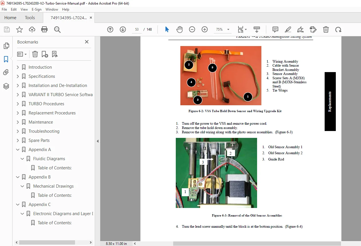
- Section 6: Figure 6-1 VSS Tube Hold Down Assembly (6-2), Figure 6-2 VSS Tube Hold Down Assembly Sensor and Wiring Upgrade Kit (6-3), Figure 6-3 Removal of the Old Sensor Assemblies (6-3), Figure 6-4 Turning the Lead Screw (6-4), Figure 6-5 Installing the Sensor Bracket (6-4), Figure 6-6 Securing the New Sensor Assembly (6-5), Figure 6-7 Inserting the Cable at the Connector (6-5), Figure 6-8 Securing the Cable Bracket (6-6), Figure 6-9 Checking the Cable (6-6), Figure 6-10 Installing the New Wiring Assembly (6-7), Figure 6-11 Upgraded Tube Hold Down Assembly (6-7)
- Section 8: Figure 8-1 Acceptable A1c Chromatogram (8-2), Figure 8-2 Heterozygous Hemoglobin E (8-4), Figure 8-3 Heterozygous Hemoglobin D (8-5), Figure 8-4 Heterozygous Hemoglobin S (8-6), Figure 8-5 Heterozygous Hemoglobin C (8-7), Figure 8-6 Hemoglobin C Carryover (8-8), Figure 8-7 Misidentified A1c Peak (8-9), Figure 8-8 Early Retention Time Flow Chart (8-10), Figure 8-9 Late A1c Retention Time Flow Chart (8-11), Figure 8-10 Late Ao Retention Time Flow Chart (8-12), Figure 8-11 VCST Self Diagnostic Flow Chart (8-23), Figure 8-12 VSST Self Diagnostic Flow Chart (8-26), Figure 8-13 TURBO Timing Chart (8-27), Figure 8-14 Detector Troubleshooting Flow Chart (8-29), Figure 8-15 RAW Data.exe Screen (8-31), Figure 8-16 Noise Test Spreadsheet (8-32), Figure 8-17 Ideal Noise Test Result (8-33), Figure 8-18 Acceptable Noise Test (8-34), Figure 8-19 Passed with Slight Fuzz (8-34), Figure 8-20 Failed with High Drift (8-36), Figure 8-21 Noise Test Flow Chart (8-37), Figure 8-22 Lamp Stability Drift Comparison (8-38)
No alphabetical index is present. Ideal for Bio-Rad VCS VSS service software guide tasks, VARIANT II Turbo chromatography review, and lab system upkeep with genuine parts. Specifications may change; verify with actual equipment.
File Details
- Manual Name: VARIANT™ II TURBO Hemoglobin Testing System Service Manual
- Models Covered: VARIANT II TURBO
- Year: 2004
- Manual PDF Quality: High quality with clear text, diagrams, and illustrations
- No. of Pages: 148