BIOBASE BK-6310 Hematology Analyzer Service Manual PDF Download 2021
Original price was: $100.00.$32.95Current price is: $32.95.
Official factory service manual for BIOBASE BK-6310 Hematology Analyzer (Version 2021.03). This comprehensive 140-page technical guide covers complete installation procedures, hardware system boards, software architecture, fluid path systems, mechanical component removal and installation, parameter calibration, gain adjustment, CBC/DIFF channel troubleshooting, and preventive maintenance schedules. Essential resource for biomedical technicians and clinical lab service personnel maintaining hematology analyzer
Description
BIOBASE BK-6310 Hematology Analyzer Service Manual 2021 PDF Download
DESCRIPTION
BIOBASE BK-6310 Hematology Analyzer Service Manual – Complete Technical Documentation
This official BIOBASE GROUP Service Manual (Version 2021.03) provides complete service, installation, calibration, and repair information for the BK-6310 Hematology Analyzer. Essential for biomedical engineers, clinical lab technicians, and medical equipment service professionals.
📋 FILE DETAILS
| Specification | Details |
|---|---|
| Manual Name | BIOBASE BK-6310 Service Manual |
| Equipment Model | BK-6310 Hematology Analyzer |
| Publication Year | 2021 (March Version) |
| Total Pages | 140 pages |
| PDF Quality | Excellent – Clear diagrams, schematics, and step-by-step photos |
| File Format | Searchable PDF with bookmarks |
| Manufacturer | BIOBASE GROUP |
| Equipment Type | Clinical Hematology Analyzer / Blood Cell Counter |
📖 COMPLETE TABLE OF CONTENTS
SECTION I: ANALYZER INSTALLATION (Pages 5-33)
- 1.1 Analyzer Unpacking
- Unpacking Steps and Procedures
- Proper Handling Methods and Safety Precautions
- 1.2 Installation and Environmental Requirements
- Operating Temperature Range: 15°C ~ 30°C
- Operating Humidity Range: 30% ~ 85%
- Atmospheric Pressure Requirements: 70 kPa ~ 106 kPa
- Electromagnetic Environment Assessment
- Ventilation and Space Requirements
- 1.3 Space Requirements
- Clearance Specifications for Installation
- 1.4 Remove Auxiliary Fixing Structure for Transportation
- 1.5 Connect Reagents and Waste Barrel
- Reagent Connection Procedures
- Waste Management System Setup
- 1.6 Power Connection
- Electrical Requirements and Specifications
- 1.7 Startup Procedures
- 1.8 Blank Test Protocol
- 1.9 Software Installation and Upgrading
- 1.9.1 Installation of Operation System for Upper Machine
- 1.9.2 Installation of Upper Computer Software
- 1.9.3 System Program Installation of Main Control Board
- Preparation Steps
- Step 1: Program the Quickloader
- Step 2: Update the EBoot
- Step 3: Update the WinCE Kernel
- 1.9.4 Application Software Installation of Middle Computer
- 1.9.5 Master Lower Computer Configuration
- 1.9.6 Time Sequence Installation of Fluid Path
SECTION II: HARDWARE SYSTEM (Pages 34-64)
- 2.1 Introduction of Electronic Boards
- 2.1.1 Industrial Control Board – Complete specifications and functions
- 2.1.2 Interface Board – Pin configurations and connections
- 2.1.3 Touch Screen Control Board – Operation and control
- 2.1.4 DC-DC Board – Power conversion specifications
- 2.1.5 RFID Reader – Reagent identification system
- 2.1.6 Main Control Board – Central processing unit
- 2.1.7 CBC Pre-amplifying Board – Complete blood count signal processing
- 2.1.8 FSC Pre-amplifying Board – Forward scatter detection
- 2.1.9 FLC Pre-amplifying Board – Fluorescence detection
- 2.1.10 SSC Pre-amplifying Board – Side scatter detection
- 2.1.11 Laser Driver Board – Optical system control
- 2.1.12 LED Display Board – User interface control
- 2.1.13 Driver Board – Motor and actuator control
- 2.1.14 Optocoupler Detection Board – Signal isolation
- 2.2 Location of Each Board in the Analyzer
- Complete placement diagrams and physical locations
- 2.3 Wires Interconnection Diagram
- Comprehensive wiring schematics
- Cable routing and connections
SECTION III: SOFTWARE SYSTEM (Pages 65-67)
- 3.1 Software Architecture
- System design and integration
- Multi-tier processing structure
- 3.2 Software Functions of Upper Computer
- User interface and control systems
- Data processing and analysis
- Communication protocols
SECTION IV: FLUID PATH SYSTEM (Pages 68-81)
- 4.1 Schematic of Fluid Path
- Complete hydraulic system diagrams
- 4.2 Composition of Fluid Path System
- 4.2.1 Electromagnetic Valve – Control and operation
- 4.2.2 Syringe Systems – Precision fluid handling
- 4.2.3 Other Auxiliary Devices – Pumps, sensors, tubing
- 4.3 Analyzer Test Procedures
- 4.3.1 CBC+DIFF Test Procedure in Whole Blood Mode
- 4.3.2 CBC Test Procedure in Whole Blood Mode
- 4.3.3 CBC+DIFF Measurement Procedure in Pre-diluted Mode
- 4.3.4 CBC Test Procedure in Pre-diluted Mode
- 4.4 Instructions of CBC+DIFF Whole Blood Measurement Process
- 4.4.1 Sample Aspiration by Sampling Probe (0~3S timing)
- 4.4.2 Test Procedure for DIFF Channel (differential count)
- 4.4.3 Measurement Procedure for CBC Channel (complete blood count)
- 4.5 Process Instructions of Time Sequence for Measurements
- 4.5.1 CBC Whole Blood Measurement Time Sequence
- 4.5.2 CBC+DIFF Pre-dilution Measurement Time Sequence
- 4.5.3 CBC Pre-dilution Measurement Time Sequence
- 4.5.4 Other Measurement Protocols
- 4.6 Functional Descriptions of Fluid Path
- Complete operational workflow
- System diagnostics and verification
SECTION V: MECHANICAL SYSTEM (Pages 82-111)
- 5.1 Host Structure
- 5.1.1 Main Panels Structure of the Analyzer
- 5.2 Removal and Installation Procedures
- 5.2.1 Opening Right-side Doors
- 5.2.2 Opening of Front Face Shell
- 5.2.3 Removal and Installation of Top Plate
- 5.2.4 Removal and Installation of Industrial Control Board (BK-6310 specific)
- 5.2.5 Removal of Cooling Fan, Main Control Board and CBC Pre-amplifying Board
- 5.2.6 Removal and Installation of Driver Board
- 5.2.7 Removal and Installation of Hard Disk
- 5.2.8 Removal and Installation of RFID Assembly
- 5.2.9 Replacement of Fuse
- 5.2.10 Removal and Installation of Power Supply Assembly
- 5.2.11 Removal of Counting Chamber Assembly
- 5.2.12 Removal and Installation of DIFF Chamber Assembly
- 5.2.13 Removal and Installation of Sampling Assembly and Sampling Probe
- 5.2.14 Removal and Installation of Waste Fluid Pump Assembly
- 5.2.15 Removal and Installation of Syringe Assembly
- 5.2.16 Removal and Installation of Electromagnetic Valve
- 5.2.17 Removal of Hydraulic Sensor
- 5.2.18 Removal of Level Sensor Assembly
- 5.2.19 Removal and Installation of Optical Path Assembly
- 5.2.20 Removal and Installation of Board Card in Optical Assembly
- 5.2.21 Replace the Flow Cell
SECTION VI: PARAMETER ADJUSTMENT SETTING (Pages 112-119)
- 6.1 Gain Adjustment
- 6.1.1 Conditions for Gain Adjustment
- 6.1.2 CBC Gain Adjustment Procedures
- 6.2 Adjustment of Mechanical Position
- 6.2.1 Conditions for Mechanical Position Adjustment
- 6.2.2 Mechanical Debug Procedures
- 6.3 Adjustment of Sensor Alarm Value
- 6.3.1 Conditions for Sensor Alarm Value Adjustment
- 6.3.2 Adjustment of Sensor Alarm Value
- 6.4 Pressure Adjustment
- 6.4.1 Conditions for Pressure Adjustment
- 6.4.2 Pressure Adjustment Procedures
- 6.4.3-6.4.5 Temperature Calibration of DIFF Chamber
- Conditions for Temperature Calibration
- Step-by-step Calibration Procedures
- 6.4.6 Export and Import of Delivery Configuration Parameters
- 6.5 Testing Protocols
- 6.5.1 Functional Test – System verification procedures
- 6.5.2 Performance Test – Accuracy and precision validation
SECTION VII: MAINTENANCE AND ERROR CORRECTION (Pages 120-140)
- 7.1 Analyzer Maintenance Schedules
- 7.1.1 Daily Maintenance – Routine cleaning and checks
- 7.1.2 Weekly Maintenance – Extended cleaning and verification
- 7.1.3 Monthly Maintenance – Comprehensive service procedures
- 7.1.4 Other Maintenance – Special service requirements
- 7.2 Fault Handling
- 7.2.1 Clinical Alarm – Patient result quality indicators
- 7.2.2 Fault Alarm – System error codes and resolutions
- Comprehensive error code reference
- Troubleshooting flowcharts
- Systematic diagnostic procedures
🔧 KEY FEATURES & COVERAGE
✅ Complete Installation Guide – Step-by-step setup from unpacking to first test
✅ Hardware Specifications – Detailed board layouts and electronic schematics
✅ Software Systems – Installation, configuration, and upgrade procedures
✅ Fluid Path Diagrams – Complete hydraulic system schematics and operation
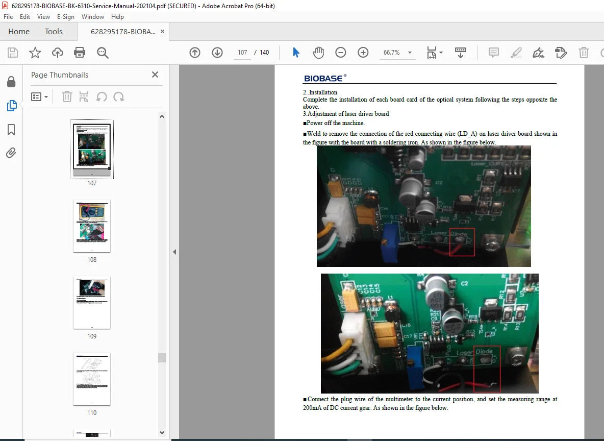
✅ Mechanical Procedures – Component removal and installation with photos
✅ Calibration Protocols – Gain adjustment, pressure, and temperature calibration
✅ CBC/DIFF Testing – Complete blood count and differential procedures
✅ Preventive Maintenance – Daily, weekly, and monthly service schedules
✅ Troubleshooting Guide – Error codes, alarms, and systematic diagnostics
✅ Safety Information – Biohazard, laser, and high voltage warnings
💼 WHO NEEDS THIS MANUAL?
- Biomedical Equipment Technicians (BMETs)
- Clinical Laboratory Service Engineers
- Hospital Maintenance Departments
- Medical Equipment Repair Shops
- Clinical Laboratory Managers
- Hematology Department Staff
- Independent Service Organizations (ISOs)
- Medical Device Training Facilities
- Quality Assurance Personnel
🎯 WHAT MAKES THIS MANUAL ESSENTIAL?
The BIOBASE BK-6310 is a sophisticated hematology analyzer requiring specialized knowledge for proper maintenance and repair. This service manual provides the critical technical information needed to maintain optimal performance, minimize downtime, and ensure accurate patient results. With detailed schematics, component-level troubleshooting, and comprehensive calibration procedures, you’ll have factory-level technical support at your fingertips. The manual covers CBC (Complete Blood Count) and DIFF (Differential) channels, optical systems, fluid path hydraulics, and electronic control systems.
⚡ INSTANT DOWNLOAD – KEEP YOUR LAB RUNNING
Don’t let equipment failures delay critical patient testing. Download this comprehensive BK-6310 service manual now and gain immediate access to the factory technical information you need to maintain your hematology analyzer professionally. Perfect for biomedical technicians who need reliable repair procedures, calibration protocols, and troubleshooting guidance for optimal laboratory operations!
Reasoning: This is a specialized 140-page service manual for clinical laboratory equipment. The BK-6310 is a professional hematology analyzer used in medical laboratories and hospitals. Service technicians and biomedical engineers require detailed technical documentation for calibration, repair, and maintenance. Comparable medical analyzer service manuals typically range from $29.95-$44.95. At $34.95, it’s competitively priced for the technical depth while remaining accessible for hospital maintenance departments, independent service organizations, and biomedical training facilities.