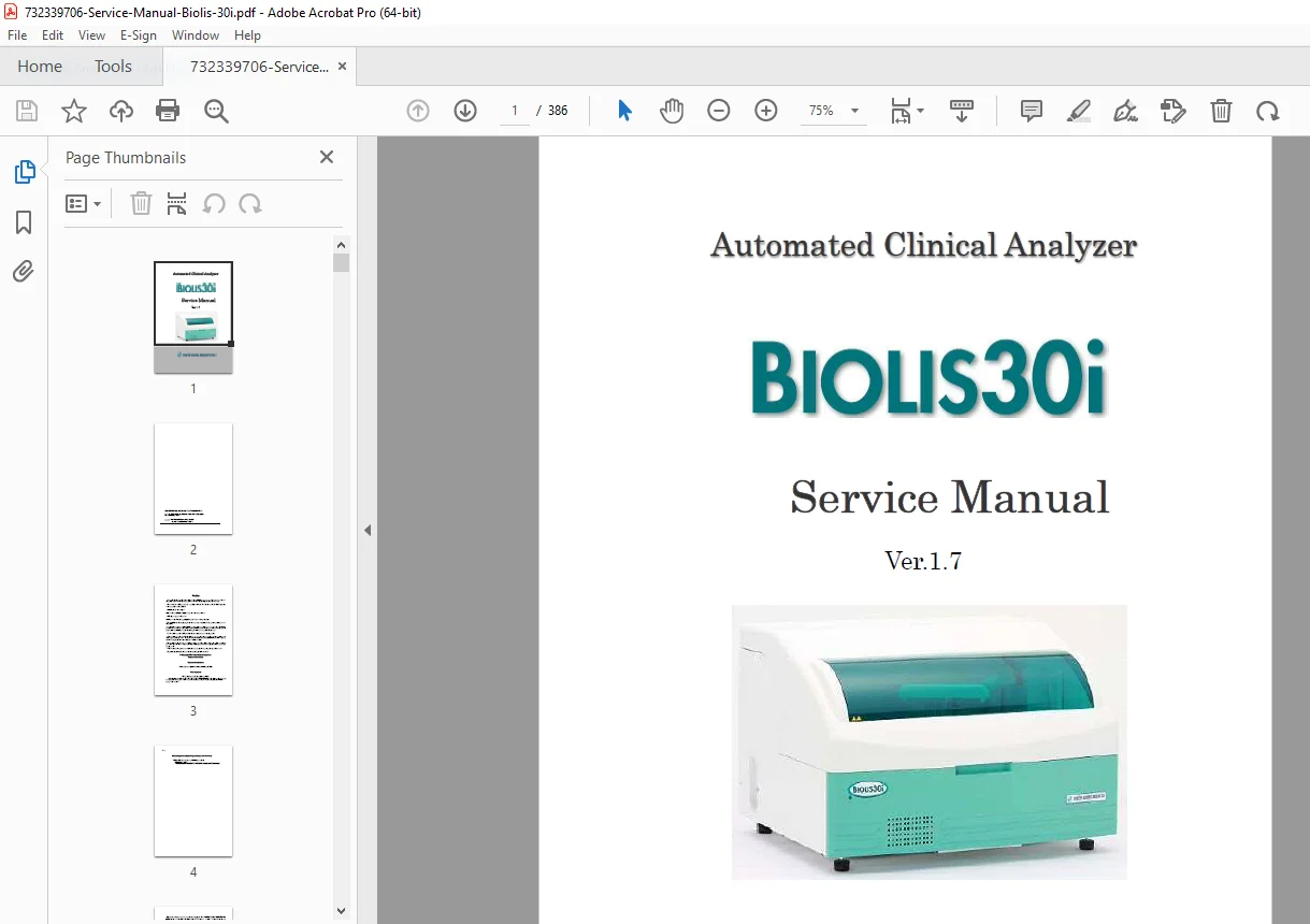
Biolis 30i Service Manual PDF DOWNLOAD
Original price was: $95.00.$29.95Current price is: $29.95.
Comprehensive Biolis 30i service manual PDF for the Tokyo Boeki Medisys automated clinical analyzer, covering specifications, unit explanations, power supply, FPGA version update procedures, liquid level sensor adjustments, error codes troubleshooting, clot detection log analysis, backup tools, and maintenance. Includes Biolis 30i FPGA version update procedure details, Biolis 30i liquid level sensor adjustment guides, and Biolis 30i clot detection log analysis methods with diagrams and tables. 386 pages for lab technicians.
Description
Biolis 30i Service Manual PDF DOWNLOAD
Description
This official Biolis 30i service manual PDF (Ver. 1.7) from Tokyo Boeki Medisys Inc. is a detailed resource for servicing the BIOLIS30i automated clinical analyzer, emphasizing safety cautions, warranty, and operational principles. It provides in-depth coverage of system specifications, structural overviews, functional explanations, unit disassembly, control PCBs, FPGA version update procedures, liquid level sensor adjustments, error codes troubleshooting, clot detection log analysis, tools for backup and restoration, and various settings like IP address changes and barcode reader adjustments. The manual supports Biolis 30i error codes troubleshooting with PCB-specific diagnostics, Biolis 30i liquid level sensor adjustment for noise level confirmation, and Biolis 30i clot detection log analysis via specialized viewers and parameters.
Key sections include warnings on biohazards, electrical safety, and proper disinfection, ensuring compliance with EC standards. The preface outlines usage environments, installation, and storage requirements. For advanced maintenance, chapters detail Biolis 30i FPGA version update procedure with file writing instructions, Biolis 30i liquid level sensor adjustment using noise level screens, and Biolis 30i clot detection log analysis with graph interpretations and parameter defaults.
The manual is structured as follows:
- Table of Contents (Neatly categorized from pages C-1 to C-9):
| Section | Title | Page |
|---|---|---|
| – | Caution | – |
| – | EC Declaration of Conformity | – |
| – | Software license agreement | – |
| – | A rule related to the service engineer training and qualification | – |
| Preface | Introduction | 0-2 |
| Preface | 1. Expression of Warning and Notice | 0-3 |
| Preface | 2. Safety Caution ・Caution in Operation | 0-7 |
| Preface | 3. Warranty | 0-10 |
| Preface | 4. Storage and Transportation Requirements | 0-12 |
| Preface | 5. Usage environment | 0-12 |
| Preface | 6. Installation and Servicing | 0-13 |
| Preface | 7. Cleaning and disinfection procedure | 0-13 |
| Preface | 8. Position of the nameplate | 0-13 |
| Chapter 1 | Specifications and structure of the System | 1-3 |
| 1.1 | General Specifications | 1-3 |
| 1.2 | Structure of the System | 1-6 |
| 1.2.1 | Over All Structure | 1-6 |
| 1.2.2 | Plan of the System Section | 1-7 |
| 1.2.3 | Rear view | 1-7 |
| 1.2.4 | Left Side Elevation of the System | 1-8 |
| 1.2.5 | Right Side Elevation of the System | 1-9 |
| 1.2.6 | Reservoirs | 1-10 |
| 1.2.7 | Personal computer | 1-12 |
| 1.3 | Panel composition | 1-13 |
| Chapter 2 | Functions and principles | 2-3 |
| 2.1 | System overview | 2-3 |
| 2.2 | Principle of measurement | 2-4 |
| 2.3 | Units and functions | 2-8 |
| Chapter 3 | Explanations about Units | 3-6 |
| 3.1 | Overview | 3-6 |
| 3.2 | Sampling | 3-10 |
| 3.3 | Reagent | 3-33 |
| 3.4 | Reaction | 3-62 |
| 3.5 | Mixing | 3-69 |
| 3.6 | Measurement | 3-81 |
| 3.7 | Reaction cell washing | 3-93 |
| 3.8 | Supply and drain water | 3-124 |
| 3.9 | ISE Unit | 3-128 |
| Chapter 4 | Power supply unit・Control PCB | 4-4 |
| 4.1 | Power supply unit | 4-4 |
| 4.2 | Fuse | 4-7 |
| 4.3 | Control PCBs and errors | 4-8 |
| 4.4 | JID PCB(CAB PCB1) | 4-10 |
| 4.5 | DCHT PCB(CAB PCB2) | 4-14 |
| 4.6 | IODRV PCB(CAB PCB3) | 4-18 |
| 4.7 | CPSIF PCB(CAB PCB4) | 4-21 |
| 4.8 | ACRY PCB(CAB PCB5) | 4-26 |
| 4.9 | GDRV PCB(CAB PCB7,8,9) | 4-28 |
| 4.10 | CLS PCB | 4-30 |
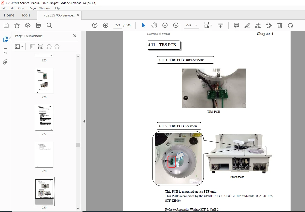
| 4.11 | TRS PCB | 4-33 |
| 4.12 | LVLS PCB (Liquid level sensor PCB) | 4-35 |
| 4.13 | RCT driver PCB(CAB PCB6) | 4-37 |
| Chapter 5 | FPGA version up | 5-3 |
| 5.1 | Instruction of the FPGA | 5-3 |
| 5.2 | Confirmation of the FPGA version | 5-4 |
| 5.3 | FPGA version up procedure | 5-5 |
| Chapter 6 | Confirmation of liquid level signal | 6-3 |
| 6.1 | Confirmation of liquid level signal | 6-3 |
| Chapter 7 | Liquid level sensor error and signal log | 7-3 |
| 7.1 | Liquid level sensor error | 7-3 |
| 7.2 | Signal log of liquid level detection | 7-4 |
| 7.3 | Level Log tool | 7-6 |
| 7.4 | Setting of the liquid level detection and delay | 7-13 |
| Chapter 8 | Clot detection log and parameter value | 8-3 |
| 8.1 | Clot detection log | 8-3 |
| 8.2 | Clot Log Viewer | 8-3 |
| 8.3 | How to confirm the clot sensor movement? | 8-3 |
| 8.4 | Clot sensor movement check | 8-3 |
| 8.5 | Review of the clot sensor parameter | 8-3 |
| 8.6 | Clot sensor setting | 8-3 |
| 8.7 | Clot sensor parameter default value | 8-3 |
| 8.8 | Clot parameter value setting | 8-3 |
| Chapter 9 | Tools | 9-3 |
| 9.1 | Kind of tools | 9-3 |
| 9.2 | List creation for doctor and section name | 9-4 |
| 9.3 | Display of test count | 9-6 |
| 9.4 | Operator level and password setting | 9-7 |
| 9.5 | Volume range setting | 9-9 |
| 9.6 | Error Sounds Setting | 9-10 |
| Chapter 10 | Backup and restoration | 10-3 |
| 10.1 | TOOL FOR DATABASE BACKUP | 10-3 |
| 10.2 | Back up tool(For user screen/ service screen) | 10-4 |
| 10.3 | Database Backup and restoration | 10-8 |
| 10.4 | Location change of storage file | 10-12 |
| 10.5 | Log backup | 10-14 |
| Chapter 11 | [Various change, setting and confirmation] | 11-3 |
| 11.1 | Changing of IP address | 11-3 |
| 11.2 | Barcode reader adjustment | 11-18 |
| 11.3 | Adjustment of the cup sensor | 11-22 |
| 11.4 | Setting the maximum descent position of the sample probe when measuring sample with cup on tube | 11-26 |
General specifications are detailed in tables:
- General Specifications Table 1 (Page 35):
| Item | Contents |
|---|---|
| Method | Discrete, Single line random access, multi-tests analysis |
| Test items on board | 36 items (24 items Option)+ ISE 3 items |
| Throughput | 270 tests/hr. · MAX 450tests/hr. (in case of loading ISE) · 90 test/hr. (HbA1c Item Only) |
| Analysis method | End point method, Rate method ISE |
| Calibration curve | Linear, Factor, Non-linear (Logit-log, Spline, Exponential, Polynomial) |
| Reaction time | About 10 min. (1st react. about 5 min+ 2nd react. about 5 min.) |
| Tray mode | Software tray |
| Tray kind | Patient sample tray : Tray No. 1 – 50 Calibration tray : C1 – C6 QC sample tray : Q1 – Q3 |
| Contents of test | Serum, Plasma, Blood cell, Urine, Dialysate, CSF (ISE not available for CFS and Blood cell) |
| Container | Sample cup, Primary tube (5mL, 7mL, 10mL) |
| Sample – Patient sample | 1 – 30 (Outside) |
| Sample – Standard sample | 1 – 45 |
| Sample – Blank sample | 1 – 45 |
| Sample – ISE standard | For serum sample: 2 For urine sample: 2 For dialysis : 1 |
| Sample – QC sample | ➢ Patient sample tray, Calibration tray (Inside) : 31 – 45 ➢ QC sample tray: 1 – 45 |
| Sample – Washing | 3 |
| Sample – ISE washing | 1 |
| Sample – Dispensation volume | 2.0 – 25µL (0.1µL steps) |
| Sample – Dilution ratio | 0.5,6,10,20,30,40,50,60,70,80,90,100 times (When dilution ratio is set 0.5, the sample volume is used two times. Set the sample volume less than 12.5uL and the total reaction volume less than 400uL.) |
- General Specifications Table 2 (Page 36):
| Item | Contents |
|---|---|
| Reagent – Dispensation volume | R1 140-300 µL (1µL steps) R2 20 -260 µL (1µL steps) |
| Reagent – Number of bottles on board | 36 items R1,R2 :36position 24 items (Option) R1,R2 : 24 position |
| Reagent – Storage | Reagents are cooled at 5 – 15 Celsius degrees. The reagent cooling becomes room temperature minus 13°C when the room temperature is over 25°C |
| Reagent – Bottle volume | 36 item : Single R1:40mL, Double R1: 25mL, R2:13mL (24item:Single R1 60 mL, Double R1:40mL,R2:20mL) |
| Mixing method | 2 rooms air pressure mixing (without a stirrer) |
| Reaction tray – Temperature control | Direct block heating |
| Reaction tray – Reaction temperature | 37±0.1Celsius degrees |
| Reaction tray – Reaction cuvette | Material Plastics Optical path length 8 mm Number of cuvette 60 pieces (semi-disposable) Reaction volume 140 – 400 micro-liter |
| Reaction tray – Optical absorption | Cuvette direct measurement |
| Reaction tray – Wavelengths | Fixed 13wavelengths 340,380,405,450,480,505,546,570,600,660,700,750,800nm |
| Spector photometer – Light detector | Silicon photo-diode |
| Spector photometer – Wavelength accuracy | ±1.5nm |
| Spector photometer – Linearity range | 0 – 2.5 Abs. |
| Spector photometer – Light source | Halogen lamp |
| Calculation between item | Calculation based on user’s formula Correlation factor |
| User interface – Monitor function | Reaction curve monitor Data review Run-monitor |
| User interface – Quality control | Westgard algorithms Within day, day to day |
| User interface – Data storage capacity | Based on the PC specification |
| User interface – System interface | Instrument →PC : LAN(TCP/IP) PC→LIS : LAN (TCP/IP) (HL7 Ver2.5standard) |
| Equipment Class | Class I |
- General Specifications Table 3 (Page 37):
| Item | Contents |
|---|---|
| Over voltage Category | Category II |
| Pollution Degree | Pollution Degree 2 |
| Power supply | AC100V/115V/220V/230 V ±10 % |
| Frequency | 50/60 Hz |
| Electric consumption | 600 VA |
| Grounding | Resistive less than 100 ohm |
| Ambient temperature | 15 – 30 Celsius degrees (During operation Plus-minus 2 Celsius degrees/hour) |
| Ambient humidity | 35 – 80%RH (No condensation) |
| Water consumption (Electric conductivity < 1 µS/cm) | About 3.8L/hour |
| Detergent consumption (Alkaline, Acidic) | About 230mL/hour |
| Dimension (system) | 800 (W) ×670 (D) ×555 (H) mm |
| Weight | Approx. 95kg |
| ISE (Option) – Electrodes | Na, K, Cl and Reference electrode. |
| ISE (Option) – Specimen | Serum, Plasma, Urine and Dialysis ➢ Urine are used as sample, measure with a dedicated Dil solution at 6 times Dil (no automatic Dil Function). |
| ISE (Option) – Sample volume : Measurement | Serum, Plasma and Dialysis 60 micro-liter Diluted urine (Use sextuple diluted sample by urine diluent) 120 micro-liter |
| ISE (Option) – Analysis time | Serum, Plasma and dialysis 37 seconds Diluted urine 45 seconds |
| ISE (Option) – Calibrator | Serum Calibrator A, Calibrator B Urine Calibrator Calibrator 1 for urine, Calibrator 2 for urine Dialysis Dialysis calibrator D |
| ISE (Option) – Sample volume : Calibration | Serum, Plasma and Dialysis 120 micro-liter Diluted urine 240 micro-liter |
| ISE (Option) – For automatic purge | Use Calibrator 1 : 400 µL/time • While Main power supply is ON : Once every 2 hours • While System power supply is ON : Once every 30 min. |
Essential for Tokyo Boeki Medisys Biolis 30i maintenance guide tasks, this PDF includes illustrations, flowcharts, and part lists for accurate repairs. Changes may apply without notice; always verify with the actual device.
File Details
- Manual Name: BIOLIS30i Service Manual
- Models Covered: BIOLIS30i
- Year: 2016
- Manual PDF Quality: High quality with clear text, tables, diagrams, and illustrations
- No. of Pages: 386