BioMérieux BacT/Alert 3D 60 Service Manual Blood Culture System Repair PDF
Original price was: $120.00.$34.95Current price is: $34.95.
Complete BioMérieux factory service manual for BacT/ALERT 3D 60 blood culture system. Professional technical documentation with 332 pages covering installation, diagnostics, troubleshooting, preventive maintenance, and component replacement procedures. Includes detailed electrical schematics, software diagnostics, calibration procedures, and complete parts list. Essential for biomedical technicians and clinical laboratory engineers. Instant PDF download with comprehensive wiring diagrams and exploded views.
Description
BioMérieux BacT/Alert 3D 60 Service Manual Blood Culture System Repair PDF DOWNLOAD
DESCRIPTION
Official BioMérieux BacT/ALERT 3D 60 Service Manual
This comprehensive BioMérieux BacT/ALERT 3D 60 service manual provides complete factory-level technical documentation for biomedical equipment technicians and clinical laboratory engineers servicing the BacT/ALERT 3D 60 automated blood culture system. Essential for hospital clinical engineering departments, independent biomedical service companies, and laboratory equipment maintenance professionals.
FILE DETAILS
- Manual Name: BacT/ALERT 3D 60 Service Manual
- System: BacT/ALERT 3D 60 Automated Blood Culture System
- Manual Part Number: 48001-6 Rev A
- Edition: March 2003
- Pages: 332 pages
- PDF Quality: High-quality professional service manual with clear diagrams, electrical schematics, and exploded assembly views
- File Format: Searchable PDF (Letter size, 8.5″ x 11″)
- Copyright: bioMérieux 2002
COMPLETE MANUAL STRUCTURE
CHAPTER 0: FRONT MATTER
Safety Summary:
- General information to follow
- Electrical warnings (high voltage hazards)
- Electrical grounding requirements
- Fuse replacement warnings
- Hazardous voltages (identification and protection)
- Cleaning agents (approved materials and procedures)
- Health risks (biological safety considerations)
- ESD precautions (electrostatic discharge protection)
- Moving parts safety warnings
- Heating element precautions
Typography and Graphic Conventions:
- Bullets usage
- Text boxes
- Bracketed italics
- Underlined text
- Bracketed text
- Quotation marks
- Italicized text conventions
Appendices Overview:
- Glossary
- Parts list (alphabetical)
- Disinfection procedures
- Error codes
- Diagrams
Lists:
- Complete list of tables
- Complete list of illustrations (over 170 figures)
CHAPTER 1: GENERAL INFORMATION
Introduction:
- System overview
- Manual purpose and scope
- Reference documentation
Reference Data:
- Technical specifications table
- Performance parameters
- Environmental requirements
Equipment Description:
- BacT/ALERT 3D 60 system overview
- Automated blood culture detection
- Incubation and monitoring capabilities
- 60-bottle capacity
- Colorimetric detection technology
Assembly Descriptions:
Electrical Components:
Power Panel Assembly:
- Power distribution system
- Voltage regulation
- Electrical safety features
Transformer Assembly:
- Step-down transformer specifications
- Primary/secondary winding details
- Voltage conversion (115V/230V)
Heater:
- Incubator heating element
- Temperature control system
- Thermal regulation
Blower:
- Air circulation system
- Motor specifications
- Airflow distribution
Step-5 Motor Assembly:
- Agitation motor system
- Stepper motor control
- Mechanical linkage
Fan:
- Cooling system
- Ventilation specifications
Quick Reference Card:
- Front side operational guide
- Rear side technical reference
Communications Ports (Input/Output):
COMM Port:
- Serial communication specifications
- Protocol details
Printer Port:
- Parallel printer interface
- Supported printers
Internal Speaker w/External Speaker Jack:
- Audio alarm system
- External speaker connection
Power Entry Module (PEM) / ON-OFF Switch:
- Main power control
- Fuse locations
- Voltage selection
Modem Port:
- Remote diagnostics capability
- 56K FAX modem specifications (domestic/international)
LIS Port:
- Laboratory Information System interface
- Data exchange protocols
Monitor Port:
- External display connection
- VGA specifications
UPS Port:
- Uninterruptible Power Supply interface
- Battery backup system
UPS Serial Port:
- UPS communication
- Status monitoring
Mouse Port:
- USB mouse connection
Keyboard Port:
- Standard keyboard interface
Barcode Scanner Port:
- Sample identification system
- Scanner connectivity
Electronic Components:
CPU PCBA (Printed Circuit Board Assembly):
- Main processor board
- System control functions
- WinSystems computer integration
ModSig PCBA:
- Signal modulation and processing
- Optical detection control
- LED control (55, 56 indicators)
Quad Serial PCBA:
- Multiple serial port interface
- Communication expansion
Thermistor PCBA (Input/Output):
- Temperature sensing
- Inlet and outlet thermistors
- Temperature monitoring circuits
CompactFlash Memory Disk:
- System software storage
- Data logging
- Removable media
CompactFlash Adapter PCBA:
- Memory card interface
- Data transfer
Step-5 PCBA:
- Stepper motor control board
- Agitation system control
- Motor drive circuits
Incubator Chamber Components:
Rack:
- Bottle holding assembly
- 60-position capacity
- Rack addressing system
Cell:
- Individual bottle positions
- Optical detection chambers
- Temperature zones
Cell Flag:
- Positive detection indicator
- Optical flag mechanism
Cell Indicator Lamp:
- Visual status indicators
- LED array
Input/Output Devices:
Operator Display Monitor:
- Touchscreen interface
- Configuration screens
- Status display
Barcode Scanner:
- Sample identification
- Lot number scanning
- Accession number entry
Keyboard:
- Data entry
- System control
Zip Drive:
- Data backup
- 100MB removable storage
- Archive capability
56K FAX Modem (Domestic):
- Remote support connection
- Data transmission
56K Fax Modem (International):
- Global compatibility
- Multi-voltage support
Uninterruptible Power Supply “UPS”:
Domestic Model (APC Back-UPS 650):
- Battery backup specifications
- Runtime capacity
International Model:
- Multi-voltage support
- Global compatibility
UPS Features:
- On/Off switch
- Computer interface port
- Overload reset switch
- Test/Check battery switch
- 120V backup receptacles
- Accessory surge receptacles
- AC power cord
Operator Display Configuration Screens:
- Instrument Configuration Screen access
- Initial entry procedures
- Configuration screen navigation
- X Box button functions
- Field engineer password activation
- Setup screen parameters
Quick Reference Card:
- Front side: Operational procedures
- Rear side: Technical specifications and troubleshooting
CHAPTER 2: BACKGROUND INFORMATION
Introduction:
- System architecture overview
- Component interaction
- Signal flow diagrams
System Control – ModSig PCBA:
- ModSig PCBA diagram (detailed schematic)
- ModSig block diagram (functional blocks)
- Audio frequency selection (jumper settings JP23-JP26)
- Signal processing circuits
- Optical detection control
- LED driver circuits
- Communication interfaces
Thermistor PCBA (Input/Output):
- Temperature sensor circuitry
- Analog-to-digital conversion
- Calibration procedures
- Inlet/outlet temperature monitoring
3D 60 Power Supply Assembly:
- Power distribution block diagram
- Voltage regulation circuits
- Current distribution
- Protection circuits
DC Power Supply:
- Power supply data table
- Output voltages (+5V, +12V, -12V)
- Load specifications
- Ripple and noise specifications
- Regulation tolerance
CPU PCBA:
- CPU PCBA diagram
- Processor specifications
- Memory architecture
- I/O interfaces
- WinSystems board integration
CompactFlash Adapter PCBA:
- Memory card interface circuitry
- Pin configurations
- Data transfer protocols
Quad Serial Interface PCBA:
- Quad serial interface diagram
- UART specifications
- Serial port configurations
- Communication parameters
Rack Controller PCBA:
- Rack controller diagram
- Rack controller block diagram
- Rack address concept
- Cell addressing scheme
- Optical sensor control
- LED multiplexing
Step-5 PCBA:
- Step-5 PCBA diagram
- Step-5 PCBA block diagram
- Stepper motor driver circuits
- Microstepping control
- Position sensing
- Home position detection
CHAPTER 3: INSTALLATION PROCEDURES
Introduction:
- Installation overview
- Site preparation requirements
BacT/ALERT 3D 60 Installation Procedures:
Verification of Site Requirements:
- Environmental specifications
- Electrical requirements
- Space requirements
- Ventilation needs
Record Line Noise:
- Power quality assessment
- Voltage stability verification
Unpacking:
- Protective packaging removal
- Component identification
- Damage inspection
Repacking:
- 3D 60 instrument repacking sequence (illustrated)
- Web strapping diagrams
- Protective materials replacement
- Shipping preparation
Verification of Contents:
- 3D 60 instrument parts list
- Accessory checklist
- Documentation verification
Set AC Power:
- Facility power rating and conversion chart
- Power Entry Module configuration
- 115 VAC version (USA standard)
- 230 VAC version (European standard)
- Fuse holder removal procedure
- Fuse installation (correct ratings)
- Voltage selection verification
Instrument Placement:
- Setup and connections table
- Countertop/surface mounting
- Clearance requirements
- Ventilation spacing
Instrument UPS:
- UPS connection procedures
- Battery backup configuration
- Power protection setup
Power Up:
- Initial startup sequence
- System initialization
- POST (Power-On Self-Test)
Instrument Configuration:
- Configuration screen access
- Parameter settings
- System options
- LIS integration setup
Temperature:
- Incubator temperature verification
- Warm-up time
- Temperature stability check
Error Check:
- System diagnostics
- Error log review
- Fault resolution
Modem Functional Test:
- Communications panel connection diagram
- Modem configuration & DIP switch settings
- Test call procedures
- Connection verification
Barcode Reader Functional Test:
- Scanner calibration
- Scanner default settings barcode
- Test scanning procedures
UPS Functional Test:
- Battery test
- Automatic transfer test
- Runtime verification
Complete the Installation Checklist:
- Installation checklist form
- Sign-off procedures
- Customer acceptance
Restraint Installation:
- Countertop/surface mounting diagram
- Restraint hardware specifications
- Mounting surface diagram
- Table of equivalent dimensions
- Mounting surface drilling template
- Anchor installation procedures
Software Installation:
- CompactFlash card installation
- Software loading procedures
- Version verification
Switching On:
- Initialization sequence
- System readiness verification
CHAPTER 4: SERVICING
Introduction:
- Service procedures overview
- Safety precautions
- Required qualifications
Specific Tools Required:
- Required tools and equipment table
- Standard tools
- Specialized test equipment
- Measurement instruments
Power Up/Down Procedures:
3D 60 Power Down:
- Safe shutdown sequence
- Data preservation
- Component protection
3D 60 Power Up:
- Startup procedures
- System checks
- Verification steps
MB Conversion Procedure:
- Mycobacteria bottle configuration
- Lock screw removal procedure
- Lock screw installation
- Rack reconfiguration
Data Backup/Restore Procedures:
BacT/ALERT 3D 60 Data Backup:
- Backup management button operation
- Zip disk backup procedure
- Data verification
BacT/ALERT 3D 60 Data Restore:
- Restore procedures
- Data recovery
- System reinitialization
Preventive Maintenance:
- Overview and schedule
- Perform data backup (routine)
- Barcode reader functional test
- Printer maintenance
- Temperature verification procedures
- Disabled cell check
- +5 DC voltage verification (test points)
- UPS test procedures
- “Door Open” test
- Completing the preventive maintenance card
Diagnostics and Troubleshooting:
Symptomatic Errors:
- Symptomatic problems table
- Problem isolation
- Corrective actions
Software Diagnostics:
Button Legend:
- Diagnostic button functions
- Navigation controls
Accessing the Diagnostics Screens:
- Setup screen with field engineer password
- Password activation
- Diagnostic menu access
Diagnostic Screens Overview: (Comprehensive coverage of all diagnostic functions)
Incubator Module Tests:
- 1.1 Inc Module 1/Loopback Test – Communication verification
- 1.2 Inc Module 1/Port Stats Test – Port performance monitoring
- 1.3 Inc Module 1/Message Stats Test – Message traffic analysis
- 1.4 Inc Module 1/Message Log Test – Communication logging
- 1.5 Inc Module 1/Temperature Log Test – Temperature history with:
- Find text string function
- Save output to Zip
- Scroll/anchor buttons
- Slide bar navigation
- 1.6 Inc Module 1/Reading Log Test – Optical reading history
- 1.7 Inc Module 1/Flag Check – Cell detection verification with:
- Cell differences screen
- Calibration screen procedures
- 1.8 Inc Module 1/Heater – Heating system diagnostics
- 1.9 Inc Module 1/LED Check – LED indicator testing with:
- Walking test patterns
- Individual LED verification
Instrument Control Tests:
- 7.1 Instrument Cntrl/ZIP Drive Test – Backup system verification
- 7.2 Instrument Cntrl/Barcode Loopback Test – Scanner diagnostics
- 7.4 Instrument Cntrl/Power Event Log – Power history analysis
- 7.6 Instrument Cntrl/Software Test:
- Scan operations
- Miscellaneous functions
Alignments and Calibrations:
System Power Supply:
- System power panel and DC supply verification
- Voltage measurements at test points
- ModSig PCBA +5 VDC test points
- Step-5 PCBA connector J4 testing
- Voltage adjustment procedures
Temperature:
- Calibration procedures
- Thermistor verification
- Temperature uniformity testing
Optics:
- Optical alignment procedures
- Detector calibration
- LED intensity verification
Rack – Single Cell Calibration:
- Flag check cell calibration screen
- Individual cell calibration
- Threshold adjustments
- Verification procedures
Door Micro Switch 1 & 2 Checks:
- Door micro switches and magnets location
- Switch continuity testing
- Adjustment procedures
Remove and Replace Procedures:
Electronic Assemblies:
CPU PCBA Assembly (P/N 750-0070-01):
- Top panel screw locations (removal)
- CPU PCBA with Quad Serial PCBA installed
- Screw removal procedure
- J27 and J7 cable routing
- Cable connections diagram
- WinSystems CPU connector locations
- Replacement procedures
Quad Serial Interface PCBA (P/N 750-0066-01):
- Quad Serial PCBA removal from CPU
- Cable connections
- Replacement steps
CompactFlash Adapter PCBA (P/N 957-0004-356):
- CompactFlash adapter & ZIP drive configuration
- Adapter removal
- CompactFlash card memory removal
- Software installation
Software Installation and CompactFlash Memory Card Replacement:
- Software loading procedures
- Memory card replacement
- Version updates
ModSig PCBA (P/N 48300-1) (Spare P/N 48300-901):
- ModSig PCBA connector locations
- Tie wrap removal
- Bundled cable disconnection
- JP19, JP21, MS-JP11, JP12, JP31 cable removal
- MS-JP1 cable removal
- Rear panel screw removal
- Mounting screw locations
- Step-5 MCJ4 connection
- Rear panel hex nut & knurled nut removal
- JP10, JP1 and ground cable
ModSig PCBA Fuses (P/N 870-0008-14, -17, -22):
- ModSig PCBA fuse locations (multiple views)
- Fuse identification
- Replacement procedures
Step-5 PCBA (P/N 48301-1) (Spare P/N 48301-901):
- Step-5 PCBA location
- Connector and wiring locations
- Removal and replacement
Step-5 Motor (P/N 48104-1):
- Step-5 motor windings diagram
- MCJ3 disconnection
- Set-screw removal
- Mounting screw removal
- Motor removal procedure
- Reinstallation steps
Temperature Sensors:
Outlet Thermistor PCBA (P/N 32300-1):
- Thermistor location
- Removal procedure
- Replacement steps
Inlet Thermistor PCBA (P/N 32300-1):
- Inlet thermistor removal
- Installation procedure
Data Storage:
Zip Drive (P/N 895-0004-38):
- Zip drive removal
- Flash adapter PCBA removal
- Screw removal
- Cutout hole access
- Sled removal (side and bottom screws)
- IDE cable and power connector reconnection
Power Components:
System Power Panel:
- Power panel assembly screw removal
- Panel removal and installation
Power Supply Transformer (P/N 851-0015-01):
- Power supply panel removal
- Transformer installed view
- PEM connections
- Replacement procedure
Power Supply MOV – Metal Oxide Varistor (P/N 43116-2):
- Power supply simplified schematic
- Term Board 1 (TB1) location
- MOV replacement
Power Panel Solid State Relays (P/N 845-0018-01):
- Power panel solid state relay layout
- Relay identification
- Replacement procedures
DC Power Supply (P/N 852-0010-01):
- DC power supply location
- J1 and J2 disconnection
- Screw removal
- Replacement steps
Power Entry Module (PEM) Fuses (P/N 870-0008-14, -17, -24, -25):
- Facility power rating and fuse conversion chart
- PEM with fuse holder removed
- Fuse holder fuse installation
- PEM fuse removal with screwdriver
- PEM fuse holder removal
- 115 VAC and 230 VAC versions
Thermal Management:
Fan (P/N 941-0009-07):
- Fan inside view
- Fan wiring connections
- Replacement procedure
Heater (P/N 847-0009-01):
- Heater terminal connectors
- Heater removal
- Installation steps
Blower Assembly (P/N 48411-1):
- Blower motor removal
- Replacement procedure
Blower Motor Capacitor (P/N 601-0001-02):
- Blower motor capacitor location
- Replacement steps
Test Equipment:
Digital Reference Thermometer (P/N 848-0003-01):
- Thermometer specifications
- Calibration verification
Mechanical Components:
Rack Assembly (P/N 43147-921, -922, -923):
- Rack removal
- Replacement procedures
Step-5 Drive Agitation Linkage Assembly (P/N 48418-1):
- Linkage removal
- Installation and adjustment
Gas Spring Assembly (P/N 926-0037-01):
- Gas spring replacement
- Door operation verification
Magnetic Door Switches (P/N 841-0012-01):
- Switch location
- Replacement procedure
Operator Interface:
Keyboard (P/N 957-0004-373):
- Keyboard replacement
Barcode Scanner (P/N 957-0004-291):
- Scanner replacement
Communication:
Domestic 56K Fax Modem (P/N 957-0004-342):
- Modem replacement
International Fax Modem (P/N 957-0004-364):
- International modem installation
Power Protection:
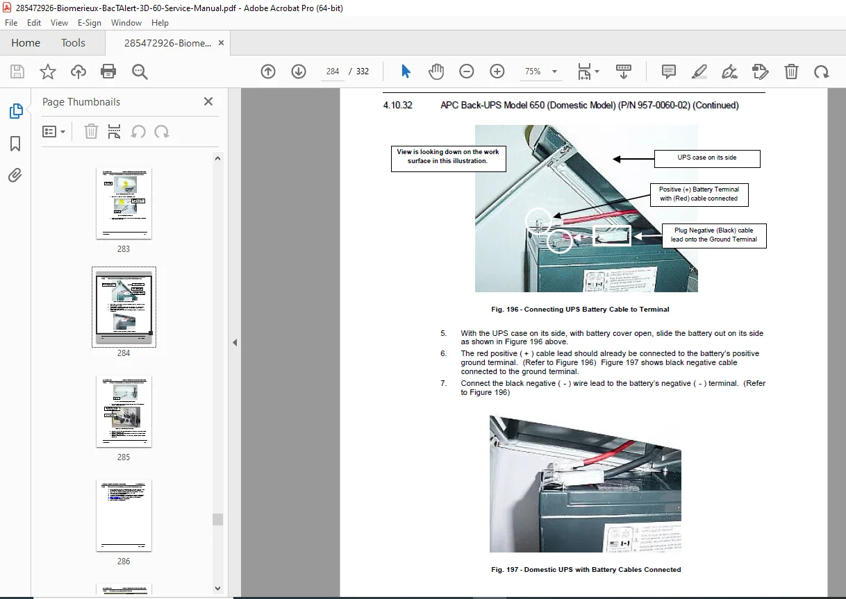
APC Back-UPS Model 650 (Domestic) (P/N 957-0060-02):
- UPS replacement procedures
APC UPS (International Model) (P/N 957-0060-03):
- International UPS installation
Post Service Validation:
- Overview of validation requirements
- Required materials
- Validation procedures
- Performance verification
- Quality control testing
APPENDICES
Appendix A: Glossary
- Technical terminology
- Acronyms and abbreviations
- Industry standard terms
Appendix B: Parts List
- Alphabetical listing
- Part numbers
- Descriptions
- Replacement intervals
Appendix C: Disinfection
- Introduction to disinfection procedures
- Disinfection equipment table
- Spill cleanup procedures
- Instrument shipping preparation
- Assembly decontamination
- Biological safety protocols
Appendix D: Error Codes
- Complete error code listing
- Error descriptions
- Probable causes
- Corrective actions
Appendix E: Diagrams
- Complete electrical schematics
- Wiring diagrams
- Component layout drawings
- System block diagrams
Index:
- Comprehensive alphabetical index
- Cross-references
- Quick topic location
KEY FEATURES OF THIS MANUAL
✓ 332 pages of official BioMérieux factory documentation
✓ Complete electrical schematics with component-level details
✓ Software diagnostics procedures with screenshots
✓ Step-by-step disassembly procedures with over 170 illustrations
✓ Preventive maintenance schedule and procedures
✓ Calibration procedures for optics and temperature
✓ Complete parts list with part numbers
✓ Error code reference with troubleshooting
✓ Power supply testing and adjustment procedures
✓ Installation procedures with site requirements
✓ UPS integration and testing
✓ Disinfection protocols for biological safety
✓ Data backup/restore procedures
✓ Block diagrams for all major assemblies
BACT/ALERT 3D 60 SYSTEM OVERVIEW
Automated Blood Culture System:
- 60-bottle capacity incubator
- Continuous monitoring
- Colorimetric detection technology
- Automated flagging of positive cultures
- Temperature-controlled environment (35°C)
- Gentle agitation system
- Real-time data logging
Clinical Applications:
- Blood culture processing
- Detection of bacteremia
- Detection of fungemia
- Aerobic and anaerobic culture monitoring
- Mycobacteria detection (MB conversion)
Laboratory Integration:
- LIS (Laboratory Information System) interface
- Barcode sample identification
- Automated result reporting
- Data archiving capabilities
WHO NEEDS THIS MANUAL?
- Hospital Clinical Engineering Departments
- Independent Biomedical Equipment Technicians
- Laboratory Equipment Service Companies
- Healthcare Technology Management (HTM) Professionals
- Medical Device Repair Specialists
- Clinical Laboratory Technical Staff
- bioMérieux Authorized Service Centers
- Multi-Vendor Service Organizations
CRITICAL SERVICE PROCEDURES INCLUDED
Diagnostics:
- Software diagnostic screens (complete suite)
- Temperature log analysis
- Flag check calibration
- LED indicator testing
- Communication loopback tests
- Power event log review
Component Replacement:
- CPU and controller boards
- Power supply modules
- Stepper motor assembly
- Thermistor sensors
- ModSig PCBA
- Optical detection components
Calibration:
- Single cell calibration procedures
- Temperature calibration
- Optical alignment
- Power supply voltage adjustment
Preventive Maintenance:
- Scheduled maintenance procedures
- Temperature verification
- UPS testing
- Data backup protocols
INSTANT DOWNLOAD – MINIMIZE LABORATORY DOWNTIME
Keep your blood culture system operational! This official BioMérieux factory service manual provides immediate access to complete diagnostic procedures, electrical schematics, and component-level repair instructions for the BacT/ALERT 3D 60. Whether you’re troubleshooting system errors, replacing circuit boards, calibrating temperature sensors, or performing preventive maintenance, you’ll have the exact same technical documentation used by BioMérieux authorized service engineers. Download instantly and restore your critical laboratory equipment to full operation with professional-grade factory specifications and procedures!
Pricing Rationale:
This is a comprehensive 332-page official factory service manual for the BioMérieux BacT/ALERT 3D 60, a critical automated blood culture system used in hospital microbiology laboratories worldwide. This is sophisticated medical diagnostic equipment requiring specialized service knowledge. Official manufacturer service manuals for clinical laboratory analyzers typically cost $200-400+ from bioMérieux. This manual provides complete technical documentation including detailed electrical schematics, software diagnostic procedures (with multiple test screens), component-level troubleshooting, calibration procedures for optical and temperature systems, complete parts lists with part numbers, and disinfection protocols for biological safety. The BacT/ALERT 3D 60 is essential equipment for detecting life-threatening bloodstream infections, making system uptime critical. At $49.95, this represents exceptional value for biomedical technicians, clinical engineering departments, and laboratory equipment service companies who need immediate access to professional factory documentation to minimize costly equipment downtime and ensure reliable patient testing.