BOBCAT 21002100S LOADER SERVICE REPAIR WORKSHOP MANUAL – PDF DOWNLOAD
Original price was: $68.95.$29.95Current price is: $29.95.
- FILE FORMAT:PDF
- PAGES:382
- DOWNLOADABLE:YES
- MANUAL LANGUAGE:ENGLISH
Description
BOBCAT 21002100S LOADER SERVICE REPAIR WORKSHOP MANUAL – PDF DOWNLOAD
DESCRIPTION:
This manual was written for the trained technician who already possesses knowledge and skills in electrical and mechanical repair. If the technician does not have such knowledge and skills, attempted service or repairs to the vehicle may render the vehicle unsafe. For this reason, Bobcat Company advises that all repairs and/or service be performed by an authorized Bobcat 2100 and 2100S distributor/dealer representative or by a Bobcat factory-trained technician.
It is the policy of Bobcat Company to assist its distributors and dealers in continually updating their service knowledge and facilities so they can provide prompt and efficient service for vehicle owners. Regional technical representatives, vehicle service seminars, periodic service bulletins, maintenance and service manuals, and other service publications also represent Bobcat Company’s continuing commitment to customer support.
SCREENSHOT OF THE MANUAL:


TABLE OF CONTENTS:
SECTION 1 – SAFETY
General Warning 1-1
SECTION 2 – VEHICLE SPECIFICATIONS
SECTION 3 – GENERAL INFORMATION
General Information 3-1
Serial Number Identification 3-1
Storage 3-2
Preparing the Vehicle for Extended Storage 3-2
To Return Vehicle to Service 3-2
SECTION 4 – BODY AND TRIM
Cleaning the Vehicle 4-1
Front Body Repair 4-1
Abrasions and Haze 4-1
Light Scratches 4-2
Large Scratches and Abrasions 4-2
Front Body Components 4-2
Dashboard Removal 4-2
Dashboard Installation 4-2
Front Body Removal 4-3
Front Fender Removal 4-3
Front Fender Installation 4-4
Front Body Installation 4-4
Seat 4-4
Seat Adjustment 4-4
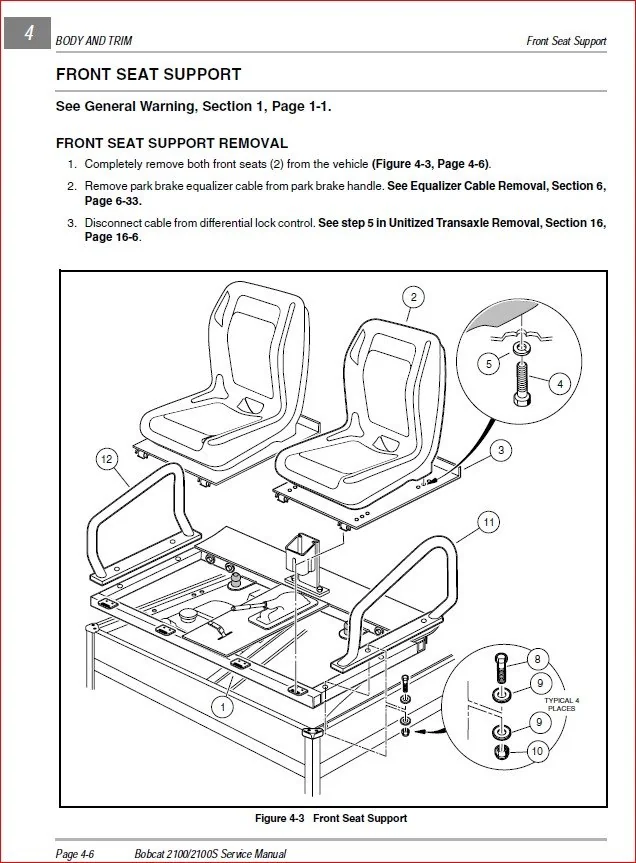
Front Seat Support 4-6
Front Seat Support Removal 4-6
Front Seat Support Installation 4-7
Rear Seat Support 4-7
Rear Seat Support Removal 4-7
Rear Seat Support Installation 4-7
Page iv Bobcat 2100/2100S Service Manual
Cargo Bed 4-9
Cargo Bed Removal 4-9
Cargo Bed Installation 4-9
Bed Stop Bumper Adjustment 4-11
Rear Fender Removal 4-12
Rear Fender Installation 4-12
Tailskirt 4-12
Tailskirt Removal 4-12
Tailskirt Installation 4-12
Receiver Hitch 4-12
Receiver Hitch Removal 4-12
Receiver Hitch Installation 4-13
Floor Mat 4-14
Floor Mat Removal 4-14
Floor Mat Installation 4-14
SECTION 5 – ACCELERATOR AND BRAKE PEDAL ASSEMBLIES
Brake Pedal 5-1
Brake Pedal Removal 5-1
Brake Pedal Installation 5-1
Brake Pedal Adjustment 5-2
Accelerator Pedal 5-4
Accelerator Pedal Removal 5-4
Accelerator Pedal Installation 5-5
Accelerator Pedal Adjustment 5-5
SECTION 6 – MC012C-AS00 TRANSAXLE: HYDRAULIC AND PARK BRAKE
SYSTEMS
Brake System Inspection 6-1
Brake System Troubleshooting 6-3
Brake Drum Removal 6-6
Front Wheel Brake Drum Removal 6-6
Rear Wheel Brake Drum Removal 6-8
Brake Shoe Removal 6-8
Front Brake Shoe Removal 6-8
Rear Brake Shoe Removal 6-9
Brake Cluster Inspection and Cleaning 6-10
Brake Shoe Installation 6-11
Front Brake Shoe Installation 6-12
Rear Brake Shoe Installation 6-12
Bobcat 2100/2100S Service Manual Page v
Brake Drum Installation 6-14
Front Wheel Brake Drum Installation 6-14
Rear Wheel Brake Drum Installation 6-16
Brake Cluster Assembly Replacement 6-17
Front Brake Cluster Assembly Removal 6-17
Front Brake Cluster Assembly Installation 6-17
Rear Brake Cluster Assembly Removal 6-18
Rear Brake Cluster Assembly Installation 6-19
Wheel Cylinder Replacement 6-19
Front Wheel Cylinder Removal 6-19
Front Wheel Cylinder Installation 6-20
Rear Wheel Cylinder Removal 6-20
Rear Wheel Cylinder Installation 6-20
Brake Shoe Adjuster Replacement 6-21
Front Brake Shoe Adjuster Removal 6-22
Front Brake Shoe Adjuster Installation 6-22
Rear Brake Shoe Adjuster Removal 6-22
Rear Brake Shoe Adjuster Installation 6-22
Hydraulic Line and Hose Replacement 6-23
Front Brake Line Removal 6-23
Front Brake Line Installation 6-23
Front Brake Hose Assembly Removal 6-24
Front Brake Hose Assembly Installation 6-24
Rear Brake Line Removal 6-24
Rear Brake Line Installation 6-26
Rear Brake Hose Removal 6-26
Rear Brake Hose Installation 6-27
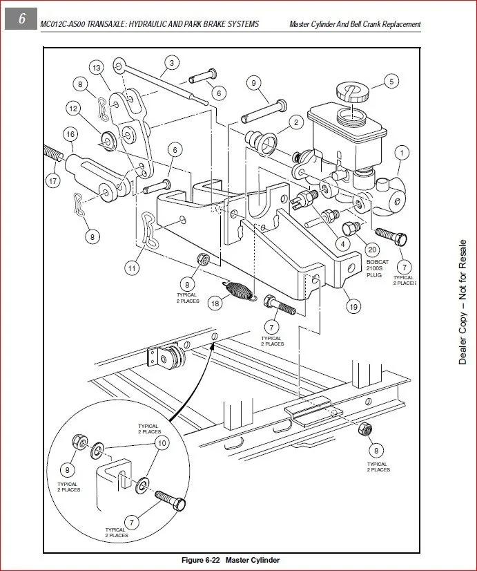
Master Cylinder And Bell Crank Replacement 6-27
Bell Crank Removal 6-27
Bell Crank Installation 6-27
Master Cylinder Removal 6-29
Master Cylinder Installation 6-29
Bleeding the Hydraulic Brake System 6-31
Purging the Hydraulic System 6-32
Filling the Hydraulic System 6-32
Park Brake System 6-33
Park Brake Cable Removal 6-33
Park Brake Cable Installation 6-34
Park Brake Handle Removal 6-35
Park Brake Handle Installation 6-35
Park Brake Adjustment 6-35
Page vi Bobcat 2100/2100S Service Manual
SECTION 7 – STEERING AND FRONT SUSPENSION
Steering Wheel 7-1
Steering Wheel Removal 7-1
Steering Wheel Installation 7-3
Steering Column 7-3
Steering Column Removal 7-3
Steering Column Disassembly 7-3
Steering Column Assembly 7-4
Steering Column Installation 7-4
Rack and Pinion 7-5
Rack and Pinion Removal 7-5
Rack and Pinion Disassembly 7-6
Rack and Pinion Assembly 7-9
Rack and Pinion Installation 7-10
Front Suspension 7-12
Lubrication 7-12
Wheel Alignment 7-12
Front Suspension Components 7-14
Kingpin and Steering Spindle Removal 7-14
Kingpin and Steering Spindle Installation 7-14
A-Arm Removal 7-15
A-Arm Installation 7-17
Shock Absorber Removal 7-17
Shock Absorber Installation 7-18
Front Wheel Bearings and Hubs 7-18
Front Wheel Free Play Inspection 7-18
Front Wheel Bearings and Hub Removal 7-19
Front Wheel Bearings and Hub Installation 7-19
SECTION 8 – WHEELS AND TIRES
General Information 8-1
SECTION 9 – REAR SUSPENSION
Shock Absorbers 9-1
Shock Absorber Removal and Inspection 9-1
Shock Absorber Installation 9-1
Multi-Leaf Springs 9-1
Multi-Leaf Spring Removal 9-1
Multi-Leaf Spring Installation 9-3
Bobcat 2100/2100S Service Manual Page vii
Snubber 9-4
Snubber Removal 9-4
Snubber Installation 9-4
SECTION 10 – PERIODIC MAINTENANCE
Periodic Service Schedule 10-1
Periodic Lubrication Schedule 10-2
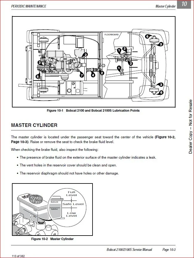
Master Cylinder 10-3
Brake Fluid 10-4
Engine Oil 10-4
Engine Oil Level Check 10-4
Engine Oil and Filter Change 10-5
Oil Viscosity 10-7
Fueling Instructions 10-7
Battery 10-8
SECTION 11 – TROUBLESHOOTING AND ELECTRICAL SYSTEM: FE400 ENGINE
Troubleshooting Guide 11-1
Electrical System 11-5
Wiring Diagram 11-6
Electrical Circuits 11-8
Starter Circuit 11-8
Generator Circuit 11-8
Engine Ignition Circuit 11-9
Engine Kill Circuit 11-9
Reverse Buzzer Circuit 11-10
Low Oil Warning Circuit 11-10
Lockout Cam Circuit 11-11
Fuel Gauge and Sending Unit Circuit 11-12
Hour Meter Circuit 11-13
Lighting Circuit 11-13
Circuit Testing 11-13
Testing the Starter Circuit and Generator Circuit 11-14
Testing the Engine Ignition Circuit 11-15
Testing the Engine Kill Circuit 11-15
Testing the Reverse Buzzer Circuit 11-16
Testing the Low Oil Warning Circuit 11-17
Testing the Lockout Cam Circuit 11-18
Testing the Fuel Gauge and Sending Unit Circuit 11-18
Testing the Lighting Circuit 11-19
Page viii Bobcat 2100/2100S Service Manual
Test Procedures 11-19
Index of Test Procedures 11-19
SECTION 12 – ELECTRICAL COMPONENTS: FE400 ENGINE
Starter/Generator 12-1
Voltage Regulator 12-11
Diode 12-12
Key Switch 12-14
Solenoid 12-15
Fuse 12-15
Lockout Cam Limit Switch 12-17
Lockout Cam 12-17
Reverse Warning Buzzer 12-18
Reverse Buzzer Limit Switch 12-19
Low Oil Warning Light 12-20
Fuel Gauge/Hour Meter 12-21
Fuel Level Sending Unit 12-22
RPM Limiter 12-22
Ignition Coil 12-23
Oil Level Sensor 12-26
Headlights 12-26
Headlight Diode 12-27
Light Switch 12-28
Testing the Light Switch 12-28
Battery 12-28
General Information 12-29
Ground Straps 12-33
SECTION 13 – FE400 ENGINE
General Information 13-1
Before Servicing 13-1
Lubrication System 13-1
Spark Plug 13-1
Cylinder 13-3
Breather Valve (Reed Valve) 13-3
Valve Clearance Check and Adjustment 13-3
Crankcase 13-3
Engine Removal 13-3
Crankcase Cover Removal 13-4
Oil Level Sensor 13-5
Bobcat 2100/2100S Service Manual Page ix
Ignition Coil and Flywheel 13-6
Crankcase Cover Installation 13-7
Flywheel Installation 13-7
Engine Installation 13-8
Torque Specifications 13-9
Adjustment and Settings 13-9
SECTION 14 – FUEL SYSTEM
General Information 14-1
Carburetor 14-1
Main Jet Elevation/Size Chart 14-1
Changing the Main Jet 14-2
Engine Control Linkage 14-5
General Information 14-5
Accelerator Rod 14-6
Governor Cable 14-7
Accelerator Cable 14-8
Closed Throttle or Idle Adjustment 14-10
Engine RPM Adjustment 14-10
Choke and Air Intake System 14-11
Choke Cable Removal 14-11
Choke Cable Installation 14-11
Air Box Removal 14-11
Air Box Installation 14-12
Intake Duct Repair 14-13
Intake Duct Removal 14-13
Intake Duct Installation 14-15
Air Filter 14-16
Fuel Filter Removal 14-17
Fuel Filter Installation 14-17
Fuel Pump 14-17
General Information 14-17
Fuel Pump Removal 14-20
Fuel Pump Disassembly 14-20
Fuel Pump Cleaning and Inspection 14-20
Fuel Pump Assembly 14-21
Fuel Pump Installation 14-21
Fuel Tank 14-22
Fuel Tank Removal 14-22
Fuel Tank Storage or Disposal 14-26
Fuel Tank Installation 14-26
Page x Bobcat 2100/2100S Service Manual
Fuel Lines 14-27
Fuel Shut-Off Valve 14-28
SECTION 15 – EXHAUST SYSTEM
Muffler 15-1
Muffler Removal 15-1
Muffler Installation 15-1
SECTION 16 – MC012C-AS00 UNITIZED TRANSAXLE WITH DIFFERENTIAL LOCK
General Information 16-1
Lubrication 16-2
Axle Shaft 16-3
Axle Shaft, Bearing, and Oil Seal Removal 16-3
Axle Bearing Removal 16-5
Axle Shaft, Bearing, and Oil Seal Installation 16-5
Unitized Transaxle Removal 16-6
Unitized Transaxle Installation 16-16
Forward/Reverse Shifter Cable 16-24
Forward/Reverse Shifter Cable Removal 16-24
Forward/Reverse Shifter Cable Installation 16-24
Forward/Reverse Shifter Cable Adjustment 16-25
Differential Lock System 16-26
Differential Lock System Inspection 16-26
Differential Lock Cable Removal 16-26
Differential Lock Cable Installation 16-27
SECTION 17 – TORQUE CONVERTER
General Information 17-1
Drive Belt 17-3
Drive Belt Removal 17-3
Drive Belt Installation 17-4
Drive Clutch 17-4
Drive Clutch Removal 17-4
Drive Clutch Cleaning and Inspection 17-5
Drive Clutch Disassembly 17-6
Inspection of Drive Clutch Parts 17-7
Drive Clutch Assembly 17-9
Drive Clutch Installation 17-12
Bobcat 2100/2100S Service Manual Page xi
Driven Clutch 17-13
Driven Clutch Removal 17-13
Driven Clutch Disassembly 17-13
Driven Clutch Inspection 17-13
Driven Clutch Assembly 17-15
Driven Clutch Installation 17-17
SECTION 18 – RECONDITIONING THE FE400 ENGINE
General Information 18-1
Recommended Replacement Parts For Engine Teardown 18-2
Before Servicing 18-2
Mechanical Systems 18-2
Cylinder Components 18-4
Cylinder Head 18-4
General Information 18-4
Cylinder Shroud Removal 18-5
Rocker Arm and Push Rod Removal 18-7
Cylinder Head Removal 18-8
Valve Removal 18-8
Breather Valve (Reed Valve) 18-9
Cylinder Head Cleaning and Inspection 18-9
Valve Guides 18-10
Valve Seats 18-11
Valves 18-13
Rocker Arm and Rocker Shaft inspection 18-15
Push Rod Inspection 18-16
Cylinder Head Installation 18-16
Valve Clearance Check and Adjustment 18-17
Breather Valve (Reed Valve) 18-17
Installation of Remaining Engine Components 18-18
Crankcase Components 18-20
Crankcase Cover Removal 18-20
Camshaft and Hydraulic Lifters 18-22
Piston and Connecting Rod 18-24
Cylinder Block 18-26
Ignition Coil and Flywheel 18-28
Oil Pump 18-29
Oil Pressure Relief Valve 18-31
Crankshaft and Counterbalance 18-32
Counterbalance Weight 18-35
Oil Screen 18-38
Ball Bearing 18-38
Oil Seals 18-39
Crankshaft Axial Play Adjustment 18-42
Crankcase Cover Installation 18-44
Engine Assembly 18-45
Engine Installation 18-46
Service Specifications 18-47
Specifications for Resizing Cylinder Bore 18-48
Torque Specifications 18-48
Adjustment and Settings 18-49
SECTION 19 – RECONDITIONING THE MC012C-AS00 UNITIZED TRANSAXLE WITH
DIFFERENTIAL LOCK
Transaxle Model and Identification 19-1
Lubrication 19-2
Axle Shaft 19-3
Unitized Transaxle Removal 19-3
Unitized Transaxle Disassembly 19-5
Component Disassembly 19-7
Differential Gear Lock Housing Disassembly 19-7
Governor Gear Disassembly 19-9
Differential Gear Case Disassembly 19-9
Shifter Fork Disassembly 19-12
Synchronizer Gear Disassembly 19-12
Intermediate Gear Disassembly 19-13
Idler Shaft Disassembly 19-14
Unitized Transaxle Component Inspection 19-15
Idler Shaft Assembly 19-15
Intermediate Gear Assembly 19-16
Synchronizer Gear Assembly 19-16
Shifter Fork Assembly 19-18
Differential Gear Case Assembly 19-19
Governor Gear Assembly 19-21
Differential Gear Lock Housing Assembly 19-21
Unitized Transaxle Assembly 19-22
Unitized Transaxle Installation 19-29
BOBCAT 21002100S LOADER SERVICE REPAIR WORKSHOP MANUAL – PDF DOWNLOAD:
PLEASE NOTE:
This is not a physical manual but a digital manual – meaning no physical copy will be couriered to you. The manual can be yours in the next 2 mins as once you make the payment, you will be directed to the download page IMMEDIATELY.
This is the same manual used by the dealers inorder to diagnose your vehicle of its faults.
Require some other service manual or have any queries: please WRITE to us at [email protected]