Bobcat 325 328 Service Manual 6902745 – PDF DOWNLOAD
$33.95
Bobcat 325 328 Service Manual 6902745 – PDF DOWNLOAD
325 – S/N 234111001 & Above
328 – S/N 234211001 & Above
(G Series)
Description
Bobcat 325 328 Service Manual 6902745 – PDF DOWNLOAD
FILE DETAILS:
Bobcat 325 328 Service Manual 6902745 – PDF DOWNLOAD
Language : English
Pages : 830
Downloadable : Yes
File Type : PDF
Size:23.8 MB
DESCRIPTION:
Bobcat 325 328 Service Manual 6902745 – PDF DOWNLOAD
FOREWORD
This manual is for the Bobcat hydraulic excavator mechanic. It provides necessary servicing an d
adjustment procedures for the hydraulic excavator and its component parts and systems. Refer to the
Operation & Maintenance Manual for operating instructions, starting procedure, daily checks, etc
A general inspection of the following items must be made after the hydraulic excavator has had service
or repair:
• The Delivery Report is used to assure that complete instructions have been given to the new owner and that the machine
is in safe operating condition.
• The Operation & Maintenance Manual delivered with the excavator gives operating information as well as routin e
maintenance and service procedures. It is a part of the excavator and must stay with the machine when it is sol d.
Replacement Operation & Maintenance Manuals can be ordered from your Bobcat Excavator dealer.
• The excavator has machine signs (decals) which instruct on the safe operation and care. The signs and their locations
are shown in the Operation & Maintenance Manual. Replacement signs are available from your Bobcat Excavator dealer.
Safety Alert Symbol: This Safety Symbol is used for important safety messages. When you see this symbol follow
the safety message to avoid personal injury or death.
• The Bobcat Hydraulic Excavator has a plastic Operator’s Handbook fastened to the operator cab. It’s brief instructions
are convenient to the operator. The handbook is available from your dealer in an English, French, German, Dutch, Italian,
Spanish, Portugese, Finnish, Danish, and Swedish editions.
• The CIMA Safety Manual delivered with the excavator gives information for safe operating and standard signals.
• The Service Manual and Parts Manual are available from your dealer for use by mechanics to do shop–type service and
repair work.
• The Bobcat compact Excavator Operator Training Course is available through your local dealer
TABLE OF CONTENTS:
Bobcat 325 328 Service Manual 6902745 – PDF DOWNLOAD
MAINTENANCE SAFETY 3
ALPHABETICAL INDEX 5
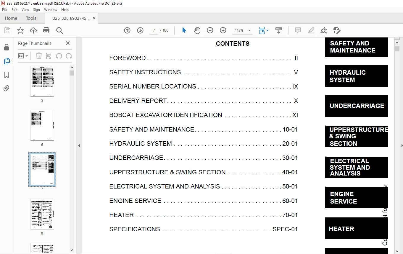
CONTENTS 7
FOREWORD 8
SAFETY INSTRUCTIONS 11
FIRE PREVENTION 13
Maintenance 13
Operation 13
Electrical 13
Hydraulic System 13
Fueling 13
Starting 13
Spark Arrestor Exhaust System 13
Welding And Grinding 14
Fire Extinguishers 14
SERIAL NUMBER LOCATIONS 15
Excavator Serial Number 15
Engine Serial Number 15
DELIVERY REPORT 16
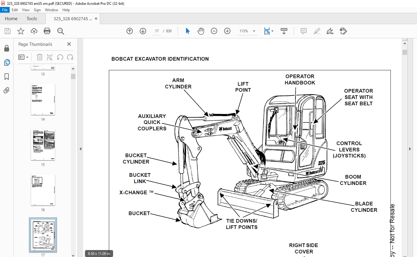
BOBCAT EXCAVATOR IDENTIFICATION 17
SAFETY AND MAINTENANCE 19
LIFTING AND BLOCKING THE EXCAVATOR 21
Procedure 21
UPPERSTRUCTURE SLEW LOCK 23
Operation (Early Models) 23
Operation (Later Models) 23
LIFTING THE EXCAVATOR 25
Procedure 25
OPERATOR CAB (ROPS/TOPS) 27
Emergency Exit 27
Front Window 28
Right Side Windows 30
Cab Door 31
TRANSPORTING THE EXCAVATOR 33
Procedure 33
TAILGATE 35
Opening And Closing The Tailgate 35
Adjusting The Bumper 35
Adjusting The Latch 35
RIGHT SIDE COVER 37
Opening And Closing The Right Side Cover 37
SERVICE SCHEDULE 39
Chart 39
AIR CLEANER 41
Daily Check 41
Replacing The Filters 41
HEATER AIR FILTER (WITH CAB OPTION ONLY) 43
Removal And Installation 43
COOLING SYSTEM 45
Cleaning The Cooling System 45
Checking Coolant Level 46
Replacing The Coolant 47
FUEL SYSTEM 49
Fuel Specifications 49
Filling The Fuel Tank 49
Removing Water From The Fuel Filter 50
Draining The Fuel Tank 50
Fuel Filter 51
Removing Air From The Fuel System 51
ENGINE LUBRICATION SYSTEM 53
Checking Engine Oil 53
Oil Chart 53
Replacing Oil And Filter 54
HYDRAULIC SYSTEM 55
Checking And Adding Hydraulic Oil 55
Replacing The Hydraulic Oil 56
Replacing The Hydraulic Filter 57
Replacing The Case Drain Filter 58
Diagnostic Couplers 58
LUBRICATION OF THE HYDRAULIC EXCAVATOR 61
TRAVEL MOTOR 65
Checking Oil Level 65
Draining The Travel Motor 65
SPARK ARRESTOR MUFFLER 67
ENGINE ACCESSORY DRIVE BELT 69
Belt Tension 69
Belt Adjustment 69
SEAT BELT 71
Inspection And Maintenance 71
HYDRAULIC SYSTEM 73
HYDRAULIC / HYDROSTATIC SCHEMATIC 79
HYDRAULIC SYSTEM INFORMATION 81
Glossary Of Hydraulic/Hydrostatic Symbols For Excavators 81
Troubleshooting Chart 84
Troubleshooting The Hydraulic Circuit 84
Troubleshooting The Cylinder Circuit 85
Troubleshooting The Swing (Upperstructure Slew) Circuit 86
Troubleshooting The Travel Circuit 87
BOOM CYLINDER 89
Testing 89
Removal And Installation 92
Parts Identification 95
Disassembly 96
Assembly 98
ARM CYLINDER 101
Testing 101
Removal And Installation 103
Parts Identification 105
Disassembly 106
Assembly 108
BOOM SWING CYLINDER 111
Testing 111
Removal And Installation 113
Parts Identification 115
Disassembly 116
Assembly 118
BUCKET CYLINDER 121
Testing 121
Removal And Installation 123
Parts Identification 124
Disassembly 125
Assembly 127
BLADE CYLINDER 131
Testing 131
Removal And Installation 133
Parts Identification 134
Disassembly 135
Assembly 137
CLAMP CYLINDER 141
Testing 141
Removal And Installation 142
Parts Identification 143
Disassembly 144
Assembly 147
MAIN RELIEF VALVES 153
Testing And Adjusting The Main Relief Valves 153
PORT RELIEF VALVES 157
Testing And Adjusting The Port Relief Valves 157
CROSSPORT RELIEF VALVES 159
Testing And Adjusting The Crossport Relief Valves 159
PRESSURE REDUCING VALVE 163
Testing And Adjusting The Pressure Reducing Valve 163
HYDRAULIC CONTROL VALVE 165
Description 165
Removal And Installation 166
Control Valve Identification 173
Disassembly 174
Right Travel Valve Section Disassembly And Assembly 176
Boom Swing Valve Section Disassembly And Assembly 182
Boom Valve Section Disassembly And Assembly 189
Left Travel Valve Section Disassembly And Assembly 193
Arm Valve Section Disassembly And Assembly 198
Bucket Valve Section Disassembly And Assembly 202
Auxiliary Valve Section Disassembly And Assembly 206
Boost Valve Section Disassembly And Assembly 210
Blade Valve Section Disassembly And Assembly 214
Slew Valve Section Disassembly And Assembly 219
Assembly 223
HYDRAULIC PUMP (S/N 234111001-23412473) & (S/N 234211001-234212268) 231
Description 231
Torque Adjustment 232
Testing The Piston Pump 233
Testing The Gear Pump 235
Testing Auxiliary Hydraulic Flow 236
Removal And Installation 237
Coupler Removal And Installation 239
Hydraulic Pump Start Up 240
Gear Pump Parts Identification 241
Piston Pump Parts Identification 242
Disassembly 243
Gear Pump Disassembly 244
Gear Pump Assembly 247
Piston Pump Disassembly 250
Piston Pump Assembly 258
Assembly 266
HYDRAULIC PUMP (S/N 234112474 & Above) & (S/N 234212269 & Above) 269
Description 269
Torque Adjustment 270
Testing The Piston Pump 271
Testing The Gear Pump 273
Testing Auxiliary Hydraulic Flow 275
Removal And Installation 276
Coupler Removal And Installation 277
Hydraulic Pump Start Up 278
Gear Pump Parts Identification 279
Piston Pump Parts Identification 280
Disassembly 281
Gear Pump Disassembly 282
Gear Pump Assembly 285
Piston Pump Disassembly 288
Piston Pump Assembly 294
MANIFOLD ASSEMBLY/ ACCUMULATOR 301
Description 301
Removal And Installation 301
Parts Identification 305
Disassembly 306
Assembly 316
MANIFOLD ASSEMBLY 327
Parts Identification 327
Disassembly 328
Assembly 338
TRAVEL MOTOR 351
Removal And Installation 351
Parts Identification 352
Disassembly 353
Assembly 361
SWIVEL JOINT 371
Description 371
Removal And Installation 371
Parts Identification 373
Disassembly 374
Assembly 375
SWING MOTOR 379
Removal And Installation 379
Parts Identification 382
Disassembly 383
Assembly 388
SWING MOTOR DRIVE CARRIER 395
Removal And Installation 395
Parts Identification 396
Disassembly 397
Assembly 399
CONTROL PATTERN SELECTOR VALVE 403
Removal And Installation 403
Parts Identification 404
Disassembly 405
Assembly 406
RIGHT CONTROL LEVER (JOYSTICK) 407
Testing 407
Handle Removal And Installation 408
Joystick Assembly, Removal And Installation 412
Parts Identification 415
Disassembly 416
Assembly 421
LEFT CONTROL LEVER (JOYSTICK) 425
Testing 425
Handle Removal And Installation 426
Joystick Assembly Removal And Installation 429
Parts Identification 431
Disassembly 432
Assembly 437
HYDRAULIC FILTER MOUNT 443
Removal And Installation 443
HYDRAULIC RESERVOIR 445
Removal And Installation 445
OIL COOLER 447
Removal And Installation 447
DIRECT TO TANK VALVE 449
Removal And Installation 449
Disassembly And Assembly 450
BUILD UP VALVE 451
Description 451
Removal And Installation 451
Parts Identification 452
Disassembly And Assembly 453
CASE DRAIN FILTER 455
Removal And Installation 455
UNDERCARRIAGE 457
BLADE 459
Removal And Installation 459
TRACKS 461
Track Lug Height 461
Adjustment 461
Rubber Track Removal And Installation 464
Steel Track Removal And Installation 466
TRACK FRAME 469
Disassembly And Assembly 469
Recoil Spring Cylinder Disassembly And Assembly 471
Recoil Spring Cylinder Parts Identification (with Replaceable Shaft) 472
Recoil Spring Assembly And Cylinder Disassembly And Assembly (With Replaceable Shaft) 473
TRACK DAMAGE IDENTIFICATION 475
Cutting Of Steel Cords 475
Abrasion Of Embedded Metals 476
Separation Of Embedded Metals 477
Separation Of Embedded Metals Due To Corrosion 478
Cuts On The Lug Side Rubber 479
Cracks On The Lug Side Rubber Due To Fatigue 480
Lug Abrasion 481
Cracks And Cuts On The Lug Side Rubber 482
Abrasion Of The Track Roller Side 483
Cuts On The Edges Of Track Roller Side 484
TRACK IDLER 487
Parts Identification 487
Disassembly 488
Assembly 490
TRACK ROLLER 493
Parts Identification 493
Disassembly 494
Assembly 496
SWING CIRCLE GEAR 499
Swing Bearing Removal 499
Swing Bearing Installation 500
UPPERSTRUCTURE & SWING SECTION 501
UPPERSTRUCTURE 505
Removal 505
Installation 508
ROPS CANOPY 511
Removal And Installation 511
CAB 515
Removal And Installation 515
Door Removal And Installation 520
Front Window Removal And Installation 521
Right Side Rear Sliding Window Removal And Installation 524
Right Side Front Sliding Window Removal And Installation 524
Right Side Front And Rear Sliding Window Weather Strip Removal And Installation 525
Right Side Front And Rear Sliding Window Wiper Strip Removal And Installation 525
Glass Removal 526
Glass Installation 527
STANDARD SEAT AND SEAT MOUNT 529
Removal And Installation 529
SUSPENSION SEAT AND SEAT MOUNT 531
Removal And Installation 531
RIGHT CONSOLE 533
Console Cover Removal And Installation 533
Console Base Removal And Installation 534
LEFT CONSOLE 537
Lower Console Cover Removal And Installation 537
Upper Console Cover Removal And Installation 539
Compression Spring Removal And Installation 540
Compression Spring Disassembly And Assembly 541
Lock Lever Removal And Installation 543
Console Removal And Installation 544
Disassembly And Assembly 548
Console Switch Removal And Installation 551
Console Base Removal And Installation 552
ENGINE SPEED CONTROL 553
Removal And Installation 553
Adjustment (Later Models) 554
BLADE CONTROL 555
Lever Removal And Installation 555
Linkage Removal And Installation 556
Linkage Bar Removal And Installation 558
Lower Linkage Removal And Installation 560
RIGHT PEDAL AND LINKAGE 563
Pedal Removal And Installation 563
Pedal Disassembly And Assembly 564
Linkage Removal And Installation 566
TRAVEL CONTROLS 567
Removal And Installation 567
Disassembly And Assembly 568
Adjustment 571
FLOOR MAT AND FLOOR PLATE 575
Removal And Installation (Canopy Equipped Excavators) 575
Removal And Installation (Cab Equipped Excavators) 576
FUEL TANK 577
Removal And Installation 577
HORN 581
Removal And Installation (Early Models) 581
Removal And Installation (Later Models) 582
SWING FRAME 583
Boom Swing Bracket Removal And Installation 583
Boom Swing Bracket Hose Installation 587
Bushing Removal 588
Bushing Installation 589
BOOM 591
Removal And Installation 591
ARM 593
Removal And Installation 593
Arm To Boom Bushing Removal And Installation 593
Arm To Bucket And Bucket Link Bushing Removal And Installation 594
BUCKET 595
Bucket Teeth Removal And Installation 595
Bucket Side Cutting Edge Removal And Installation 596
CLAMP 597
Removal And Installation 597
TAILGATE 599
Removal And Installation 599
Latch Removal And Installation 600
X-CHANGE 601
Removal And Installation 601
Disassembly 603
Assembly 607
Check Proper Latch Engagement 613
UPPERSTRUCTURE SLEW LOCK 617
Removal And Installation (Early Models) 617
Removal And Installation (Later Models) 618
Disassembly And Assembly (Later Models) 618
RIGHT SIDE COVER 621
Removal And Installation 621
ELECTRICAL SYSTEM AND ANALYSIS 623
ELECTRICAL SCHEMATIC 625
ELECTRICAL SYSTEM INFORMATION 627
Troubleshooting Chart 627
Description 628
Fuse And Relay Location 628
BATTERY 629
Servicing 629
Removing And Installing The Battery 630
Using A Booster Battery (Jump Starting) 631
ALTERNATOR 633
Engine Accessory Drive Belt 633
Engine Accessory Drive Belt Tensioner Removal And Installation 634
Removal And Installation 635
Bracket Removal And Installation 636
Description 637
Tests 637
Alternator Output Test 638
Full Field Test 638
Alternator Regulator Test 639
Parts Identification 640
Disassembly And Assembly 641
Rotor Continuity Test 645
Rotor Continuity Test 646
Rectifier Continuity (Diode) Test 646
STARTER 647
Removal And Installation 647
Parts Identification 648
Disassembly 649
Inspection And Repair 654
Assembly 657
LIGHTS 663
Removal And Installation 663
Boom Light Removal And Installation (Early Models) 664
Boom Light Disassembly And Assembly (Early Models) 664
Boom Light Removal And Installation (Later Models) 665
Boom Light Bulb Replacement (Later Models) 665
TWO SPEED SWITCH 667
Removal And Installation 667
FUEL LEVEL SENDER 669
Removal And Installation 669
Testing 669
DIAGNOSTICS SERVICE CODE 671
Number Codes List 671
DELUXE INSTRUMENT PANEL SETUP 673
Passwords 673
Password Entry (For Starting And Operating The Machine) 673
Changing The Owner or Operator Password 673
Password Lockout Feature 674
Job Clock 674
RPM 674
ENGINE SERVICE 675
TROUBLESHOOTING 677
Chart 677
MUFFLER 679
Removal And Installation 679
AIR CLEANER 681
Removal And Installation 681
RADIATOR 683
Removal And Installation 683
ENGINE COMPONENTS AND TESTING 685
Engine Compression Checking 685
Glow Plugs Removal And Installation 686
Checking The Glow Plug 687
Fuel Shut-Off Solenoid Removal And Installation 688
Fuel Injection Pump Check 690
Fuel Injection Pump Removal And Installation 691
Fuel Injection Pump Timing 694
Fuel Injector Nozzles Removal And Installation 696
Fuel Injector Nozzle Check 698
Valve Clearance Adjustment 699
ENGINE 701
Removal And Installation 701
ENGINE FLYWHEEL (EARLY MODELS) 707
Flywheel Removal And Installation 707
Hydraulic Pump Coupler 709
Flywheel Ring Gear 709
ENGINE FLYWHEEL (LATER MODELS) 711
Flywheel Removal And Installation 711
Hydraulic Pump Coupler 713
Flywheel Ring Gear 714
RECONDITIONING THE ENGINE 715
Cylinder Head Removal And Installation 715
Cylinder Head Disassembly And Assembly 718
Cylinder Head Servicing 719
Cylinder Head Top Clearance 719
Valve Guide Checking 720
Reconditioning The Valve And Valve Seat 722
Valve Spring 723
Rocker Arm And Shaft Checking 724
Timing Gearcase Cover Removal And Installation 724
Idler Gear And Camshaft Removal And Installation 727
Camshaft Servicing 728
Idler Gear And Shaft Servicing 729
Timing Gears Checking Backlash 730
Fuel Camshaft Removal And Installation 730
Fuel Camshaft Governor 731
Crankshaft Gear Removal And Installation 731
Oil Pump Removal And Installation 732
Oil Pump Service 732
Checking Engine Oil Pressure 733
Valve Tappets 734
Piston And Connecting Rod Removal And Installation 734
Piston And Connecting Rod Servicing 736
Connecting Rod Alignment 738
Crankshaft And Bearings Removal And Installation 739
Crankshaft And Bearings, Servicing 741
Cylinder Bore, Checking 745
Water Pump Removal And Installation 745
Water Pump Disassembly And Assembly 746
HEATER 747
HEATER SYSTEM 749
Description 749
Components 749
REGULAR MAINTENANCE 751
Filter Element Removal And Installation 751
Heater Coil 752
TROUBLESHOOTING 753
Blower Motor Does Not Operate 753
Blower Motor Operates Normally, But Air Flow Is Insufficient 753
Electrical System 754
HEATER UNIT (EARLY MODELS) 759
Removal And Installation 759
HEATER UNIT (LATER MODELS) 761
Removal And Installation 761
HEATER COIL (EARLY MODELS) 763
Removal And Installation 763
HEATER COIL (LATER MODELS) 765
Removal And Installation 765
BLOWER FAN (EARLY MODELS) 767
Removal And Installation 767
Disassembly And Assembly 768
Resistor Removal And Installation 769
Wire Connector Removal And Installation 770
BLOWER FAN (LATER MODELS) 773
Removal And Installation 773
Disassembly And Assembly 774
Resistor Removal And Installation 775
HEATER VALVE (EARLY MODELS) 777
Removal And Installation 777
HEATER VALVE (LATER MODELS) 779
Removal And Installation 779
SPECIFICATIONS 781
SPECIFICATIONS 783
325/328 Excavator Machine Dimensions 783
325 Excavator Machine Dimensions 784
328 Excavator Machine Dimensions 785
Performance 786
Controls 786
Engine 786
Hydraulic System 787
Hydraulic Cylinders 787
Hydraulic Cycle Times 788
Drive System 788
Undercarriage 788
Track 789
Electrical 789
ENGINE SPECIFICATIONS 791
Fuel Injection Nozzles 791
Fuel Injection Pump 791
Cylinder Head 791
Valves 791
Valve Springs 792
Valve Timing 792
Rocker Arms 792
Camshaft 792
Tappet 792
Cylinders 793
Piston Rings 793
Pistons 793
Connecting Rods 793
Oil Pump 793
Crankshaft 794
Timing Gear 794
Thermostat 795
Engine Bolt Torque 795
Crankshaft Re-Grind Data 796
TORQUE SPECIFICATIONS 797
Torque for General SAE Bolts 797
Torque For General Metric Bolts 798
HYDRAULIC CONNECTION SPECIFICATIONS 799
O-ring Face Seal Connection 799
Straight Thread O-ring Fitting 799
Tubelines And Hoses 799
Flare Fitting 800
O-ring Flare Fitting 801
Port Seal Fitting 803
HYDRAULIC FLUID SPECIFICATIONS 807
Specifications 807
FUEL, COOLANT AND LUBRICANTS 809
Chart 809
CONVERSIONS 811
Decimal And Millimeter Equivalents 811
U S To Metric Conversion 812
SERVICE MANUAL REVISIONS 813
Revision No: 325/328-1 813
Revision No: 325/328-2 815
Revision No: 325/328-3 817
Revision No: 325/328-4 819
Revision No: 325/328-5 821
Revision No: 325/328-6 823
Revision No: 325/328-7 825
Revision No: 325/328-8 827
Revision No: 325/328-9 829
IMAGES PREVIEW OF THE MANUAL:
Need help? Contact: [email protected]
https://vimeo.com/840693878?share=copy
PLEASE NOTE:
- This is the same manual used by the dealers to diagnose and troubleshoot your vehicle
- You will be directed to the download page as soon as the purchase is completed. The whole payment and downloading process will take anywhere between 2-5 minutes
- Need any other service / repair / parts manual, please feel free to contact [email protected] . We still have 50,000 manuals unlisted
s.m