Bobcat 329 Compact Excavator Service Manual 6904771 (7-12) – PDF DOWNLOAD
$34.95
Bobcat 329 Compact Excavator Service Manual 6904771 (7-12) – PDF DOWNLOAD
S/N A2PG11001 & Above
Description
Bobcat 329 Compact Excavator Service Manual 6904771 (7-12) – PDF DOWNLOAD
FILE DETAILS:
Bobcat 329 Compact Excavator Service Manual 6904771 (7-12) – PDF DOWNLOAD
Language : English
Pages : 794
Downloadable : Yes
File Type : PDF
Size:23.2 MB
DESCRIPTION:
Bobcat 329 Compact Excavator Service Manual 6904771 (7-12) – PDF DOWNLOAD
FOREWORD
This manual is for the Bobcat excavator mechanic. It provides necessary servicing and adjustment
procedures for the Bobcat excavator and its component parts and systems. Refer to the Operation &
Maintenance Manual for operating instructions, starting procedure, daily checks, etc.
A general inspection of the following items must be made after the excavator has had service or repair:
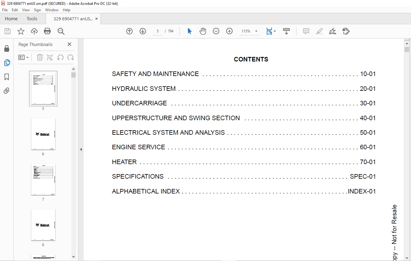
TABLE OF CONTENTS:
Bobcat 329 Compact Excavator Service Manual 6904771 (7-12) – PDF DOWNLOAD
MAINTENANCE SAFETY 3
CONTENTS 5
FOREWORD 7
FOREWORD 9
SAFETY INSTRUCTIONS 11
FIRE PREVENTION 13
Maintenance 13
Operation 13
Electrical 13
Hydraulic System 13
Fueling 13
Starting 13
Spark Arrester Exhaust System 13
Welding And Grinding 14
Fire Extinguishers 14
SERIAL NUMBER LOCATIONS 15
Excavator Serial Number 15
Engine Serial Number 15
DELIVERY REPORT 16
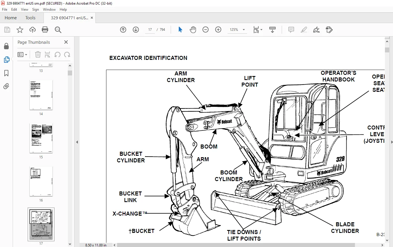
EXCAVATOR IDENTIFICATION 17
SAFETY AND MAINTENANCE 19
LIFTING AND BLOCKING THE EXCAVATOR 23
Procedure 23
UPPERSTRUCTURE SLEW LOCK 25
Operation 25
LIFTING THE EXCAVATOR 27
Procedure 27
OPERATOR CAB (ROPS / TOPS) 29
Description 29
Cab Door 29
Front Window 30
Front Wiper 31
Window Washer Reservoir 31
Right Side Window 32
Heating, Ventilation And Air Conditioning Duct 33
TRANSPORTING THE EXCAVATOR ON A TRAILER 35
Loading And Unloading 35
Fastening 35
TAILGATE 37
Opening And Closing 37
Adjusting The Bumper 37
Adjusting The Latch 37
RIGHT SIDE COVER 39
Opening And Closing 39
Adjusting The Latch 39
SERVICE SCHEDULE 41
Chart 41
AIR CLEANER SERVICE 43
Daily Check 43
Replacing Filter Elements 43
ENGINE COOLING SYSTEM 45
Cleaning 45
Checking Level 45
Removing And Replacing Coolant 46
FUEL SYSTEM 49
Fuel Specifications 49
Filling The Fuel Tank 49
Fuel Filter 50
Draining The Fuel Tank 50
Removing Air From The Fuel System 51
ENGINE LUBRICATION SYSTEM 53
Checking And Adding Engine Oil 53
Engine Oil Chart 53
Removing And Replacing Oil And Filter 54
HYDRAULIC SYSTEM 55
Checking And Adding Fluid 55
Hydraulic Fluid Chart 55
Removing And Replacing Hydraulic Filters 56
Removing And Replacing Hydraulic Fluid 57
LUBRICATING THE EXCAVATOR 59
Lubrication Locations 59
TRAVEL MOTOR 63
Checking And Adding Oil 63
Removing And Replacing Oil 63
SPARK ARRESTER MUFFLER 65
Cleaning Procedure 65
ALTERNATOR BELT 67
Belt Adjustment 67
Belt Replacement 67
SEAT BELT 69
Inspection And Maintenance 69
PIVOT PINS 71
Inspection And Maintenance 71
EXCAVATOR STORAGE AND RETURN TO SERVICE 73
Storage 73
Return To Service 73
STOPPING THE ENGINE AND LEAVING THE EXCAVATOR 75
Procedure 75
Emergency Exits 76
REMOTE START TOOL KIT – MEL1563 77
Remote Start Tool – MEL1563 77
Service Tool Harness Communicator – MEL1566 79
REMOTE START TOOL (SERVICE TOOL) KIT – 7003031 81
Description 81
Remote Start Tool (Service Tool) – 7003030 82
Excavator Service Tool Harness – 6689747 83
Computer Service Tool Harness – 6689746 84
HYDRAULIC SYSTEM 85
HYDRAULIC / HYDROSTATIC SCHEMATICS 89
HYDRAULIC SYSTEM INFORMATION 91
Glossary Of Hydraulic / Hydrostatic Symbols 91
Troubleshooting The Hydraulic Circuit 95
Troubleshooting The Cylinder Circuit 96
Troubleshooting The Swing (Upperstructure Slew) Circuit 97
Troubleshooting The Travel Circuit 98
CYLINDER (BOOM) 99
Testing 99
Removal And Installation 101
Parts Identification 103
Disassembly 104
Assembly 106
CYLINDER (ARM) 111
Testing 111
Removal And Installation 113
Parts Identification 115
Disassembly 116
Assembly 118
CYLINDER (BOOM SWING) 123
Testing 123
Removal And Installation 125
Parts Identification 127
Disassembly 128
Assembly 130
CYLINDER (BUCKET) 133
Testing 133
Removal And Installation 135
Parts Identification 137
Disassembly 138
Assembly 140
CYLINDER (BLADE) 143
Testing 143
Removal And Installation 145
Parts Identification 146
Disassembly 147
Assembly 149
CYLINDER (CLAMP) 153
Testing 153
Removal And Installation 154
Parts Identification 155
Disassembly 156
Assembly 159
VALVE (MAIN RELIEF) 165
Testing And Adjusting The Main Relief Valve 165
VALVES (PORT RELIEF) 171
Testing And Adjusting Port Relief Valve Pressure 171
VALVES (CROSSPORT RELIEF) 173
Testing And Adjusting The Crossport Relief Valves 173
VALVE (PRESSURE REDUCING) 179
Testing And Adjusting The Pressure Reducing Valve 179
HYDRAULIC CONTROL VALVE 181
Description 181
Removal And Installation 182
Control Valve Identification 189
Disassembly 190
Right Travel Valve Section Disassembly And Assembly 192
Boom Swing Valve Section Disassembly And Assembly 197
Boom Valve Section Disassembly And Assembly 204
Left Travel Valve Section Disassembly And Assembly 208
Arm Valve Section Disassembly And Assembly 213
Bucket Valve Section Disassembly And Assembly 217
Auxiliary Valve Section Disassembly And Assembly 221
Boost Valve Section Disassembly And Assembly 225
Blade Valve Section Disassembly And Assembly 229
Slew Valve Section Disassembly And Assembly 234
Assembly 238
HYDRAULIC PUMP 245
Description 245
Torque Adjustment 246
Testing The Piston Pump 247
Testing The Gear Pump 249
Testing Auxiliary Hydraulic Flow 250
Removal And Installation 251
Coupler Removal And Installation 253
Parts Identification (Gear Pump) 254
Parts Identification (Piston Pump) 255
Disassembly 256
Gear Pump Disassembly 257
Gear Pump Assembly 260
Piston Pump Disassembly 263
Piston Pump Assembly 269
Assembly 275
MANIFOLD ASSEMBLY / ACCUMULATOR ASSEMBLY 277
Description 277
Removal And Installation 277
Parts Identification 281
Disassembly 282
Assembly 292
TRAVEL MOTOR 303
Description 303
Removal And Installation 303
Parts Identification 305
Disassembly 306
Assembly 316
SWIVEL JOINT 327
Description 327
Removal And Installation 327
Parts Identification 329
Disassembly 330
Assembly 331
SWING MOTOR 335
Description 335
Removal And Installation 335
Parts Identification 338
Disassembly 339
Assembly 344
SWING MOTOR (DRIVE CARRIER) 351
Description 351
Removal And Installation 351
Parts Identification 352
Disassembly 353
Assembly 355
CONTROL PATTERN SELECTOR VALVE 359
Description 359
Removal And Installation 359
Parts Identification 360
Disassembly 361
Assembly 362
RIGHT CONTROL LEVER (JOYSTICK) 363
Description 363
Testing 363
Handle Removal And Installation 364
Removal And Installation 368
Parts Identification 371
Disassembly 372
Assembly 377
LEFT CONTROL LEVER (JOYSTICK) 383
Description 383
Testing 383
Handle Removal And Installation 384
Removal And Installation 387
Parts Identification 389
Disassembly 390
Assembly 395
HYDRAULIC FILTER 401
Description 401
Housing Removal And Installation 401
CASE DRAIN FILTER 403
Description 403
Housing Removal And Installation 403
HYDRAULIC RESERVOIR 405
Description 405
Removal And Installation 405
OIL COOLER 407
Description 407
Removal And Installation 407
DIRECT TO TANK VALVE 409
Description 409
Removal And Installation 409
Parts Identification 411
Disassembly And Assembly 412
BUILDUP VALVE 415
Description 415
Removal And Installation 415
Parts Identification 416
Disassembly And Assembly 417
UNDERCARRIAGE 419
BLADE 421
Description 421
Removal And Installation 421
TRACK FRAME COMPONENTS 423
Description 423
Track Lug Height 423
Checking Tension 424
Adjusting Tension 425
Rubber Track Removal And Installation 427
Steel Track Removal And Installation 430
Idler (Front) Removal And Installation 433
Idler (Front) Parts Identification 434
Idler (Front) Disassembly 435
Idler (Front) Assembly 437
Coil Spring Assembly And Cylinder Disassembly And Assembly (W/O Replaceable Shaft) 440
Cylinder Parts Identification (With Replaceable Shaft) 441
Coil Spring Assembly And Cylinder Disassembly And Assembly (With Replaceable Shaft) 442
Roller Removal And Installation 443
Roller Parts Identification 444
Roller Disassembly 445
Roller Assembly 447
Track Guide Removal And Installation 449
Sprocket Removal And Installation 449
Track Damage Identification 450
SWING CIRCLE GEAR 461
Removal And Installation 461
UPPERSTRUCTURE AND SWING SECTION 463
UPPERSTRUCTURE 467
Description 467
Removal 467
Installation 470
CANOPY 473
Removal And Installation 473
CAB 477
Removal And Installation 477
Door Removal And Installation 482
Front Window Removal And Installation 483
Right Side Rear Sliding Window Removal And Installation 486
Right Side Front Sliding Window Removal And Installation 486
Glass Removal 487
Right Side Front And Rear Sliding Window Weather Strip Removal And Installation 488
Right Side Front And Rear Sliding Window Wiper Strip Removal And Installation 488
Glass Installation 489
SEAT AND SEAT MOUNT 495
Seat Mount Removal And Installation 495
Seat Removal And Installation 496
RIGHT CONSOLE 497
Description 497
Console Cover Removal And Installation 497
Console Frame Removal And Installation 498
LEFT CONSOLE 501
Description 501
Joystick Console Cover (Bottom) Removal And Installation 501
Joystick Console Cover (Top) Removal And Installation 502
Compression Spring Removal And Installation 503
Compression Spring Disassembly And Assembly 503
Lever Removal And Installation 505
Joystick Console Frame Removal And Installation 506
Joystick Console Frame Disassembly And Installation 507
Left Rear Console Cover Removal And Installation 508
Left Rear Console Frame Removal And Installation 509
Left Rear Console Frame Disassembly And Assembly 511
BLADE CONTROL 513
Removal And Installation 513
Disassembly And Assembly 513
Linkage Removal And Installation 514
Linkage Disassembly And Assembly 516
UPPERSTRUCTURE SLEW LOCK 519
Removal And Installation (S/N A2PG11001 – A2PG11093) 519
Removal And Installation (S/N A2PG11094 & Above) 520
Disassembly And Assembly (S/N A2PG11094 & Above) 520
FLOOR MAT AND FLOOR PANEL 523
Description 523
Removal And Installation 523
BOOM SWING PEDAL 527
Description 527
Removal And Installation 527
Disassembly And Assembly 528
Linkage Removal And Installation 530
TRAVEL LEVERS / PEDALS 531
Description 531
Adjustment 531
Removal And Installation 534
Disassembly And Assembly 534
FUEL TANK 537
Removal And Installation 537
HORN 541
Removal And Installation (Earlier Models) 541
Removal And Installation (Later Models) 542
SWING FRAME 543
Description 543
Removal And Installation 543
Hose Routing 547
Bushing Removal And Installation 548
Swing Frame Bushing Removal And Installation 548
BOOM 551
Description 551
Removal And Installation 551
ARM 555
Description 555
Removal And Installation 555
Arm To Boom Bushing Removal And Installation 556
Arm To Bucket And Bucket Link Bushing Removal And Installation 557
BUCKET 559
Removal And Installation (Pin-On X-Change™) 559
Removal And Installation (Bolt-On X-Change™) 565
Removal And Installation (Pin-On Attachment) 571
Bucket Teeth Removal And Installation 572
Bucket Side Cutting Edge Removal And Installation 573
CLAMP 575
Removal And Installation 575
TAILGATE 577
Removal And Installation 577
Latch Removal And Installation 578
X-CHANGE 579
Pin-On Removal And Installation 579
Pin-On Disassembly And Assembly 580
RIGHT SIDE COVER 581
Removal And Installation 581
QUICK COUPLER (KLAC™ SYSTEM) 583
Troubleshooting 583
Daily Inspection 583
Removal And Installation 584
Parts Identification 586
Disassembly 587
Assembly 588
QUICK COUPLER (LEHNHOFF® SYSTEM) 591
Troubleshooting 591
Daily Inspection 591
Removal (MS03 And MS08) 592
Installation (MS03 And MS08) 593
Parts Identification (MS03) 594
Disassembly And Assembly (MS03) 595
Parts Identification (MS08) 596
Disassembly (MS08) 597
Assembly (MS08) 600
ELECTRICAL SYSTEM AND ANALYSIS 605
ELECTRICAL SCHEMATICS 607
ELECTRICAL SYSTEM INFORMATION 609
Glossary Of Electrical Symbols 609
Harness Connectors 612
Troubleshooting 614
Description 615
Fuse And Relay Locations / Identification 615
BATTERY 617
Removal And Installation 617
Servicing 618
Using A Booster Battery (Jump Starting) 619
ALTERNATOR 621
Belt Adjustment 621
Belt Replacement 621
Charging System Inspection 622
Description 623
Tests 623
Alternator Output Test 624
Full Field Test 624
Alternator Regulator Test 625
Alternator Regulator Test With Voltmeter 625
Removal And Installation 626
Parts Identification 627
STARTER 629
Testing 629
Removal And Installation 630
Parts Identification 631
LIGHTS 633
Upperstructure Light Removal And Installation 633
Upperstructure Light Disassembly And Assembly 633
Boom Light Removal And Installation (Earlier Models) 634
Boom Light Disassembly And Assembly (Earlier Models) 634
Boom Light Removal And Installation (Later Models) 635
Boom Light Bulb Replacement (Later Models) 635
MAGNETIC LOCKOUT SENSOR 637
Testing Left Console Magnetic Lockout Sensor 637
Left Console Magnetic Lockout Sensor Removal And Installation 638
FUEL LEVEL SENDER 641
Removal And Installation 641
Testing 642
DIAGNOSTICS SERVICE CODES 643
Description 643
ENGINE SERVICE 645
ENGINE INFORMATION 647
Description 647
Specifications 648
Torque Values 652
Troubleshooting 653
Removal And Installation 654
Engine Mount Replacement 660
Compression – Checking 661
ENGINE SPEED CONTROL 663
Removal And Installation 663
SPARK ARRESTER MUFFLER 665
Removal And Installation 665
AIR CLEANER 667
Removal And Installation 667
ENGINE COOLING SYSTEM 669
Radiator Removal And Installation 669
Water Pump Removal And Installation 670
Water Pump Disassembly And Assembly 671
Thermostat Housing Removal And Installation 672
Testing The Thermostat 673
LUBRICATION SYSTEM 675
Oil Pan Removal And Installation 675
Oil Pump Removal And Installation 675
Oil Pump Inspection 676
Engine Oil Pressure – Testing 677
FUEL SYSTEM 679
Fuel Camshaft Removal And Installation 679
Fuel Camshaft Governor Disassembly And Assembly 680
Fuel Shutoff Solenoid – Checking 681
Fuel Shutoff Solenoid Removal And Installation 681
Fuel Injection Pump Removal And Installation 682
Injection Pump – Timing 684
Fuel Injector Removal And Installation 686
Fuel Injector Nozzle Pressure – Checking 688
Nozzle Spray Condition 689
Valve Seat Tightness 690
CYLINDER HEAD 691
Glow Plug – Testing 691
Glow Plug Removal And Installation 692
Valve Clearance Adjustment 692
Valve Timing – Checking 693
Cylinder Head Removal And Installation 694
Cylinder Head Disassembly And Assembly 697
Cylinder Head – Servicing 697
Cylinder Head Top Clearance 698
Valve Guide – Checking 698
Reconditioning The Valve And Valve Seat 699
Valve Spring 701
Valve Tappets 702
Rocker Arm And Shaft – Checking 702
CRANKSHAFT AND PISTONS 703
Piston And Connecting Rod Removal And Installation 703
Piston And Connecting Rod – Servicing 705
Cylinder Bore Checking 707
Connecting Rod Alignment 708
Crankshaft And Bearings Removal And Installation 708
Crankshaft And Bearings – Servicing 710
CAMSHAFT AND TIMING GEARS 715
Timing Gearcase Cover Removal And Installation 715
Timing Gears Backlash – Checking 717
Idler Gear And Shaft Removal And Installation 718
Camshaft – Servicing 719
Idler Gear And Shaft Servicing 720
FLYWHEEL AND HOUSING 721
Flywheel Housing Removal And Installation 721
Hydraulic Pump Coupler Removal And Installation 722
Flywheel Removal And Installation 723
Rear End Plate Removal And Installation 723
HEATER 725
HEATER SYSTEM (EARLIER MODELS) 727
Description 727
Components 727
HEATER SYSTEM (LATER MODELS) 729
Description 729
Components 729
REGULAR MAINTENANCE (EARLIER MODELS) 731
Filter Element Removal And Installation 731
Heater Coil 732
REGULAR MAINTENANCE (LATER MODELS) 733
Filter Element Removal And Installation 733
Heater Coil 734
TROUBLESHOOTING (EARLIER MODELS) 735
Blower Motor Does Not Operate 735
Blower Motor Operates Normally, But Air Flow Is Insufficient 735
Electrical System 736
TROUBLESHOOTING (LATER MODELS) 743
Blower Motor Does Not Operate 743
Blower Motor Operates Normally, But Air Flow Is Insufficient 743
Electrical System 744
HEATER UNIT (EARLIER MODELS) 749
Removal And Installation 749
HEATER UNIT (LATER MODELS) 751
Removal And Installation 751
HEATER COIL (EARLIER MODELS) 753
Removal And Installation 753
HEATER COIL (LATER MODELS) 755
Removal And Installation 755
BLOWER FAN (EARLIER MODELS) 757
Removal And Installation 757
BLOWER FAN (LATER MODELS) 759
Removal And Installation 759
HEATER VALVE (EARLIER MODELS) 761
Removal And Installation 761
HEATER VALVE (LATER MODELS) 763
Removal And Installation 763
SPECIFICATIONS 765
329 EXCAVATOR SPECIFICATIONS 767
Dimensions 767
Performance 769
Controls 769
Engine 769
Hydraulic System 770
Hydraulic Cylinders 770
Hydraulic Cycle Times 770
Electrical 771
Drive System 771
Slew System 771
Undercarriage 771
Capacities 771
Tracks 771
Ground Pressure 771
TORQUE SPECIFICATIONS FOR BOLTS 773
Torque For General SAE Bolts 773
Torque For General Metric Bolts 774
HYDRAULIC CONNECTION SPECIFICATIONS 775
O-ring Face Seal Connection 775
Straight Thread O-ring Fitting 776
Tubelines And Hoses 776
Flare Fitting 777
Port Seal Fitting 778
HYDRAULIC FLUID SPECIFICATIONS 779
Specifications 779
CONVERSIONS 781
Decimal And Millimeter Equivalents Charts 781
U S To Metric Conversion Chart 781
ALPHABETICAL INDEX 783
SERVICE MANUAL REVISION 785
Revision No: 329 – 1 785
Revision No: 329 – 2 787
Revision No: 329 – 3 789
Revision No: 329 – 4 791
Revision No: 329 – 5 793
IMAGES PREVIEW OF THE MANUAL:
Customer Support: [email protected]
https://vimeo.com/840774416?share=copy
PLEASE NOTE:
- This is the SAME exact manual used by your dealers to fix your vehicle.
- The same can be yours in the next 2-3 mins as you will be directed to the download page immediately after paying for the manual.
- Any queries / doubts regarding your purchase, please feel free to contact [email protected]
s.m