Bobcat 329 Compact Excavator Service Manual 6986946 (12-14) – PDF DOWNLOAD
$34.95
Bobcat 329 Compact Excavator Service Manual 6986946 (12-14) – PDF DOWNLOAD
S/N AACL11001 & Above
S/N A9K211001 & Above
Description
Bobcat 329 Compact Excavator Service Manual 6986946 (12-14) – PDF DOWNLOAD
FILE DETAILS:
Bobcat 329 Compact Excavator Service Manual 6986946 (12-14) – PDF DOWNLOAD
Language : English
Pages : 922
Downloadable : Yes
File Type : PDF
Size:27.7 MB
DESCRIPTION:
Bobcat 329 Compact Excavator Service Manual 6986946 (12-14) – PDF DOWNLOAD
FOREWORD
This manual is for the Bobcat excavator mechanic. It provides necessary servicing and adjustment
procedures for the Bobcat excavator and its component parts and systems. Refer to the Operation &
Maintenance Manual for operating instructions, starting procedure, daily checks, etc.
Instructions are necessary before operating or servicing machine. Read Operation & Maintenance Manual,
Handbook and signs (decals) on machine. Follow warnings and instructions in the manuals when making
repairs, adjustments or servicing. Check for correct function after adjustments, repairs or service. Failure
to follow instructions can cause injury or death.
The following publications provide information on the safe use and maintenance of the loader and attachments:
• The Delivery Report is used to assure that complete instructions have been given to the new owner and that the machine
is in safe operating condition.
• The Operation & Maintenance Manual delivered with the loader gives operating information as well as routin e
maintenance and service procedures. It is a part of the loader and must stay with the machine when it is sold. Replacement
Operation & Maintenance Manuals can be ordered from your Bobcat loader dealer.
• The loader has machine signs (decals) which instruct on the safe operation and care. The signs and their locations are
shown in the Operation & Maintenance Manual. Replacement signs are available from your Bobcat loader dealer.
• The loader has a plastic Operator’s Handbook fastened to the operator cab. Its brief instructions are convenient to the
operator. The Handbook is available from your dealer in an English edition or one of many other languages. See your
Bobcat dealer for more information on translated versions.
• The EMI Safety Manual (available in Spanish) delivered with the loader gives general safety information.
• The Service Manual and Parts Manual are available from your dealer for use by mechanics to do shop–type service and
repair work.
• The Skid–Steer Loader Operator Training Course is available through your local dealer. This course is intended to provide
rules and practices for correct operation of the Bobcat loader. The course is available in English and Spanish version.
• The Bobcat Skid–Steer Loader Safety Video is available from your Bobcat Dealer.
TABLE OF CONTENTS:
Bobcat 329 Compact Excavator Service Manual 6986946 (12-14) – PDF DOWNLOAD
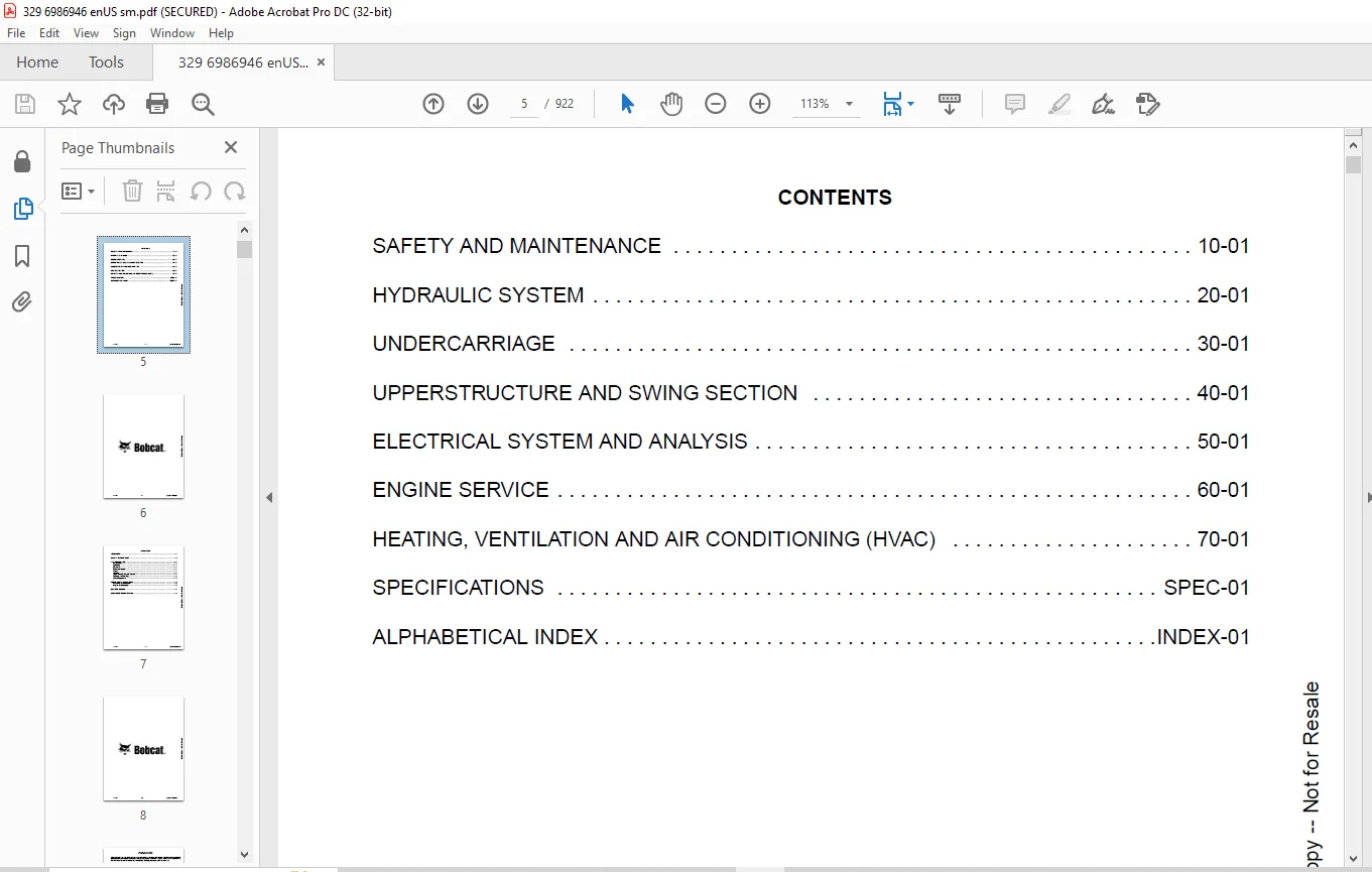
CONTENTS 5
FOREWORD 7
FOREWORD 9
SAFETY INSTRUCTIONS 11
FIRE PREVENTION 13
Maintenance 13
Operation 13
Electrical 13
Hydraulic System 13
Fueling 13
Starting 13
Spark Arrester Exhaust System 13
Welding And Grinding 14
Fire Extinguishers 14
SERIAL NUMBER LOCATIONS 15
Excavator Serial Number 15
Engine Serial Number 15
DELIVERY REPORT 16
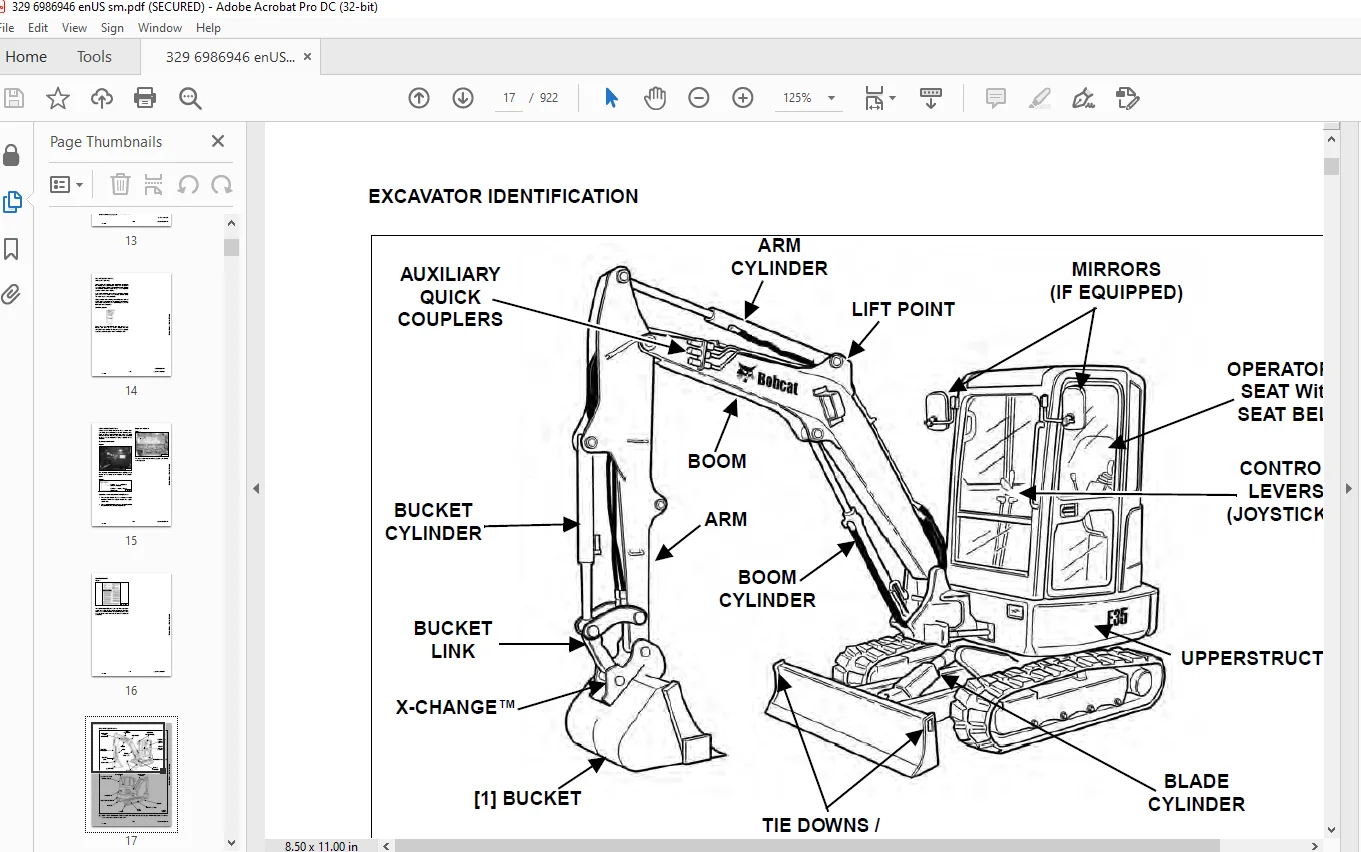
EXCAVATOR IDENTIFICATION 17
SAFETY AND MAINTENANCE 19
LIFTING AND BLOCKING THE EXCAVATOR 23
Procedure 23
UPPERSTRUCTURE SLEW LOCK 25
Operation 25
LIFTING THE EXCAVATOR 27
Procedure 27
OPERATOR CAB (ROPS / TOPS) 29
Description 29
Cab Door 29
Front Window 30
Front Wiper 31
Window Washer Reservoir 31
Right Side Window 32
Heating, Ventilation And Air Conditioning Duct 33
TRANSPORTING THE EXCAVATOR ON A TRAILER 35
Loading And Unloading 35
Fastening 35
TAILGATE 37
Opening And Closing 37
Adjusting The Bumper 37
Adjusting The Latch 37
RIGHT SIDE COVER 39
Opening And Closing 39
Adjusting The Latch 39
SERVICE SCHEDULE 41
Chart 41
AIR CLEANER SERVICE 43
Daily Check 43
Replacing Filter Elements 43
ENGINE COOLING SYSTEM 45
Cleaning 45
Checking Level 45
Removing And Replacing Coolant 46
FUEL SYSTEM 49
Fuel Specifications 49
Biodiesel Blend Fuel 49
Filling The Fuel Tank 50
Fuel Filter 51
Draining The Fuel Tank 51
Removing Air From The Fuel System 52
ENGINE LUBRICATION SYSTEM 53
Checking And Adding Engine Oil 53
Engine Oil Chart 53
Removing And Replacing Oil And Filter 54
HYDRAULIC SYSTEM 55
Checking And Adding Fluid 55
Hydraulic Fluid Chart 56
Removing And Replacing Hydraulic Filters 56
Removing And Replacing Hydraulic Fluid 57
LUBRICATING THE EXCAVATOR 59
Lubrication Locations 59
TRAVEL MOTOR 63
Checking And Adding Oil 63
Removing And Replacing Oil 63
SPARK ARRESTOR MUFFLER 65
Cleaning Procedure 65
ALTERNATOR BELT 67
Belt Adjustment 67
Belt Replacement 67
SEAT BELT 69
Inspection And Maintenance 69
PIVOT PINS 71
Inspection And Maintenance 71
EXCAVATOR STORAGE AND RETURN TO SERVICE 73
Storage 73
Return to Service 73
STOPPING THE ENGINE AND LEAVING THE EXCAVATOR 75
Procedure 75
Emergency Exits 76
MOTION ALARM SYSTEM (IF EQUIPPED) 77
Description 77
Inspecting 77
Adjusting Switch Position 77
REMOTE START TOOL KIT – MEL1563 79
Remote Start Tool – MEL1563 79
Service Tool Harness Communicator – MEL1566 81
REMOTE START TOOL (SERVICE TOOL) KIT – 7003031 83
Description 83
Remote Start Tool (Service Tool) – 7003030 84
Excavator Service Tool Harness – 6689747 85
Computer Service Tool Harness – 6689746 86
TOWING THE EXCAVATOR 87
Procedure 87
HYDRAULIC SYSTEM 89
HYDRAULIC/HYDROSTATIC SCHEMATICS 95
HYDRAULIC SYSTEM INFORMATION 97
Glossary Of Hydraulic / Hydrostatic Symbols 97
Troubleshooting The Hydraulic Circuit 101
Troubleshooting The Cylinder Circuit 102
Troubleshooting The Swing (Upperstructure Slew) Circuit 103
Troubleshooting The Travel Circuit 104
CYLINDER (BOOM) 105
Testing 105
Removal And Installation 107
Parts Identification 109
Disassembly 110
Assembly 112
CYLINDER (ARM) 117
Testing 117
Removal And Installation 119
Parts Identification 121
Disassembly 122
Assembly 124
CYLINDER (BOOM SWING) 129
Testing 129
Removal And Installation 131
Parts Identification 133
Disassembly 134
Assembly 136
CYLINDER (BUCKET) 139
Testing 139
Removal And Installation 141
Parts Identification 143
Disassembly 144
Assembly 146
CYLINDER (BLADE) 149
Testing 149
Removal And Installation 151
Parts Identification 152
Disassembly 153
Assembly 155
CYLINDER (CLAMP) 159
Testing 159
Removal And Installation 160
Parts Identification 161
Disassembly 162
Assembly 165
CYLINDER (ANGLE BLADE) 171
Testing 171
Removal And Installation 172
Parts Identification 174
Disassembly 175
Assembly 177
CYLINDER (EXTENDABLE ARM) 181
Testing 181
Parts Identification 183
Disassembly 184
Assembly 187
VALVE (MAIN RELIEF) 191
Testing And Adjusting The Main Relief Valve 191
VALVES (PORT RELIEF) 197
Testing And Adjusting Port Relief Valve Pressure 197
VALVES (CROSSPORT RELIEF) 199
Testing And Adjusting The Crossport Relief Valves 199
VALVE (PRESSURE REDUCING) 205
Testing And Adjusting The Pressure Reducing Valve 205
VALVE (BOOM LOCK) 207
Removal And Installation 207
VALVE (ARM LOCK) 209
Removal And Installation 209
HYDRAULIC CONTROL VALVE 211
Description 211
Removal And Installation 211
Disassembly 219
Right Travel Valve Section Disassembly And Assembly 221
Boom Swing Valve Section Disassembly And Assembly 226
Boom Valve Section Disassembly And Assembly 233
Left Travel Valve Section Disassembly And Assembly 237
Arm Valve Section Disassembly And Assembly 242
Bucket Valve Section Disassembly And Assembly 246
Auxiliary Valve Section Disassembly And Assembly 250
Boost Valve Section Disassembly And Assembly 254
Blade Valve Section Disassembly And Assembly 258
Slew Valve Section Disassembly And Assembly 263
Assembly 267
HYDRAULIC PUMP 275
Description 275
Torque Adjustment 276
Testing The Piston Pump 277
Testing The Gear Pump 279
Testing Auxiliary Hydraulic Flow 280
Removal And Installation 281
Coupler Removal And Installation 283
Hydraulic Pump Start Up 284
Parts Identification (Gear Pump) 285
Parts Identification (Piston Pump) 286
Disassembly 287
Gear Pump Disassembly 288
Gear Pump Assembly 291
Piston Pump Disassembly 294
Piston Pump Assembly 300
Assembly 306
MANIFOLD ASSEMBLY / ACCUMULATOR 309
Description 309
Removal And Installation 309
Parts Identification 313
Disassembly 314
Assembly 324
MANIFOLD ASSEMBLY / ACCUMULATOR (WITH ANGLE BLADE) 335
Description 335
Removal And Installation 335
Parts Identification 337
Disassembly And Assembly 338
TRAVEL MOTOR 345
Description 345
Removal and installation 345
Parts Identification 347
Disassembly 348
Assembly 358
SWIVEL JOINT 369
Description 369
Removal And Installation 369
Parts Identification 371
Disassembly 372
Assembly 373
SWING MOTOR 377
Description 377
Removal And Installation 377
Parts Identification 380
Disassembly 381
Assembly 386
SWING MOTOR (DRIVE CARRIER) 393
Description 393
Removal And Installation 393
Parts Identification 394
Disassembly 395
Assembly 397
CONTROL PATTERN SELECTOR VALVE 401
Description 401
Removal And Installation 401
Parts Identification 402
Disassembly 403
Assembly 404
RIGHT CONTROL LEVER (JOYSTICK) 405
Description 405
Testing 405
Handle Removal And Installation 406
Removal And Installation 410
Parts Identification 413
Disassembly 414
Assembly 419
LEFT CONTROL LEVER (JOYSTICK) 425
Description 425
Testing 425
Handle Removal And Installation 426
Removal And Installation 429
Parts Identification 431
Disassembly 432
Assembly 437
FILTER (HYDRAULIC) 443
Description 443
Housing Removal And Installation 443
FILTER (CASE DRAIN) 445
Description 445
Housing Removal And Installation 445
HYDRAULIC RESERVOIR 447
Description 447
Removal And Installation 447
OIL COOLER 449
Description 449
Removal And Installation 449
DIRECT TO TANK VALVE 451
Description 451
Removal And Installation 451
Parts Identification 452
Disassembly And Assembly 453
BUILDUP VALVE 455
Description 455
Removal And Installation 455
Parts Identification 456
Disassembly And Assembly 457
BLADE CONTROL LEVER 459
Handle Removal And Installation 459
Removal And Installation 461
Parts Identification 463
Disassembly And Assembly 464
CASE DRAIN FILTER MOUNT 469
Removal And Installation 469
TRAVEL CONTROL VALVE 471
Removal And Installation 471
Parts Identification 472
Disassembly And Assembly 473
REMOVING AIR FROM THE HYDRAULIC SYSTEM 479
Procedure 479
HYDRAULIC X-CHANGE MANIFOLD 481
Removal And Installation 481
Parts Identification 482
Disassembly And Assembly 483
SECONDARY AUXILIARY VALVE 487
Removal And Installation 487
Parts Identification 489
Disassembly And Assembly 490
UNDERCARRIAGE 497
BLADE 499
Description 499
Removal And Installation 499
BLADE (ANGLE) 501
Removal And Installation 501
TRACK FRAME COMPONENTS 503
Description 503
Track Lug Height 503
Checking Tension 504
Adjusting Tension 505
Rubber Track Removal And Installation 507
Steel Track Removal And Installation 510
Idler (Front) Removal And Installation 513
Idler (Front) Parts Identification 514
Idler (Front) Disassembly 515
Idler (Front) Assembly 517
Coil Spring Assembly And Cylinder Disassembly And Assembly (W/o Replaceable Shaft) 520
Coil Spring Cylinder Parts Identification (W/ Replaceable Shaft) 521
Coil Spring Assembly And Cylinder Disassembly And Assembly (With Replaceable Shaft) 522
Roller Removal and Installation 524
Roller Parts Identification 525
Roller Disassembly 526
Roller Assembly 528
Track Guide Removal And Installation 530
Sprocket Removal And Installation 530
Track Damage Identification 531
SWING CIRCLE GEAR 541
Removal And Installation 541
UPPERSTRUCTURE AND SWING SECTION 543
UPPERSTRUCTURE 547
Description 547
Removal 547
Installation 549
CANOPY 553
Removal And Installation 553
CAB 557
Removal And Installation 557
Door Removal And Installation 562
Front Window Removal And Installation 563
Right Side Rear Sliding Window Removal And Installation 566
Right Side Front Sliding Window Removal And Installation 566
Glass Removal 567
Right Side Front And Rear Sliding Window Weather Strip Removal And Installation 568
Right Side Front And Rear Sliding Window Wiper Strip Removal And Installation 568
Glass Installation 569
SEAT AND SEAT MOUNT 575
Seat Mount Removal And Installation 575
Seat Removal And Installation 576
RIGHT CONSOLE 577
Description 577
Console Cover Removal And Installation 577
Console Frame Removal And Installation 578
LEFT CONSOLE 581
Description 581
Joystick Console Cover (Bottom) Removal And Installation 581
Joystick Console Cover (Top) Removal And Installation 582
Compression Spring Removal And Installation 583
Compression Spring Disassembly And Assembly 583
Lever Removal And Installation 585
Joystick Console Frame Removal And Installation 586
Joystick Console Frame Disassembly And Installation 587
Left Rear Console Cover Removal And Installation 588
Left Rear Console Frame Removal And Installation 589
Left Rear Console Frame Disassembly And Assembly 592
BLADE CONTROL 593
Removal And Installation 593
Disassembly And Assembly 593
Linkage Removal And Installation 594
Linkage Disassembly And Assembly 596
UPPERSTRUCTURE SLEW LOCK 599
Removal And Installation 599
Disassembly And Assembly 599
FLOOR MAT AND FLOOR PANEL 601
Description 601
Removal And Installation 601
BOOM SWING PEDAL 605
Description 605
Removal And Installation 605
Disassembly And Assembly 605
Linkage Removal And Installation 607
TRAVEL LEVERS / PEDALS 609
Description 609
Adjustment 609
Removal And Installation 612
Disassembly And Assembly 612
FUEL TANK 615
Removal And Installation 615
HORN 619
Removal And Installation 619
SWING FRAME 621
Description 621
Removal And Installation 621
Hose Routing 625
Bushing Removal And Installation 626
Swing Frame Bushing Removal And Installation 626
BOOM 629
Description 629
Removal And Installation 629
ARM 631
Description 631
Removal And Installation 631
Arm To Boom Bushing Removal And Installation 632
Arm To Bucket And Bucket Link Bushing Removal And Installation 633
ARM (EXTENDABLE) 635
Removal And Installation 635
Arm To Boom Bushing Removal And Installation 636
Arm To Bucket Bushing Removal And Installation 637
Disassembly And Assembly 638
Shimming Procedure 646
BUCKET 647
Removal And Installation (Pin-On X-Change) 647
Removal And Installation (Bolt-On X-Change) 653
Removal And Installation (Pin-On Attachment) 659
Bucket Teeth Removal And Installation 660
Bucket Side Cutting Edge Removal And Installation 661
TAILGATE 663
Removal And Installation 663
Latch Removal And Installation 664
X-CHANGE 665
Pin-On Removal And Installation 665
Pin-On Disassembly and Assembly 666
X-CHANGE (HYDRAULIC) 667
Removal And Installation 667
Parts Identification 669
Disassembly 670
Assembly 675
RIGHT SIDE COVER 683
Removal And Installation 683
QUICK COUPLER (KLAC™ SYSTEM) 685
Troubleshooting 685
Daily Inspection 685
Removal And Installation 686
Parts Identification 688
Disassembly 689
Assembly 690
QUICK COUPLER (LEHNHOFF® SYSTEM) 693
Troubleshooting 693
Daily Inspection 693
Removal (MS03 And MS08) 694
Installation (MS03 And MS08) 695
Parts Identification (MS03) 696
Disassembly And Assembly (MS03) 697
Parts Identification (MS08) 698
Disassembly (MS08) 699
Assembly (MS08) 702
TOOL BOX 707
Removal And Installation 707
ELECTRICAL SYSTEM AND ANALYSIS 709
ELECTRICAL SCHEMATICS 711
ELECTRICAL SYSTEM INFORMATION 713
Glossary Of Electrical Symbols 713
Harness Connectors 716
Troubleshooting 718
Description 719
Fuse And Relay Locations / Identification 719
BATTERY 721
Removal And Installation 721
Servicing 722
Using A Booster Battery (Jump Starting) 723
ALTERNATOR 725
Belt Adjustment 725
Belt Replacement 725
Charging System Inspection 726
Description 727
Tests 727
Alternator Output Test 728
Full Field Test 728
Alternator Regulator Test 729
Alternator Regulator Test With Voltmeter 729
Removal And Installation 730
Parts Identification 731
STARTER 733
Testing 733
Removal And Installation 734
Parts Identification 735
LIGHTS 737
Upperstructure Light Removal And Installation 737
Upperstructure Light Disassembly And Assembly 737
Boom Light Removal And Installation 738
Boom Light Bulb Replacement 738
MAGNETIC LOCKOUT SENSOR 739
Testing Left Console Magnetic Lockout Sensor 739
Left Console Magnetic Lockout Sensor Removal And Installation 740
FUEL LEVEL SENDER 743
Removal And Installation 743
Testing 744
DIAGNOSTICS SERVICE CODES 745
Description 745
Service Codes List 746
CONTROL PANEL SETUP 747
Panel Setup (Deluxe Instrument Panel) 747
Password Setup (Keyless Start Panel) 753
Password Setup (Deluxe Instrument Panel) 755
Maintenance Clock 758
INSTRUMENT PANEL 763
Removal And Installation 763
CONTROLLER 765
Description 765
Gateway Controller Removal and Installation 765
Auxiliary Controller Removal And Installation 767
KEY SWITCH 769
Removal And Installation 769
WIPER MOTOR 771
Removal And Installation 771
MOTION ALARM SYSTEM 773
Description 773
Inspecting 773
Adjusting Switch Position 774
SERVICE PC (LAPTOP COMPUTER) 775
Connecting The Remote Start Tool 775
Connecting Remote Start Tool (Service Tool) 775
SHUT-OFF SWITCH 777
Description 777
Removal And Installation 778
TRAVEL MOTOR AUTO-SHIFT 781
Auto-Shift Drive System (If Equipped) 781
Troubleshooting 782
ENGINE SERVICE 785
ENGINE INFORMATION 787
Description 787
Specifications 788
Torque Values 792
Troubleshooting 793
Removal And Installation 794
Engine Mount Replacement 800
Compression – Checking 801
ENGINE SPEED CONTROL 803
Removal And Installation 803
SPARK ARRESTOR MUFFLER 805
Removal And Installation 805
AIR CLEANER 807
Removal And Installation 807
ENGINE COOLING SYSTEM 809
Radiator Removal And Installation 809
Water Pump Removal And Installation 810
Water Pump Disassembly And Assembly 811
Thermostat Housing Removal And Installation 812
Testing The Thermostat 813
LUBRICATION SYSTEM 815
Oil Pan Removal And Installation 815
Oil Pump Removal And Installation 815
Oil Pump Inspection 816
Engine Oil Pressure – Testing 817
FUEL SYSTEM 819
Fuel Camshaft Removal And Installation 819
Fuel Camshaft Governor Disassembly And Assembly 820
Fuel Shutoff Solenoid – Checking 821
Fuel Shutoff Solenoid Removal And Installation 821
Fuel Injection Pump Removal And Installation 822
Injection Pump – Timing 824
Fuel Injector Removal And Installation 826
Fuel Injector Nozzle Pressure – Checking 828
Nozzle Spray Condition 829
Valve Seat Tightness 829
CYLINDER HEAD 831
Glow Plug – Testing 831
Glow Plug Removal And Installation 832
Valve Clearance Adjustment 832
Valve Timing – Checking 833
Cylinder Head Removal And Installation 834
Cylinder Head Disassembly and Assembly 837
Cylinder Head – Servicing 837
Cylinder Head Top Clearance 838
Valve Guide – Checking 838
Reconditioning The Valve And Valve Seat 839
Valve Spring 841
Valve Tappets 842
Rocker Arm And Shaft – Checking 842
CRANKSHAFT AND PISTONS 843
Piston And Connecting Rod Removal And Installation 843
Piston And Connecting Rod – Servicing 845
Cylinder Bore Checking 847
Connecting Rod Alignment 848
Crankshaft And Bearings Removal And Installation 848
Crankshaft And Bearings – Servicing 850
CAMSHAFT AND TIMING GEARS 855
Timing Gearcase Cover Removal And Installation 855
Timing Gears Backlash – Checking 857
Idler Gear And Shaft Removal And Installation 858
Camshaft – Servicing 859
Idler Gear And Shaft Servicing 860
FLYWHEEL AND HOUSING 861
Flywheel Housing Removal And Installation 861
Hydraulic Pump Coupler Removal And Installation 862
Flywheel Removal And Installation 863
Rear End Plate Removal And Installation 863
HEATING, VENTILATION AND AIR CONDITIONING (HVAC) 865
HEATER SYSTEM 867
Description 867
Components 867
REGULAR MAINTENANCE 869
Filter Element Removal And Installation 869
Heater Coil 870
TROUBLESHOOTING 871
Blower Motor Does Not Operate 871
Blower Motor Operates Normally, But Air Flow Is Insufficient 871
Electrical System 872
HEATER UNIT 877
Removal And Installation 877
HEATER COIL 879
Removal And Installation 879
BLOWER FAN 881
Removal And Installation 881
HEATER VALVE 883
Removal And Installation 883
EVAPORATOR / HEATER UNIT 885
Removal And Installation 885
THERMOSTAT 887
Description 887
Removal And Installation 888
EXPANSION VALVE 891
Removal And Installation 891
EVAPORATOR COIL 893
Removal And Installation 893
HVAC DUCT 895
Removal And Installation 895
SPECIFICATIONS 897
329 EXCAVATOR SPECIFICATIONS 899
Dimensions 899
Performance 901
Controls 901
Engine 901
Hydraulic System 902
Hydraulic Cylinders 902
Hydraulic Cycle Times 902
Electrical 903
Drive System 903
Slew System 903
Undercarriage 903
Capacities 903
Tracks 903
Ground Pressure 903
TORQUE SPECIFICATIONS FOR BOLTS 905
Torque For General SAE Bolts 905
Torque For General Metric Bolts 906
HYDRAULIC CONNECTION SPECIFICATIONS 907
O-Ring Face Seal Connection 907
Straight Thread O-Ring Fitting 908
Tubelines And Hoses 908
Flare Fitting 909
Port Seal Fitting 910
HYDRAULIC FLUID SPECIFICATIONS 911
Specifications 911
CONVERSIONS 913
Decimal And Millimeter Equivalents 913
U S To Metric Conversion Chart 913
SERVICE TOOLS REQUIRED 915
Remote Start Tools 915
Hydraulic Tools 916
Engine Tools 918
HVAC Tools 920
ALPHABETICAL INDEX 921
IMAGES PREVIEW OF THE MANUAL:
Questions? Email us: [email protected]
https://vimeo.com/841097451?share=copy
PLEASE NOTE:
- This is the SAME exact manual used by your dealers to fix your vehicle.
- The same can be yours in the next 2-3 mins as you will be directed to the download page immediately after paying for the manual.
- Any queries / doubts regarding your purchase, please feel free to contact [email protected]
s.m