Bobcat 331 331E 334 Service Manual – PDF DOWNLOAD
$34.95
Bobcat 331 331E 334 Service Manual – PDF DOWNLOAD
S/N 232511001 & Above
S/N 232711001 & Above
S/N 232611001 & Above
(D Series)
Description
Bobcat 331 331E 334 Service Manual – PDF DOWNLOAD
FILE DETAILS:
Bobcat 331 331E 334 Service Manual – PDF DOWNLOAD
Language : English
Pages : 872
Downloadable : Yes
File Type : PDF
Size:28.5 MB
DESCRIPTION:
Bobcat 331 331E 334 Service Manual – PDF DOWNLOAD
FOREWORD
This manual is for the Bobcat Hydraulic excavator mechanic. It provides necessary servicing and adjustment procedures for the hydraulic excavator and its component parts and systems. Refer to the Operation & Maintenance Manual for operating instructions, starting procedure, daily checks, etc.
SAFETY INSTRUCTIONS
Instructions are necessary before operating or servicing machine. Read and understand the Operation & Maintenance Manual, Operator’s Handbook and signs (decals) on machine. Follow warnings and instructions in the manuals when making repairs, adjustments or servicing. Check for correct function after adjustments, repairs or service. Untrained operators and failure to follow instructions can cause injury or death.
The following publications provide information on the safe use and maintenance of the Bobcat machine and attachments:
TABLE OF CONTENTS:
Bobcat 331 331E 334 Service Manual – PDF DOWNLOAD
MAINTENANCE SAFETY 3
ALPHABETICAL INDEX 5
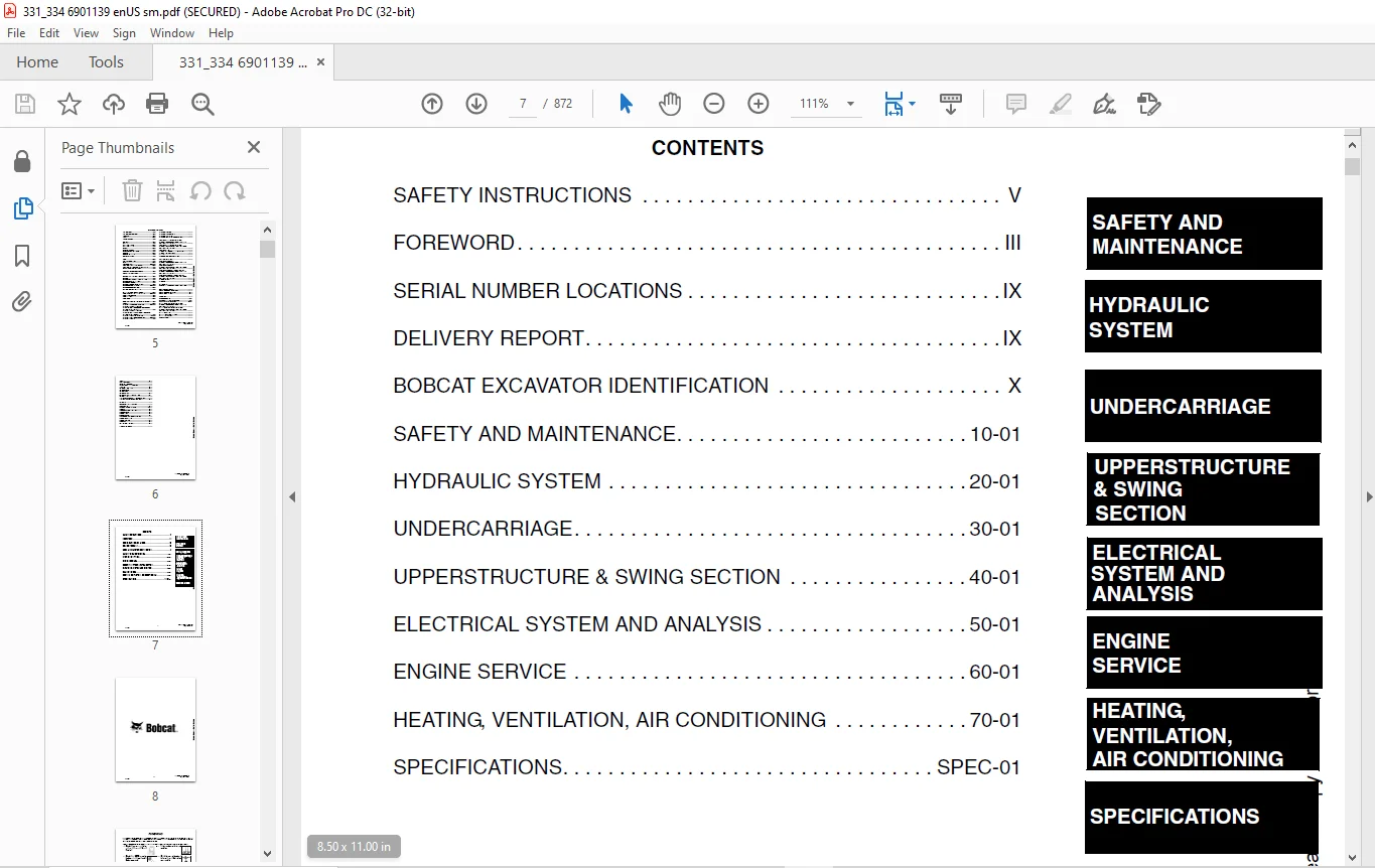
CONTENTS 7
FOREWORD 9
SAFETY INSTRUCTIONS 11
Fire Prevention 13
SERIAL NUMBER LOCATIONS 15
Bobcat Excavator Serial Number 15
Engine Serial Number 15
DELIVERY REPORT 15
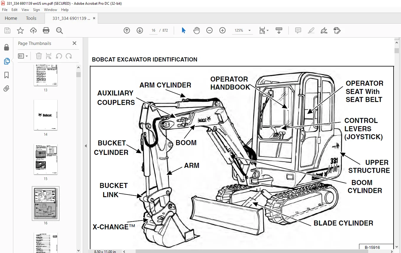
BOBCAT EXCAVATOR IDENTIFICATION 16
SAFETY AND MAINTENANCE 17
LIFTING AND BLOCKING THE EXCAVATOR 19
Procedure 19
SWING LOCK 21
Operation 21
LIFTING THE EXCAVATOR 23
Procedure 23
OPERATOR CAB (ROPS/TOPS) (IF EQUIPPED) 25
Emergency Exit 25
Cab Door 25
Front Window 25
TRANSPORTING THE EXCAVATOR 27
Procedure 27
TAILGATE 29
Opening And Closing The Tailgate (Early Models) 29
Adjusting The Bumper 29
Adjusting The Tailgate Latch (Early Models) 30
Opening And Closing The Tailgate (Later Models) 30
Adjusting The Tailgate Latch (Later Models) 31
SERVICE SCHEDULE 33
Chart 33
AIR CLEANER SERVICE 35
Daily Check 35
Replacing The Filters 35
HEATER AIR FILTERS (WITH CAB OPTION ONLY) 37
Recirculation Filter 37
Fresh Air Filter 37
ENGINE COOLING SYSTEM 39
Cleaning The Cooling System 39
Checking The Coolant Level 39
Replacing The Coolant 40
FUEL SYSTEM 43
Fuel Specification 43
Filling The Fuel Tank 43
Removing Water From The Fuel Filter 44
Replacing The Fuel Filter 44
Removing Air From The Fuel System 45
Draining The Fuel Tank 45
ENGINE LUBRICATION SYSTEM 47
HYDRAULIC SYSTEM 49
Checking And Adding Fluid 49
Replacing The Hydraulic Filter 50
Replacing The Case Drain Filter 50
Replacing The Hydraulic Fluid 51
Diagnostic Couplers 52
LUBRICATING THE EXCAVATOR 53
Procedure 53
TRAVEL MOTOR 55
Checking Oil Level 55
Draining The Travel Motor 55
SPARK ARRESTOR MUFFLER 57
Cleaning The Spark Arrestor Muffler 57
Continued On Next Page 59
Continued On Next Page 60
Continued On Next Page 61
Continued On Next Page 62
Continued On Next Page 63
HYDRAULIC SYSTEM 59
HYDRAULIC/HYDROSTATIC SCHEMATICS 65
HYDRAULIC SYSTEM INFORMATION 73
Glossary Of Hydraulic/Hydrostatic Symbols For Excavators 73
Troubleshooting The Hydraulic Circuit 77
Troubleshooting The Cylinder Circuit 78
Troubleshooting The Swing (Slew) Circuit 79
Troubleshooting The Travel Circuit 80
BOOM CYLINDER 81
Checking The Boom Cylinder 81
Removal And Installation 83
Parts Identification 85
Disassembly 86
Assembly 87
ARM CYLINDER 91
Checking The Arm Cylinder 91
Removal And Installation 93
Parts Identification 94
Disassembly 95
Assembly 97
BOOM OFFSET CYLINDER 101
Checking The Boom Offset Cylinder 101
Removal And Installation 103
Parts Identification 104
Disassembly 105
Assembly 107
BUCKET CYLINDER 111
Checking The Bucket Cylinder 111
Removal And Installation (Standard And Long Arm) 113
Removal And Installation (Extendible Arm) 114
Parts Identification 117
Disassembly 118
Assembly 120
BLADE CYLINDER 123
Checking The Blade Cylinder 123
Removal And Installation 125
Parts Identification 126
Disassembly 127
Assembly 129
EXTENDIBLE ARM CYLINDER 133
Removal And Installation 133
Parts Identification 134
MAIN RELIEF VALVES 135
Testing And Adjusting The Main Relief Valves (S/N 232512782 & Below, 232711433 & Below And 232612157 & Below) 135
System Pressures At Gauge Port Specifications (S/N 232512782 & Below, 232711433 & Below And 232612157 & Below) 135
Testing And Adjusting The Main Relief Valves (S/N 232512783 & Above, 232711434 & Above And 232612158 & Above) 139
System Pressures At Gauge Port Specifications (S/N 232512783 & Above, 232711434 & Above And 232612158 & Above) 139
PORT RELIEF VALVES 143
Testing And Adjusting Port Relief Valve Pressure (S/ N 232512782 & Below, 232711433 & Below And 232612157 & Below) 143
Testing And Adjusting Port Relief Valve Pressure (S/ N 232512783 & Above, 232711434 & Above And 232612158 & Above) 144
CROSSPORT RELIEF VALVES 147
Testing The Crossport Relief Valves 147
System Pressures At Gauge Port Specifications 147
PRESSURE REDUCING VALVE 149
Testing And Adjusting The Pressure Reducing Valve (S/N 232512782 & Below, 232711433 & Below And 232612157 & Below) 149
Testing And Adjusting The Pressure Reducing Valve (S/N 232512783 & Above, 232711434 & Above And 232612158 & Above) 151
HYDRAULIC CONTROL VALVE (S/N 232512782 & BELOW, 232711433 & BELOW AND 232612157 & BELOW) 153
Description 153
Removal And Installation 153
Control Valve Identification 157
Disassembly 158
Right Travel Valve Section Disassembly And Assembly 159
Boom Offset Valve Section Disassembly And Assembly 162
Boom Valve Section Disassembly And Assembly 165
Left Travel Valve Section Disassembly And Assembly 168
Arm Valve Section Disassembly And Assembly 170
Bucket Valve Section Disassembly And Assembly 173
Auxiliary Valve Section Disassembly And Assembly 175
Boost Valve Section Disassembly And Assembly 178
Blade Valve Section Disassembly And Assembly 180
Swing Valve Section Disassembly And Assembly 183
Assembly 185
HYDRAULIC CONTROL VALVE (S/N 232512783 & ABOVE, 232711434 & ABOVE AND 232612158 & ABOVE) 191
Description 191
Removal And Installation 191
Control Valve Identification 197
Disassembly 198
Right Travel Valve Section Disassembly And Assembly 199
Boom Offset Valve Section Disassembly And Assembly 204
Boom Valve Section Disassembly And Assembly 210
Left Travel Valve Section Disassembly And Assembly 214
Arm Valve Section Disassembly And Assembly 219
Bucket Valve Section Disassembly And Assembly 223
Auxiliary Valve Section Disassembly And Assembly 226
Boost Valve Section Disassembly And Assembly 230
Blade Valve Section Disassembly And Assembly 234
Swing Valve Section Disassembly And Assembly 238
Assembly 242
HYDRAULIC PUMP 249
Description 249
Torque Adjustment 249
Testing The Piston Pump 250
Testing The Gear Pump 252
Testing Auxiliary Hydraulic Flow 253
Removal And Installation 254
Coupler Removal And Installation 256
Parts Identification 257
Piston Pump Parts Identification 258
Disassembly 259
Gear Pump Disassembly 260
Gear Pump Assembly 263
Piston Pump Disassembly 266
Piston Pump Assembly 273
Assembly 282
MANIFOLD ASSEMBLY/ACCUMULATOR (S/N 232512162 & BELOW, 232611711 & BELOW AND 232711316 & BELOW) 283
Manifold Description 283
Removal And Installation 283
MANIFOLD ASSEMBLY (S/N 232512162 & BELOW, 232611711 & BELOW AND 232711316 & BELOW) 287
Parts Identification 287
Disassembly 288
Assembly 296
MANIFOLD ASSEMBLY/ ACCUMULATOR (S/N 232512163 & ABOVE, 232611712 & ABOVE AND 232711317 & ABOVE) 305
Manifold Description 305
Removal And Installation 305
MANIFOLD ASSEMBLY (S/N 232512163 & ABOVE, 232611712 & ABOVE AND 232711317 & ABOVE) 309
Parts Identification 309
Disassembly 310
Assembly 320
TRAVEL MOTOR 331
Removal And Installation 331
Parts Identification 333
Disassembly 334
Assembly 343
SWIVEL JOINT 355
Removal And Installation 355
Parts Identification 356
Description 357
Disassembly 357
Assembly 358
SWING MOTOR 361
Removal And Installation 361
Parts Identification 367
Disassembly 368
Assembly 370
Cross Port Relief Valve Parts Identification 375
Cross Port Relief Valve Disassembly 376
Cross Port Relief Valve Assembly 378
SWING MOTOR DRIVE CARRIER 381
Removal And Installation 381
Parts Identification 382
Disassembly 383
Assembly 385
CONTROL PATTERN SELECTOR VALVE 389
Removal And Installation 389
Parts Identification 389
Disassembly 390
Assembly 391
RIGHT CONTROL LEVER (JOYSTICK) (S/N 232512782 & BELOW, 232711433 & BELOW AND 232612157 & BELOW) 393
Testing 393
Handle Removal And Installation 394
Joystick Assembly, Removal And Installation 398
Parts Identification 401
Disassembly 402
LEFT CONTROL LEVER (JOYSTICK) (S/N 232512782 & BELOW, 232711433 & BELOW AND 232612157 & BELOW) 407
Testing 407
Handle Removal And Installation 408
Joystick Assembly, Removal And Installation 411
Parts Identification 415
Disassembly And Assembly 416
LEFT CONTROL LEVER (JOYSTICK) (S/N 232512783 & ABOVE, 232711434 & ABOVE AND 232612518 & ABOVE) 421
Testing 421
Handle Removal And Installation 422
Joystick Assembly, Removal And Installation 425
Parts Identification 428
Disassembly 429
Assembly 433
RIGHT CONTROL LEVER (JOYSTICK) (S/N 232512783 & ABOVE, 2327114334 & ABOVE AND 232612518 & ABOVE) 439
Testing 439
Handle Removal And Installation 440
Joystick Assembly Removal And Installation 444
Parts Identification 446
Disassembly 447
Assembly 451
HYDRAULIC FILTER 457
Removal And Installation 457
HYDRAULIC RESERVOIR 459
Removal And Installation 459
OIL COOLER 461
Removal And Installation 461
DIRECT TO TANK VALVE 465
Removal And Installation 465
Disassembly And Assembly 466
BUILD UP VALVE 467
Description 467
Removal And Installation 467
Disassembly And Assembly 467
CASE DRAIN FILTER 469
Removal And Installation 469
Continued On Next Page 471
UNDERCARRIAGE 471
BLADE 473
Removal And Installation 473
TRACKS 475
Track Lug Height 475
Adjustment 475
Rubber Track Removal And Installation 478
Steel Track Removal And Installation 480
TRACK FRAME 483
Disassembly And Assembly 483
Recoil Spring Disassembly And Assembly 485
TRACK DAMAGE IDENTIFICATIONS 487
Cutting Of Steel Cords 487
Abrasion Of Embedded Metals 488
Separation Of Embedded Metals 489
Separation Of Embedded Metals Due To Corrosion 490
Cuts On The Lug Side Rubber 491
Cracks On The Lug Side Rubber Due To Fatigue 492
Lug Abrasion 493
Cracks And Cuts On The Lug Side Rubber 494
Abrasion Of The Track Roller Side 495
Cuts On The Edges Of Track Roller Side 496
TRACK IDLER 499
Parts Identification (S/N 232511877 & Below, 23271165 & Below And 232611488 & Below) 499
Disassembly (S/N 232511877 & Below, 232711165 & Below And 232611488 & Below) 500
Assembly (S/N 232511877 & Below, 232711165 & Below And 232611488 & Below) 502
Parts Identification (S/N 232511878 & Above, 23271166 & Above And 232611489 & Above) 506
Disassembly (S/N 232511878 & Above, 232711166 & Above And 232611489 & Above) 507
Assembly (S/N 232511878 & Above, 232711166 & Above And 232611489 & Above) 509
TRACK ROLLER 513
Parts Identification (S/N 232511877 & Below, 232711165 & Below And 232611488 & Below) 513
Disassembly (S/N 232511877 & Below, 23271165 & Below And 232611488 & Below) 514
Assembly (S/N 232511877 & Below, 23271165 & Below And 232611488 & Below) 516
Parts Identification (S/N 232511878 & Above, 232711166 & Above And 232611489 & Above) 520
Disassembly (S/N 232511878 & Above, 23271166 & Above And 232611489 & Above) 521
Assembly (S/N 232511878 & Above, 23271166 & Above And 232611489 & Above) 522
SWING CIRCLE GEAR 525
Removal And Installation 525
Swing Bearing Removal 527
Swing Bearing Installation 528
Alignment Pins (Not Threaded) 530
Continued On Next Page 531
Continued On Next Page 532
UPPERSTRUCTURE & SWING SECTION 531
UPPERSTRUCTURE 535
Removal And Installation 535
Swing Bearing Removal 537
Swing Bearing Installation 538
Alignment Pins (Not Threaded) 540
ROPS CANOPY 543
Removal And Installation 543
CAB 547
Removal And Installation 547
Door Removal And Installation 550
Front Window Removal And Installation 551
Lower Front Window Removal And Installation 553
Right Side Rear Sliding Window Removal And Installation 554
Right Side Front Sliding Window Removal And Installation 555
Right Side Panel And Window Assembly Removal And Installation 556
Door, Left Side, Rear And Upper Front Window Removal And Installation 559
SEAT AND MOUNT 561
Removal And Installation 561
RIGHT CONSOLE 563
Console Cover Removal And Installation 563
Console Base Removal And Installation 564
LEFT CONSOLE 569
Lower Console Cover Removal And Installation 569
Upper Console Cover Removal And Installation 571
Compression Spring Removal And Installation 572
Lock Lever Removal And Installation 573
Upper Console Removal And Installation 574
Console Switch Removal And Installation 576
Disassembly And Assembly 577
Console Base Removal And Installation 579
ENGINE SPEED CONTROL 581
Removal And Installation 581
BLADE CONTROL 583
Lever Removal And Installation 583
Linkage Removal And Installation 584
Linkage Bar Removal And Installation 586
Lower Linkage Removal And Installation 587
RIGHT PEDAL AND LINKAGE 591
Pedal Removal And Installation 591
Right Pedal Disassembly And Assembly 592
TRAVEL CONTROLS 595
Removal And Installation 595
Disassembly And Assembly 596
FLOOR MAT AND FLOOR PANELS 601
Removal And Installation 601
FUEL TANK 603
Removal And Installation 603
HORN 609
Removal And Installation 609
SWING FRAME 611
Boom Swing Bracket Removal And Installation 611
Boom Swing Bracket Hose Installation 615
Bushing Removal 616
Bushing Installation 617
BOOM 619
Removal And Installation 619
Boom Bushing Removal And Installation 620
ARM 621
Removal And Installation 621
Arm To Boom Bushing Removal And Installation 621
Arm To Bucket And Bucket Link Bushing Removal And Installation 622
EXTENDIBLE ARM 623
Removal And Installation 623
Disassembly And Assembly 626
BUCKET 627
Bucket Teeth Removal And Installation 627
Bucket Side Cutting Edge Removal And Installation 628
TAILGATE 629
Removal And Installation 629
Release Rod Removal And Installation (Early Models) 630
Latch Removal And Installation (Early Models) 631
Latch Removal And Installation (Later Models) 631
X-CHANGE™ 633
Removal And Installation 633
Disassembly 635
Assembly 640
RIGHT SIDE COVER 647
Removal And Installation 647
ELECTRICAL SYSTEM AND ANALYSIS 649
ELECTRICAL SCHEMATICS 651
ELECTRICAL SYSTEM INFORMATION 653
Troubleshooting Chart 653
Description 654
Fuse Location 654
BATTERY 655
Servicing 655
Removal And Installation 656
Using A Booster Battery (Jump Starting) 657
ALTERNATOR 659
Adjusting The Alternator Belt 659
Removal And Installation 660
Alternator Identification 662
Charging System Check 663
Alternator Voltage Test 664
Low Voltage Test 664
High Voltage Test 665
Rectifier Continuity (Diode) Test 666
Alternator Regulator Test 667
Disassembly 668
Stator Continuity Test 668
Stator Ground Test 669
Rotor Continuity Test 669
Rotor Ground Test 670
Assembly 670
STARTER 671
Removal And Installation 671
Parts Identification 672
Disassembly 673
Inspection And Repair 678
Assembly 681
LIGHTS 687
Removal And Installation 687
Disassembly And Assembly 688
FUEL LEVEL SENDER 689
Removal And Installation 689
Testing 689
DIAGNOSTICS SERVICE CODE 691
Number Codes List 691
Continued On Next Page 693
ENGINE SERVICE 693
TROUBLESHOOTING 695
Chart 695
SPARK ARRESTOR MUFFLER 697
Removal And Installation 697
AIR CLEANER 699
Removal And Installation 699
RADIATOR 701
Removal And Installation 701
ENGINE COMPONENTS AND TESTING 705
Valve Clearance Adjustment 705
Engine Compression Checking 705
Fuel Shutoff Solenoid Adjustment 707
Fuel Shutoff Solenoid Removal And Installation 707
Fuel Injection Pump Check 708
Fuel Injection Pump Removal And Installation 708
Fuel Injection Pump Timing 710
Fuel Injector Nozzles 711
Fuel Injector Nozzles Removal And Installation 712
Fuel Injector Nozzles Check 713
ENGINE 715
Removal And Installation 715
ENGINE FLYWHEEL 723
Removal And Installation 723
Flywheel Ring Gear 724
RECONDITIONING THE ENGINE 725
Cylinder Head Removal And Installation 725
Cylinder Head Disassembly And Assembly 726
Cylinder Head Servicing 727
Cylinder Head Top Clearance 728
Valve Guide Checking 728
Reconditioning The Valve And Valve Seat 730
Valve Spring 731
Rocker Arm And Shaft Checking 731
Timing Gearcase Cover Removal And Installation 732
Idler Gear And Camshaft Removal And Installation 734
Camshaft Servicing 735
Idler Gear And Shaft Servicing 736
Timing Gears Checking Backlash 737
Fuel Camshaft Removal And Installation 737
Fuel Camshaft Governor 738
Crankshaft Gear Removal And Installation 738
Oil Pump Removal And Installation 739
Oil Pump Service 739
Checking Engine Oil Pressure 740
Oil Pump Relief Valve 741
Piston And Connecting Rod Removal And Installation 741
Piston And Connecting Rod Servicing 743
Connecting Rod Alignment 745
Crankshaft And Bearings Removal And Installation 746
Crankshaft And Bearings, Servicing 748
Cylinder Bore, Checking 751
Water Pump Removal And Installation 751
Water Pump Disassembly And Assembly 752
Fan Removal And Installation 752
Continued On Next Page 755
HEATING, VENTILATION, AIR CONDITIONING 755
HEATER COIL 757
Removal And Installation With A/C 757
Removal And Installation Without A/C 758
HEATER/AC FAN 761
Removal And Installation 761
Disassembly And Assembly 762
Resistor Removal and Installation 763
Wire Connector Removal and Installation 764
HEATER VALVE 767
Removal and Installation 767
AIR CONDITIONING SYSTEM FLOW 770
Principals 770
Chart 771
COMPONENTS 773
Identification 773
SAFETY 777
Safety Equipment 777
REGULAR MAINTENANCE 779
Filter Elements Removal And Installation 779
Compressor Drive Belt Inspection 780
Cleaning The Condenser 780
BASIC TROUBLESHOOTING 783
Poor A/C Performance 783
Cleaning The A/C Evaporator Coil & Heater Coil 784
Compressor Drive Belt Inspection: 785
Checking The Electrical System 786
Engine Coolant By-Passing The Heater Valve 794
GENERAL AIR CONDITIONING SERVICE GUIDELINES 795
Compressor Oil 795
Compressor Oil Check 795
Component Replacement And Refrigeration Leaks 797
SYSTEM TROUBLESHOOTING CHART 799
Blower Motor Does Not Operate 799
Blower Motor Operates Normally, But Air Flow Is Insufficient 799
Insufficient Cooling Although Air Flow And Compressor Operation Are Normal 799
The Compressor Does Not Operate At All, Or Operates Improperly 799
Gauge Pressure Related Troubleshooting 800
TEMPERATURE/PRESSURE 801
Chart 801
AIR CONDITIONING SERVICE 803
Chart 803
SYSTEM CHARGING AND RECLAMATION 805
Reclamation Procedure 805
Charging Procedure With A Manifold Gauge Set 807
Charging Procedure 809
COMPRESSOR 811
Removal And Installation 811
Compressor Clutch Disassembly 813
CONDENSER 817
Removal And Installation 817
RECEIVER/DRIER 819
Removal And Installation 819
PRESSURE RELIEF VALVE 821
Removal And Installation 821
PRESSURE SWITCH 823
Removal And Installation 823
EVAPORATOR/HEATER UNIT 825
Removal And Installation 825
Disassembly And Assembly 826
THERMOSTAT 827
Removal And Installation 827
EXPANSION VALVE 829
Removal And Installation 829
EVAPORATOR 831
Removal And Installation 831
Continued On Next Page 833
SPECIFICATIONS 833
HYDRAULIC EXCAVATOR SPECIFICATIONS 835
Machine Dimensions (Standard Arm) 835
Machine Dimensions (331E Extendible Arm) 836
Machine Dimensions (334 Long Arm) 837
Lifting Capacity 838
Specifications 840
Weights 840
Controls 840
Engine 840
Electrical 840
Hydraulic System 841
Cylinder Cycle Time 841
Swing System 841
Hydraulic Cylinders 841
Drive System 842
Brakes 842
Undercarriage 842
STD Track Shoes 842
Refill Capacities 842
Digging Force 843
ENGINE SPECIFICATIONS 845
Fuel Injection Nozzles 845
Fuel Injection Pump 845
Cylinder Head 845
Valves 845
Valve Springs 846
Valve Timing 846
Rocker Arms 846
Camshaft 846
Tappet 846
Cylinders 847
Piston Rings 847
Pistons 847
Connecting Rods 847
Oil Pump 847
Crankshaft 848
Timing Gear 848
Thermostat 848
Engine Bolt Torque 849
Crankshaft Re-Grind Data 850
TORQUE SPECIFICATIONS 851
Torque For General SAE Bolts 851
Torque For General Metric Bolts 851
HYDRAULIC CONNECTION SPECIFICATIONS 853
O-Ring Face Seal Connection 853
Straight Thread O-Ring Fitting 853
Tubelines And Hoses 854
Flare Fitting 854
O-Ring Flare Fitting 855
Port Seal Fitting 857
HYDRAULIC FLUID SPECIFICATIONS 859
Specifications 859
FUEL, COOLANT AND LUBRICANTS 861
Chart 861
FUEL, COOLANT AND LUBRICANTS (CONT’D) 862
CONVERSIONS 863
Decimal And Millimeter Equivalents 863
U S To Metric Conversion 864
SMR 865
331/331E/334-1 865
331/331E/334-2 867
331/331E/334-3 869
331/331E/334-4 871
IMAGES PREVIEW OF THE MANUAL:
Contact us: [email protected]
https://vimeo.com/841170534?share=copy
PLEASE NOTE:
- This is the SAME exact manual used by your dealers to fix your vehicle.
- The same can be yours in the next 2-3 mins as you will be directed to the download page immediately after paying for the manual.
- Any queries / doubts regarding your purchase, please feel free to contact [email protected]
s.m