Bobcat 335 Compact Excavator Service Manual SN A16U11001 & Above – PDF DOWNLOAD
$34.95
Bobcat 335 Compact Excavator Service Manual SN A16U11001 & Above – PDF DOWNLOAD
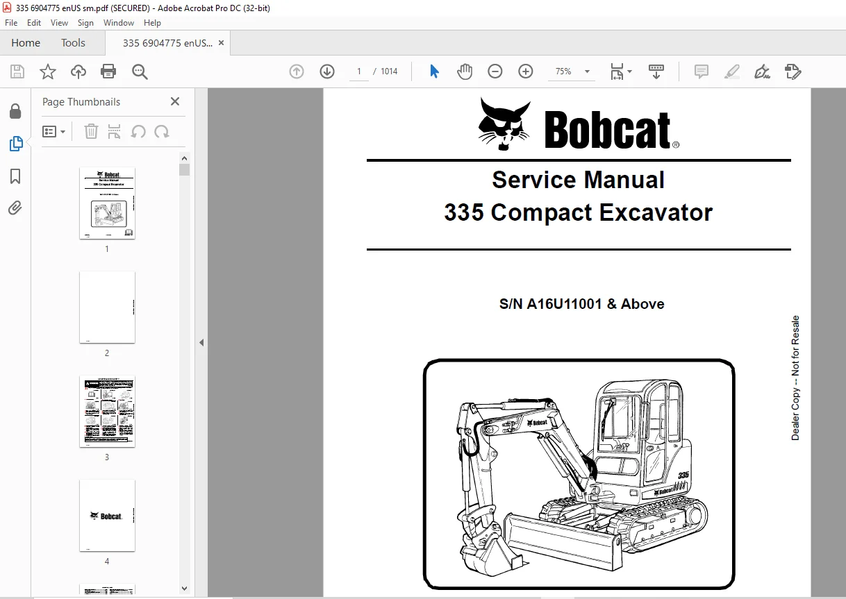
S/N A16U11001 & Above
Description
Bobcat 335 Compact Excavator Service Manual SN A16U11001 & Above – PDF DOWNLOAD
FILE DETAILS:
Bobcat 335 Compact Excavator Service Manual SN A16U11001 & Above – PDF DOWNLOAD
Language : English
Pages : 1014
Downloadable : Yes
File Type : PDF
Size:28.5 MB
DESCRIPTION:
Bobcat 335 Compact Excavator Service Manual SN A16U11001 & Above – PDF DOWNLOAD
FOREWORD
S/N A16U11001 & Above
This manual is for the Bobcat excavator mechanic. It provides necessary servicing and adjustment procedures for the Bobcat excavator and its component parts and systems. Refer to the Operation & Maintenance Manual for operating instructions, starting procedure, daily checks, etc.
SAFETY INSTRUCTIONS
Instructions are necessary before operating or servicing machine. Read and understand the Operation & Maintenance Manual, Operator’s Handbook and signs (decals) on machine. Follow warnings and instructions in the manuals when making repairs, adjustments or servicing. Check for correct function after adjustments, repairs or service. Untrained operators and failure to follow instructions can cause injury or death.
The following publications provide information on the safe use and maintenance of the Bobcat machine and attachments
TABLE OF CONTENTS:
Bobcat 335 Compact Excavator Service Manual SN A16U11001 & Above – PDF DOWNLOAD
MAINTENANCE SAFETY 3
ALPHABETICAL INDEX 5
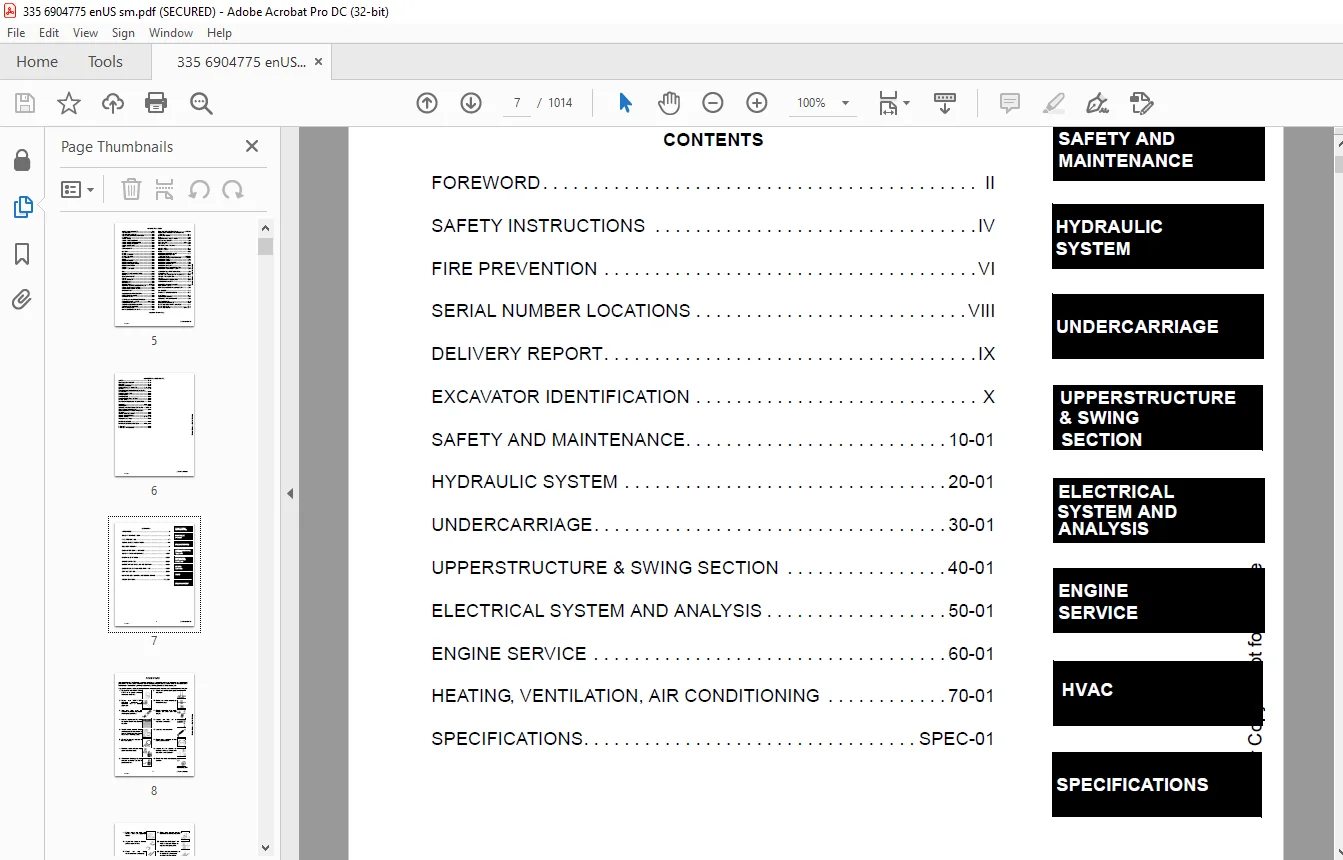
CONTENTS 7
FOREWORD 8
SAFETY INSTRUCTIONS 10
FIRE PREVENTION 12
Maintenance 12
Operation 12
Electrical 12
Hydraulic System 12
Fueling 12
Starting 12
Spark Arrestor Exhaust System 12
Welding And Grinding 13
Fire Extinguishers 13
SERIAL NUMBER LOCATIONS 14
Excavator Serial Number 14
Engine Serial Number 14
DELIVERY REPORT 15
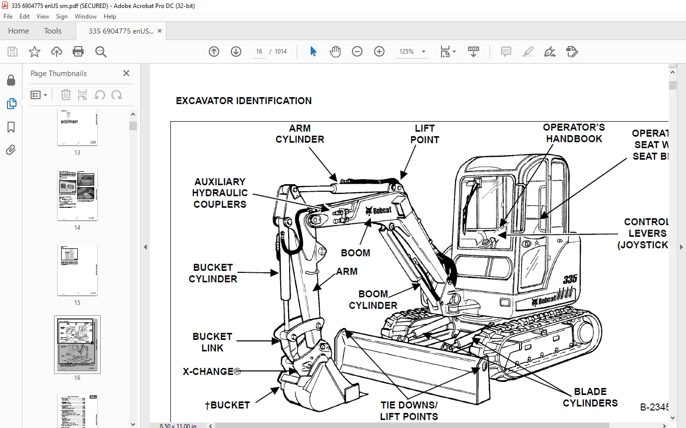
EXCAVATOR IDENTIFICATION 16
SAFETY AND MAINTENANCE 17
LIFTING AND BLOCKING THE EXCAVATOR 21
Procedure 21
UPPERSTRUCTURE SLEW LOCK 23
Operation 23
LIFTING THE EXCAVATOR 25
Procedure 25
OPERATOR CAB (ROPS / TOPS) 27
Description 27
Cab Door 27
Front Window 28
Front Wiper 30
Window Washer Reservoir 30
Right Side Window 30
Heating, Ventilation And Air Conditioning Duct 31
Heating, Ventilation And Air Conditioning Duct (Cont’d) 32
TRANSPORTING THE EXCAVATOR ON A TRAILER 33
Loading And Unloading 33
Fastening 33
TAILGATE 35
Opening And Closing 35
Adjusting The Bumper 35
Adjusting The Latch 35
RIGHT SIDE COVER 37
Opening And Closing 37
Adjusting The Bumper 37
Adjusting The Latch 37
SERVICE SCHEDULE 39
Chart 39
AIR CLEANER SERVICE 41
Daily Check 41
Replacing Filter Elements 41
HEATER AIR FILTER (WITH CAB OPTION ONLY) 43
Removal And Installation 43
ENGINE COOLING SYSTEM 45
Cleaning 45
Checking Level 45
Removing And Replacing Coolant 46
FUEL SYSTEM 47
Fuel Specifications 47
Filling The Fuel Tank 47
Fuel Filter 48
Draining The Fuel Tank 48
Removing Air From The Fuel System 49
ENGINE LUBRICATION SYSTEM 51
Checking And Adding Engine Oil 51
Engine Oil Chart 51
Removing And Replacing Oil And Filter 52
HYDRAULIC SYSTEM 53
Checking And Adding Fluid 53
Removing And Replacing Hydraulic Filter 54
Removing And Replacing Hydraulic Case Drain Filter 54
Removing And Replacing Hydraulic Fluid 55
LUBRICATING THE EXCAVATOR 57
Lubrication Locations 57
TRAVEL MOTOR 61
Checking And Adding Oil 61
Removing And Replacing Oil 61
SPARK ARRESTOR MUFFLER 63
Cleaning Procedure 63
ACCESSORY DRIVE BELT 65
Belt Adjustment 65
Belt Replacement 65
SEAT BELT 67
Inspection And Maintenance 67
PIVOT PINS 69
Inspection And Maintenance 69
EXCAVATOR STORAGE AND RETURN TO SERVICE 71
Storage 71
Return to Service 71
STOPPING THE ENGINE AND LEAVING THE EXCAVATOR 73
Procedure 73
Emergency Exits 74
HYDRAULIC SYSTEM 75
HYDRAULIC / HYDROSTATIC SCHEMATICS 81
HYDRAULIC SYSTEM INFORMATION 85
Glossary Of Hydraulic/Hydrostatic Symbols For Excavators 85
Troubleshooting The Hydraulic Circuit 89
Troubleshooting The Cylinder Circuit 90
Troubleshooting The Swing (Upperstructure Slew) Circuit 91
Troubleshooting The Travel Circuit 92
BOOM CYLINDER 93
Testing 93
Removal And Installation 95
Parts Identification 98
Disassembly 99
Assembly 101
ARM CYLINDER 105
Testing 105
Removal And Installation 107
Parts Identification 109
Disassembly 110
Assembly 112
BOOM SWING CYLINDER 115
Testing 115
Removal And Installation 117
Parts Identification 119
Disassembly 120
Assembly 122
BUCKET CYLINDER 125
Testing 125
Removal And Installation 127
Parts Identification 129
Disassembly 130
Assembly 132
BLADE CYLINDER 135
Testing 135
Removal And Installation 136
Parts Identification 137
Disassembly 138
Assembly 140
EXTENDIBLE ARM CYLINDER 143
Removal And Installation 143
Parts Identification 145
ANGLE BLADE CYLINDER 147
Testing 147
Removal And Installation 148
Parts Identification 150
Disassembly 151
Assembly 153
CLAMP CYLINDER 157
Testing 157
Removal And Installation 158
Parts Identification 159
Disassembly 160
Assembly 163
MAIN RELIEF VALVE 169
Testing And Adjusting The Main Relief Valve 169
PORT RELIEF VALVES 173
Testing And Adjusting The Port Relief Valve Pressure 173
CROSSPORT RELIEF VALVES 175
Testing And Adjusting The Crossport Relief Valve 175
PRESSURE REDUCING VALVE 179
Testing And Adjusting The Pressure Reducing Valve 179
HYDRAULIC CONTROL VALVE 181
Description 181
Removal And Installation 181
Identification Chart 184
Disassembly 185
Right Travel Valve Section Disassembly And Assembly 187
Left Travel Valve Section Disassembly And Assembly 190
Slew Valve Section Disassembly And Assembly 193
Blade Valve Section Disassembly And Assembly 199
Bucket Valve Section Disassembly And Assembly 210
Arm Valve Section Disassembly And Assembly 216
Boom Valve Section Disassembly And Assembly 222
Boom Swing Valve Section Disassembly And Assembly 228
Auxiliary Valve Section Disassembly And Assembly 234
Inlet Section Disassembly And Assembly 242
Assembly 247
HYDRAULIC PUMP 253
Piston Pump Work Sheet 253
Description 256
Testing The Piston Pump 256
Test Fitting Installation 256
Torque Limiter Adjustment 263
Testing Auxiliary Hydraulic Flow 266
Removal And Installation 268
Coupler Removal And Installation 269
Hydraulic Pump Start Up 270
Parts Identification (Torque Limiter Valve) 271
Torque Limiter Valve Removal 272
Torque Limiter Valve Disassembly 273
Torque Limiter Valve Assembly 277
Initial Torque Limiter Valve Setting 280
Torque Limiter Valve Installation 282
Parts Identification (Pump Control) 283
Pump Control Removal And Installation 284
Pump Control Disassembly And Assembly 284
Parts Identification (Piston Pump) 290
Piston Pump Disassembly 291
Piston Pump Assembly 300
MANIFOLD ASSEMBLY/ ACCUMULATOR 311
Description 311
Removal And Installation 311
Parts Identification 314
Disassembly And Assembly 315
TRAVEL MOTOR (S/N A16U11001 THROUGH A16U11490) 325
Description 325
Removal And Installation 325
Parts Identification 327
Disassembly 328
Assembly 343
TRAVEL MOTOR (S/N A16U11491 & Above) 359
Description 359
Removal And Installation 359
Parts Identification 360
Disassembly 361
Assembly 371
SWIVEL JOINT 383
Description 383
Removal And Installation 383
Parts Identification 385
Disassembly 386
Assembly 387
SWING MOTOR 391
Description 391
Removal And Installation 391
Parts Identification 393
Disassembly 394
Assembly 399
SWING MOTOR DRIVE CARRIER 405
Description 405
Removal And Installation 405
Parts Identification 406
Disassembly 407
Assembly 409
CONTROL PATTERN SELECTOR VALVE 413
Description 413
Removal And Installation 413
Parts Identification 414
Disassembly 415
Assembly 416
RIGHT CONTROL LEVER (JOYSTICK) 417
Description 417
Testing 417
Handle Removal And Installation 418
Removal And Installation 422
Parts Identification 425
Disassembly 426
Assembly 431
LEFT CONTROL LEVER (JOYSTICK) 437
Description 437
Testing 437
Handle Removal And Installation 438
Removal And Installation 441
Parts Identification 444
Disassembly 445
Assembly 450
HYDRAULIC FILTER 455
Description 455
Housing Removal And Installation 455
CASE DRAIN FILTER 457
Description 457
Housing Removal And Installation 457
HYDRAULIC RESERVOIR 459
Description 459
Removal And Installation 459
OIL COOLER 461
Description 461
Removal And Installation 461
DIRECT TO TANK VALVE 463
Description 463
Removal And Installation 463
Parts Identification 464
Disassembly And Assembly 465
HYDRAULIC X-CHANGE VALVE 467
Removal And Installation 467
Parts Identification 471
Disassembly 472
Assembly 480
BOOM SWING LOCK VALVE 489
Removal And Installation 489
Parts Identification 490
Disassembly 491
Assembly 494
TRAVEL CONTROL VALVE 499
Removal and Installation 499
Parts Identification 500
Disassembly And Assembly 501
ANGLE BLADE VALVE 505
Description 505
Testing And Adjusting Port Relief Valves 505
Testing And Adjusting Sequence Valve 507
Removal And Installation 509
Parts Identification 512
Disassembly 513
Assembly 526
UNDERCARRIAGE 539
BLADE 541
Description 541
Blade Removal And Installation 541
ANGLE BLADE ASSEMBLY 543
Removal And Installation 543
ANGLE BLADE 545
Removal And Installation 545
ANGLE BLADE CUTTING EDGE 547
Removal And Installation 547
TRACK FRAME COMPONENTS 549
Description 549
Track Lug Height 549
Checking Tension 550
Adjusting Tension 552
Rubber Track Removal And Installation 553
Steel Track Removal And Installation 556
Idler (Front) Removal And Installation 561
Idler (Front) Parts Identification 562
Idler (Front) Disassembly 563
Idler (Front) Assembly 565
Recoil Spring Assembly And Cylinder Removal And Installation 568
Recoil Spring Assembly And Cylinder Disassembly And Assembly (Without Replaceable Shaft) 569
Recoil Spring Cylinder Parts Identification (With Replaceable Shaft) 570
Recoil Spring Assembly And Cylinder Disassembly And Assembly (With Replaceable Shaft) 571
Roller Removal And Installation 573
Upper Roller Parts Identification 574
Upper Roller Disassembly 575
Upper Roller Assembly 576
Lower Roller Parts Identification 579
Lower Roller Disassembly 580
Lower Roller Assembly 581
Track Guide Removal And Installation 584
Sprocket Removal And Installation 584
Track Damage Identification 585
SWING CIRCLE GEAR 595
Removal 595
Installation 596
UPPERSTRUCTURE & SWING SECTION 597
UPPERSTRUCTURE 601
Description 601
Removal 601
Installation 604
CANOPY 607
Removal And Installation 607
CAB 611
Removal And Installation 611
Door Removal And Installation 616
Front Window Removal And Installation 617
Right Side Rear Sliding Window Removal And Installation 620
Right Side Front Sliding Window Removal And Installation 620
Glass Removal 621
Right Side Front And Rear Sliding Window Weather Strip Removal And Installation 622
Right Side Front And Rear Sliding Window Wiper Strip Removal And Installation 622
Glass Installation 623
SEAT AND SEAT MOUNT 629
Seat Mount Removal And Installation 629
Seat Removal And Installation 629
RIGHT CONSOLE 631
Description 631
Console Cover Removal And Installation 631
Console Frame Removal And Installation 632
Console Frame Disassembly And Assembly 634
LEFT CONSOLE 635
Description 635
Joystick Console Cover (Bottom) Removal And Installation 635
Joystick Console Cover (Top) Removal And Installation 635
Left Rear Console Cover Removal And Installation 637
Compression Spring Removal And Installation 638
Compression Spring Disassembly And Assembly 639
Lever Removal And Installation 641
Joystick Console Frame Removal And Installation 643
Joystick Console Frame Disassembly And Assembly 647
Left Console Frame Removal And Installation 650
BLADE CONTROL 651
Removal And Installation 651
Linkage Removal And Installation 652
Linkage Disassembly And Assembly 653
UPPERSTRUCTURE SLEW LOCK 655
Removal And Installation 655
Disassembly And Assembly 655
Disassembly And Assembly (Cont’d) 656
FLOOR MAT & FLOOR PANEL 657
Description 657
Removal And Installation (Canopy Equipped) 657
Removal And Installation (Cab Equipped) 659
BOOM SWING PEDAL 663
Description 663
Removal And Installation 663
Disassembly And Assembly 664
Linkage Removal And Installation 666
TRAVEL LEVER/PEDALS 667
Description 667
Removal And Installation 667
Disassembly And Assembly 668
Adjustment 670
Linkage Removal And Installation 672
FUEL TANK 673
Removal And Installation 673
HORN 677
Removal And Installation (Early Models) 677
Removal And Installation (Later Models) 678
SWING FRAME 679
Description 679
Removal And Installation 679
Hose Routing 683
Bushing Removal And Installation 684
Swing Frame Bushing Removal And Installation 684
BOOM 687
Description 687
Removal And Installation 687
Boom Bushing Removal And Installation 688
ARM 689
Description 689
Removal And Installation 689
Arm To Boom Bushing Removal And Installation 690
Arm To Bucket & Bucket Link Bushing Removal And Installation 691
BUCKET 693
Removal And Installation (Pin-On X-Change) 693
Removal And Installation (Bolt-On X-Change) 699
Removal And Installation (Hydraulic X-Change) 705
Bucket Teeth Removal And Installation 711
Bucket Side Cutting Edge Removal And Installation 712
CLAMP 715
Removal And Installation 715
TAILGATE 717
Removal And Installation 717
Latch Removal And Installation 718
X-CHANGE 719
Pin-On Removal And Installation 719
Pin-On Disassembly and Assembly 720
X-CHANGE (HYDRAULIC) 721
Removal And Installation 721
Parts Identification 724
Disassembly 725
Assembly 730
RIGHT SIDE COVER 739
Removal And Installation 739
Latch Removal And Installation 740
ELECTRICAL SYSTEM AND ANALYSIS 741
ELECTRICAL SCHEMATICS 743
ELECTRICAL SYSTEM INFORMATION 745
Glossary Of Electrical Symbols 745
Harness Connectors 748
Troubleshooting 750
Description 751
Fuse And Relay Locations/Identification 751
BATTERY 753
Removal And Installation 753
Servicing 754
Using A Booster Battery (Jump Starting) 755
ALTERNATOR 757
Belt Adjustment 757
Charging System Inspection 758
Alternator Voltage Testing 759
Low Voltage Testing 759
High Voltage Testing 760
Removal And Installation 761
Parts Identification 763
STARTER 765
Testing 765
Removal And Installation 766
Part Identification 767
LIGHTS 769
Upperstructure Light Removal And Installation 769
Upperstructure Light Disassembly And Assembly 769
Boom Light Removal And Installation (Early Models) 770
Boom Light Disassembly And Assembly (Early Models) 770
Boom Light Removal And Installation (Later Models) 771
Boom Light Bulb Replacement (Later Models) 771
MAGNETIC LOCKOUT SENSOR 773
Testing Left Console Magnetic Lockout Sensor 773
Left Console Magnetic Lockout Sensor Removal And Installation 774
FUEL LEVEL SENDER 777
Removal And Installation 777
Testing 778
DIAGNOSTIC SERVICE CODES 779
Description 779
Service Codes List 780
DELUXE INSTRUMENT PANEL SETUP 781
Passwords 781
Password Entry (For Starting and Operating the Machine) 781
Changing The Owner Or Operator Password 781
Password Lockout Feature 782
Job Clock 782
RPM 782
ENGINE SERVICE 783
ENGINE INFORMATION 785
Description 785
Specifications 786
Fuel Injection Nozzles 786
Fuel Injection Pump 786
Cylinder Head 786
Valves 786
Valve Springs 787
Valve Timing 787
Rocker Arms 787
Camshaft 787
Tappet 787
Cylinders 788
Piston Rings 788
Pistons 788
Connecting Rods 788
Oil Pump 788
Crankshaft 789
Timing Gear 789
Thermostat 789
Engine Bolt Torque 790
Crankshaft Re-Grind Data 791
Torque Values 792
Troubleshooting 792
Engine Removal And Installation 794
Engine Mount Replacement 800
Compression – Checking 803
ENGINE SPEED CONTROL 805
Removal And Installation 805
Adjustment (Later Models) 806
SPARK ARRESTOR MUFFLER 807
Removal And Installation 807
AIR CLEANER 809
Removal And Installation 809
ENGINE COOLING SYSTEM 811
Radiator Removal And Installation 811
Water Pump Removal And Installation 813
Water Pump Disassembly And Assembly 813
Thermostat Housing Removal And Installation 814
Testing The Thermostat 815
LUBRICATION SYSTEM 817
Oil Pan Removal And Installation 817
Oil Pump Removal And Installation 817
Oil Pump Inspection 818
Engine Oil Pressure – Testing 819
FUEL SYSTEM 821
Fuel Camshaft Removal And Installation 821
Fuel Camshaft Governor Disassembly And Assembly 822
Fuel ShutOff Solenoid – Checking 823
Fuel Shutoff Solenoid Removal And Installation 824
Fuel Injection Pump Removal And Installation 825
Injection Pump – Timing 828
Fuel Injector Removal And Installation 830
Fuel Injector Nozzle Pressure – Checking 832
Nozzle Spray Condition 832
Valve Seat Tightness 833
ENGINE FLYWHEEL (LATER MODELS) 835
Flywheel Removal And Installation 835
Hydraulic Pump Coupler 837
Flywheel Ring Gear 837
CYLINDER HEAD 839
Glow Plug – Testing 839
Glow Plug Removal And Installation 840
Valve Clearance Adjustment 841
Valve Timing – Checking 842
Cylinder Head Removal And Installation 843
Cylinder Head Disassembly And Assembly 846
Cylinder Head Servicing 846
Cylinder Head Top Clearance 847
Valve Guide – Checking 847
Reconditioning The Valve And Valve Seat 849
Valve Spring 850
Valve Tappets 851
Rocker Arm And Shaft – Checking 851
CRANKSHAFT AND PISTONS 853
Piston And Connecting Rod Removal And Installation 853
Piston And Connecting Rod – Servicing 855
Cylinder Bore – Checking 857
Connecting Rod – Alignment 857
Crankshaft And Bearings Removal And Installation 858
Crankshaft And Bearings – Servicing 860
CAMSHAFT AND TIMING GEARS 865
Timing Gearcase Cover Removal And Installation 865
Timing Gears Backlash – Checking 867
Idler Gear And Shaft Removal And Installation 868
Camshaft – Servicing 869
Idler Gear And Shaft – Servicing 870
FLYWHEEL AND HOUSING 871
Flywheel Housing Removal And Installation 871
Hydraulic Pump Coupler Removal And Installation 872
Flywheel Removal And Installation 872
FAN 873
Removal And Installation 873
HEATING, VENTILATION, AIR CONDITIONING 875
HEATER COIL (EARLY MODELS) 879
Removal And Installation With A/C 879
Removal And Installation Without A/C 879
HEATER COIL (LATER MODELS) 881
Removal And Installation With A/C 881
Removal And Installation Without A/C 881
BLOWER FAN (EARLY MODELS) 883
Removal And Installation 883
Connector Identification 883
Disassembly And Assembly 884
BLOWER FAN (LATER MODELS) 887
Removal And Installation 887
Disassembly And Assembly 888
Resistor Removal And Installation 889
HEATER VALVE 891
Removal And Installation 891
AIR CONDITIONING SYSTEM FLOW 894
Principals 894
Chart 895
COMPONENTS 897
Identification 897
SAFETY 901
Safety Equipment 901
REGULAR MAINTENANCE 903
Heater Air Filter 903
Engine Accessory Drive Belt 903
Cleaning The Condenser 903
BASIC TROUBLESHOOTING (EARLY MODELS) 905
Poor A/C Performance 905
Cleaning The A/C Evaporator Coil & Heater Coil 906
Engine Accessory Drive Belt Inspection 907
Checking The Electrical System 908
Engine Coolant By-Passing The Heater Valve 917
Heater Valve Not Opening Or Closing 918
BASIC TROUBLESHOOTING (LATER MODELS) 921
Poor A/C Performance 921
Cleaning The A/C Evaporator Coil & Heater Coil 922
Engine Accessory Drive Belt 923
Electrical System 924
Engine Coolant By-Passing The Heater Valve 933
Heater Valve Not Opening Or Closing 934
GENERAL AIR CONDITIONING SERVICE GUIDELINES 937
Compressor Oil 937
Compressor Oil Check 938
Component Replacement And Refrigeration Leaks 939
SYSTEM TROUBLESHOOTING CHART 941
Blower Motor Does Not Operate 941
Gauge Pressure Related Troubleshooting 942
TEMPERATURE/PRESSURE 945
Chart 945
AIR CONDITIONING SERVICE 947
Chart 947
SYSTEM CHARGING AND RECLAMATION 949
Reclamation Procedure 949
Charging With A Manifold Gauge Set 952
COMPRESSOR 955
Removal And Installation 955
Clutch Disassembly And Assembly 957
CONDENSER 961
Removal And Installation 961
RECEIVER/DRIER 963
Receiver/Drier Removal And Installation 963
PRESSURE RELIEF VALVE 965
Removal And Installation 965
PRESSURE SWITCH 967
Removal And Installation 967
EVAPORATOR/HEATER UNIT (EARLY MODELS) 969
Removal And Installation 969
Disassembly And Assembly 970
EVAPORATOR/HEATER UNIT (LATER MODELS) 971
Removal And Installation 971
Disassembly And Assembly 972
THERMOSTAT (EARLY MODELS) 973
Removal And Installation 973
THERMOSTAT (LATER MODELS) 975
Removal And Installation 975
EXPANSION VALVE (EARLY MODELS) 977
Removal And Installation 977
EXPANSION VALVE (LATER MODELS) 979
Removal And Installation 979
EVAPORATOR COIL (EARLY MODELS) 981
Removal And Installation 981
EVAPORATOR (LATER MODELS) 983
Removal And Installation 983
SPECIFICATIONS 985
EXCAVATOR SPECIFICATIONS 987
Dimensions 987
Performance 989
Controls 989
Engine 989
Hydraulic System 990
Hydraulic Cylinders 990
Hydraulic Cycle Times 990
Electrical 991
Drive System 991
Slew System 991
Undercarriage 991
Capacities 991
Tracks 991
Ground Pressure 991
TORQUE SPECIFICATIONS FOR BOLTS 993
Torque For General SAE Bolts 993
Torque For General Metric Bolts 994
HYDRAULIC CONNECTION SPECIFICATIONS 995
O-ring Face Seal Connection 995
Straight Thread O-ring Fitting 996
Tubelines And Hoses 996
Flare Fitting 996
Port Seal Fitting 997
HYDRAULIC FLUID SPECIFICATIONS 999
Specifications 999
CONVERSIONS 1001
Decimal And Millimeter Equivalents 1001
U S To Metric Conversion Chart 1001
SERVICE MANUAL REVISION 1003
Revision No: 335 – 1 1003
Revision No: 335 – 2 1005
Revision No: 335 – 3 1007
Revision No: 335 – 4 1009
Revision No: 335 – 5 1011
Revision No: 335 – 6 1013
IMAGES PREVIEW OF THE MANUAL:
Contact us: [email protected]
https://vimeo.com/841235096?share=copy
PLEASE NOTE:
- This is the same manual used by the DEALERSHIPS to SERVICE your vehicle.
- The manual can be all yours – Once payment is complete, you will be taken to the download page from where you can download the manual. All in 2-5 minutes time!!
- Need any other service / repair / parts manual, please feel free to contact us at heydownloadss @gmail.com . We may surprise you with a nice offer
S.M