Bobcat 337, 341 Compact Excavator Service Manual 6902741 (10-11) – PDF DOWNLOAD
$35.95
Bobcat 337, 341 Compact Excavator Service Manual 6902741 (10-11) – PDF DOWNLOAD
337 – S/N 234611001 & Above
341 – S/N 234711001 & Above
(G Series)
Description
Bobcat 337, 341 Compact Excavator Service Manual 6902741 (10-11) – PDF DOWNLOAD
FILE DETAILS:
Bobcat 337, 341 Compact Excavator Service Manual 6902741 (10-11) – PDF DOWNLOAD
Language : English
Pages :1087
Downloadable : Yes
File Type : PDF
Size:44.2 MB
DESCRIPTION:
Bobcat 337, 341 Compact Excavator Service Manual 6902741 (10-11) – PDF DOWNLOAD
FOREWORD
This manual is for the Bobcat excavator mechanic. It provides necessary servicing and adjustment procedures for the Bobcat excavator and its component parts and systems. Refer to the Operation & Maintenance Manual for operating instructions, starting procedure, daily checks, etc
A general inspection of the following items must be made after the excavator has had service or repair:
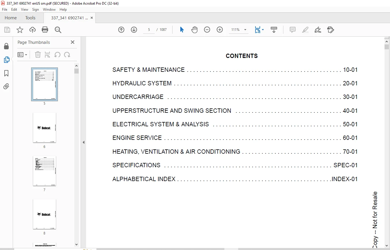
TABLE OF CONTENTS:
Bobcat 337, 341 Compact Excavator Service Manual 6902741 (10-11) – PDF DOWNLOAD
MAINTENANCE SAFETY 3
CONTENTS 5
FOREWORD 7
FOREWORD 9
SAFETY INSTRUCTIONS 11
FIRE PREVENTION 13
Maintenance 13
Operation 13
Electrical 13
Hydraulic System 13
Fueling 13
Starting 13
Spark Arrester Exhaust System 13
Welding And Grinding 14
Fire Extinguishers 14
SERIAL NUMBER LOCATIONS 15
Excavator Serial Number 15
Engine Serial Number 15
DELIVERY REPORT 16
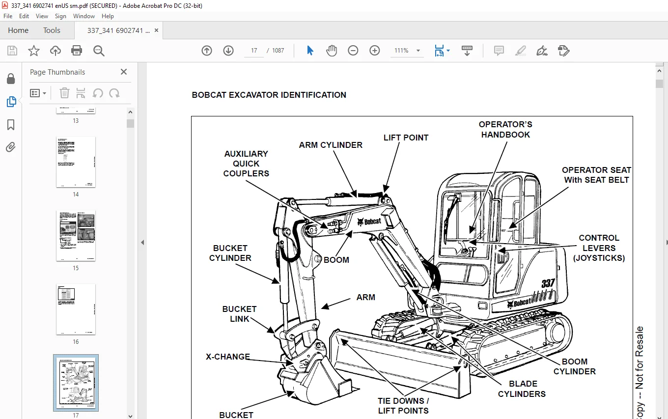
BOBCAT EXCAVATOR IDENTIFICATION 17
SAFETY & MAINTENANCE 19
LIFTING AND BLOCKING THE EXCAVATOR 21
Procedure 21
LIFTING THE EXCAVATOR 23
Procedure 23
OPERATOR CAB (ROPS / TOPS) 25
Emergency Exit 25
Cab Door 26
TRANSPORTING THE EXCAVATOR 27
Loading And Unloading 27
Fastening 27
TAILGATE 29
Opening And Closing The Tailgate 29
Adjusting The Bumper 29
Adjusting The Latch 29
RIGHT SIDE COVER 31
Opening And Closing The Right Side Cover 31
SERVICE SCHEDULE 33
Chart 33
AIR CLEANER 35
Checking 35
Replacing The Filters 35
HEATER AIR FILTER 37
Fresh Air Filter 37
COOLING SYSTEM 39
Cleaning The Cooling System 39
Checking Coolant Level 39
Replacing The Coolant 40
FUEL SYSTEM 41
Fuel Specifications 41
Filling The Fuel Tank 41
Removing Water From The Fuel Filter 41
Draining The Fuel Tank 42
Fuel Filter 42
Removing Air From The Fuel System 43
ENGINE LUBRICATION SYSTEM 45
Checking Engine Oil 45
Oil Chart 45
Replacing Oil And Filter 46
HYDRAULIC SYSTEM 47
Checking And Adding Hydraulic Oil 47
Replacing The Hydraulic Oil 48
Replacing The Hydraulic Filter 49
Replacing The Case Drain Filter 49
Diagnostic Couplers 50
LUBRICATION OF THE EXCAVATOR 51
Procedure 51
TRAVEL MOTOR 55
Checking Oil Level 55
Draining The Travel Motor 55
SPARK ARRESTER MUFFLER 57
Cleaning procedure 57
ENGINE ACCESSORY DRIVE BELT 59
Belt Tension 59
Belt Adjustment 59
SEAT BELT 61
Inspection And Maintenance 61
REMOTE START TOOL KIT – MEL1563 63
Remote Start Tool – MEL1563 63
Service Tool Harness Communicator – MEL1566 65
REMOTE START TOOL (SERVICE TOOL) KIT – 7003031 67
Description 67
Remote Start Tool (Service Tool) – 7003030 68
Excavator Service Tool Harness – 6689747 69
Computer Service Tool Harness – 6689746 70
HYDRAULIC SYSTEM 71
HYDRAULIC / HYDROSTATIC SCHEMATICS 77
HYDRAULIC SYSTEM INFORMATION 83
Glossary Of Hydraulic / Hydrostatic Symbols For Excavators 83
Troubleshooting The Hydraulic Circuit 86
Troubleshooting The Cylinder Circuit 87
Troubleshooting The Upperstructure Slew Circuit 88
Troubleshooting The Travel Circuit 89
Description 90
BOOM CYLINDER 93
Testing 93
Removal And Installation 95
Parts Identification 97
Disassembly 98
Assembly 102
ARM CYLINDER 107
Testing 107
Removal and Installation 109
Parts Identification 111
Disassembly 112
Assembly 115
BOOM SWING CYLINDER 119
Testing 119
Removal And Installation 120
Parts Identification 122
Disassembly 123
Assembly 126
BUCKET CYLINDER 131
Testing 131
Removal And Installation 133
Parts Identification 134
Disassembly 135
Assembly 137
BLADE CYLINDER 141
Testing 141
Removal And Installation 142
Parts Identification 143
Disassembly 144
Assembly 146
CLAMP CYLINDER 149
Testing 149
Removal And Installation 150
Parts Identification 151
Disassembly 152
Assembly 155
MAIN RELIEF VALVE 161
PORT RELIEF VALVES 163
Port Relief Valve Pressure Setting 163
Parts Identification 163
Adjustment Procedure 164
CROSSPORT RELIEF VALVE 165
Testing And Adjusting The Crossport Relief Valve 165
Removal And Installation 168
Parts Identification 169
Disassembly And Assembly 170
PRESSURE REDUCING VALVE 175
Description 175
HYDRAULIC CONTROL VALVE 177
Removal And Installation 177
Parts Identification 181
Disassembly And Assembly 182
Slew Valve Section 183
Boom Swing Valve Section 192
Blade Valve Section (S/N 234611001-234611163 And S/N 234711001-234711197) 199
Blade Valve Section (S/N 234611164 & Above And 234711198 & Above) 207
Bucket Valve Section 218
Arm Valve Section 224
Boom Valve Section 230
Auxiliary Valve Section 236
Right Travel Valve Section 244
Left Travel Valve Section 248
Inlet Section 252
HYDRAULIC PUMP (S/N 234611001 – 234613190, 234613193 – 234613247, 234711001 – 234713440) 257
Hydraulic Pump Work Sheet 257
Pump Testing 260
Removal And Installation 273
Coupler Removal And Installation 274
Hydraulic Pump Start Up 275
Torque Limiter Valve Parts Identification 276
Torque Limiter Valve Removal 277
Torque Limiter Valve Disassembly 277
Torque Limiter Valve Assembly 282
Initial Torque Limiter Valve Setting 285
Torque Limiter Valve Installation 287
Pump Control Parts Identification 288
Pump Control Removal And Installation 289
Pump Control Disassembly And Assembly 289
Parts Identification 295
Disassembly 296
Assembly 305
HYDRAULIC PUMP (S/N 234613191, 234613192, 234613248 & ABOVE, 2347133441 & ABOVE) 315
Hydraulic Pump Work Sheet 315
Pump Testing 318
Removal And Installation 330
Coupler Removal And Installation 331
Hydraulic Pump Start Up 332
Torque Limiter Assembly Parts Identification 333
Torque Limiter Valve Assembly Removal And Installation 334
Torque Limiter Valve Assembly Disassembly And Assembly 334
Pump Control Parts Identification 335
Pump Control Removal And Installation 336
Pump Control Disassembly And Assembly 336
Parts Identification 342
Disassembly And Assembly 343
MANIFOLD ASSEMBLY / ACCUMULATOR 351
Description 351
Testing Pilot Pressure 351
Adjusting The Pilot Pressure 353
Removal And Installation 354
Manifold Assembly / Accumulator Parts Identification 357
Disassembly And Assembly 358
TRAVEL MOTOR 369
Removal And Installation 369
Parts Identification 370
Disassembly 371
Assembly 381
SWIVEL JOINT 393
Removal And Installation 393
Parts Identification 394
Disassembly 395
Assembly 396
SWING MOTOR 401
Removal And Installation 401
Parts Identification 405
Disassembly 406
Inspection 410
Assembly 411
SWING MOTOR DRIVE CARRIER 417
Removal And Installation 417
Parts Identification 419
Checking The Drive Carrier Shaft End Play 420
Disassembly 421
Inspection 423
Assembly 424
CONTROL PATTERN SELECTOR VALVE 429
Removal And Installation 429
Parts Identification 430
Disassembly 431
Assembly 432
RIGHT CONTROL LEVER (JOYSTICK) 433
Testing 433
Handle Removal And Installation 435
Joystick Assembly Removal And Installation 439
Parts Identification 442
Disassembly 443
Assembly 448
LEFT CONTROL LEVER (JOYSTICK) 453
Testing 453
Handle Removal And Installation 455
Joystick Assembly Removal And Installation 458
Parts Identification 460
Disassembly 461
Assembly 466
TRAVEL CONTROL VALVE 471
Removal and Installation 471
Parts Identification 473
Disassembly And Assembly 474
HYDRAULIC FILTER MOUNT 477
Removal And Installation 477
HYDRAULIC RESERVOIR 479
Removal And Installation 479
OIL COOLER 483
Removal And Installation 483
DUAL SEQUENCE VALVE 485
Removal And Installation 485
Parts Identification 487
Disassembly And Assembly 488
DIRECT TO TANK VALVE 491
Removal And Installation 491
Parts Identification 492
Disassembly And Assembly 493
BUILD UP VALVE 495
Removal And Installation 495
Parts Identification 496
Disassembly And Assembly 497
CASE DRAIN FILTER MOUNT 501
Removal And Installation 501
REMOVING AIR FROM HYDRAULIC SYSTEM 503
Procedure 503
BOOM SWING LOCK VALVE 505
Description 505
Removal And Installation 505
Parts Identification 507
Disassembly 508
Assembly 511
HYDRAULIC X-CHANGE VALVE 515
Removal And Installation 515
Parts Identification 519
Disassembly 520
Assembly 528
UNDERCARRIAGE 535
BLADE 537
Removal And Installation 537
TRACKS 539
Track Lug Height 539
Rubber Track Clearance 540
Rubber Track Adjustment 541
Steel Track Clearance 542
Steel Track Adjustment 543
Rubber Track Removal And Installation 544
Steel Track Removal 547
Steel Track Installation 549
Track Shoe Removal And Installation 551
TRACK FRAME (S/N 234611163 & BELOW AND 234711197 & BELOW) 553
Disassembly And Assembly 553
Recoil Spring Cylinder Disassembly And Assembly (W/O Replaceable Shaft) 556
Recoil Spring Cylinder Parts Identification (With Replaceable Shaft) 557
Recoil Spring Cylinder Disassembly And Assembly (With Replaceable Shaft) 558
TRACK FRAME (S/N 234611164 & ABOVE AND 234711198 & ABOVE) 561
Disassembly And Assembly 561
Recoil Spring Cylinder Disassembly And Assembly (W/O Replaceable Shaft) 564
Recoil Spring Cylinder Parts Identification (With Replaceable Shaft) 565
Recoil Spring Cylinder Disassembly And Assembly (With Replaceable Shaft) 566
TRACK DAMAGE IDENTIFICATION 569
Cutting Of Steel Cords 569
Abrasion Of Embedded Metals 570
Separation Of Embedded Metals 571
Separation Of Embedded Metals Due To Corrosion 572
Cuts On The Lug Side Rubber 573
Cracks On The Lug Side Rubber Due To Fatigue 574
Lug Abrasion 575
Cracks And Cuts On The Lug Side Rubber 576
Abrasion Of The Track Roller Side 577
Cuts On The Edges Of Track Roller Side 578
TRACK IDLER (S/N 234611163 & BELOW AND 234711197 & BELOW) 581
Parts Identification 581
Disassembly 582
Assembly 584
TRACK IDLER (S/N 234611164 & ABOVE AND 234711198 & ABOVE) 587
Parts Identification 587
Disassembly 588
Assembly 590
TRACK ROLLER (S/N 234611163 & BELOW AND 234711197 & BELOW) 593
Parts Identification 593
Disassembly 594
Assembly 596
TRACK ROLLER (S/N 234611164 & ABOVE AND 234711198 & ABOVE) 599
Parts Identification (Upper Roller) 599
Disassembly (Upper Roller) 600
Assembly (Upper Roller) 602
Parts Identification (Lower Roller) 604
Disassembly (Lower Roller) 605
Assembly (Lower Roller) 607
SWING CIRCLE GEAR (S/N 234611163 & BELOW AND 234711197 & BELOW) 609
Swing Bearing Removal 609
Swing Bearing Installation 610
SWING CIRCLE GEAR (S/N 234611164 & ABOVE AND 234711198 & ABOVE) 611
Swing Bearing Removal 611
Swing Bearing Installation 612
UPPERSTRUCTURE AND SWING SECTION 613
UPPERSTRUCTURE 617
Removal 617
Installation 620
ROPS CANOPY 623
Removal And Installation 623
CAB 627
Removal And Installation 627
Door Removal And Installation 632
Front Window Removal And Installation 633
Right Side Rear Sliding Window Removal And Installation 636
Right Side Front Sliding Window Removal And Installation 637
Right Side Front And Rear Sliding Window Weather Strip Removal And Installation 638
Right Side Front And Rear Sliding Window Wiper Strip Removal And Installation 638
Glass Removal 639
Glass Installation 640
SEAT AND SEAT MOUNT 643
Removal And Installation 643
RIGHT CONSOLE 645
Console Cover Removal And Installation 645
Console Base Removal And Installation 646
LEFT CONSOLE 649
Lower Console Cover Removal And Installation 649
Upper Console Cover Removal And Installation 651
Compression Spring Removal And Installation 652
Compression Spring Disassembly And Assembly 653
Lock Lever Removal And Installation 655
Console Removal And Installation 656
Disassembly And Assembly 662
Console Switch Removal And Installation 665
Console Base Removal And Installation 666
ENGINE SPEED CONTROL 667
Removal And Installation 667
Adjustment (Later Models) 668
BLADE CONTROL 669
Lever Removal And Installation 669
Linkage Removal And Installation 670
Linkage Disassembly And Assembly 671
Linkage Bar Removal And Installation 673
Lower Linkage Removal And Installation 674
Lower Linkage Disassembly And Assembly 676
RIGHT PEDAL AND LINKAGE 679
Pedal Removal And Installation 679
Pedal Disassembly And Assembly 680
Lower Linkage Removal And Installation 682
Lower Linkage Disassembly And Assembly 684
Bellcrank Removal And Installation 685
TRAVEL CONTROLS 687
Removal And Installation 687
Disassembly And Assembly 688
Adjustment 690
CONTROL LINKAGE ASSEMBLY 693
Removal And Installation 693
FLOOR MAT AND FLOOR PLATE 695
Removal And Installation 695
FUEL TANK 697
Removal And Installation 697
HORN 699
Removal And Installation 699
SWING FRAME 701
Boom Swing Bracket Removal And Installation 701
Boom Swing Bracket Hose Installation 705
Swing Bracket Bushing Removal 706
Swing Bracket Bushing Installation 707
Boom Pivot Pin Bushing Removal 708
Boom Pivot Pin Bushing Installation 709
BOOM 711
Removal And Installation 711
Boom Pivot Pin Bushing Removal And Installation 712
ARM 713
Removal And Installation 713
BUCKET 715
Bucket Teeth Removal And Installation 715
CLAMP 717
Removal And Installation 717
TAILGATE 719
Removal And Installation 719
Latch Removal And Installation 720
Striker Removal And Installation 721
X-CHANGE 723
Removal And Installation 723
Parts Identification 725
Disassembly 726
Assembly 731
Check Proper Latch Engagement 737
X-CHANGE (PIN ON) 741
Removal And Installation 741
Parts Identification 743
Disassembly And Assembly 744
X-CHANGE (HYDRAULIC) 745
Removal And Installation 745
Parts Identification 748
Disassembly 749
Assembly 754
QUICK COUPLER (KLAC™ SYSTEM) 763
Troubleshooting 763
Daily Inspection 763
Removal And Installation 764
Parts Identification 766
Disassembly 767
Assembly 768
QUICK COUPLER (LEHNHOFF® SYSTEM) 771
Troubleshooting 771
Daily Inspection 771
Removal (MS03 And MS08) 772
Installation (MS03 And MS08) 773
Parts Identification (MS03) 774
Disassembly And Assembly (MS03) 775
Parts Identification (MS08) 776
Disassembly (MS08) 777
Assembly (MS08) 780
ELECTRICAL SYSTEM & ANALYSIS 785
ELECTRICAL SCHEMATICS 787
ELECTRICAL SYSTEM INFORMATION 790
Troubleshooting Chart 790
Description 791
Fuse And Relay Location 791
BATTERY 792
Servicing 792
Removing And Installing The Battery 793
Using A Booster Battery (Jump Starting) 794
ALTERNATOR 796
Engine Accessory Drive Belt 796
Removal And Installation 797
Alternator Identification 799
Charging System Check 800
Alternator Voltage Test 801
Low Voltage Test 802
High Voltage Test 803
Rectifier Continuity (Diode) Test 804
Alternator Regulator Test 805
Parts Identification 806
Disassembly 807
Stator Continuity Test 808
Stator Ground Test 808
Rotor Continuity Test 808
Rotor Ground Test 808
Assembly 809
STARTER 810
Removal And Installation 810
Parts Identification 811
Disassembly 812
Inspection And Repair 817
Assembly 820
LIGHTS 826
Removal And Installation 826
Disassembly And Assembly 828
TWO-SPEED SWITCH 830
Removal And Installation 830
FUEL LEVEL SENDER 832
Removal And Installation 832
Testing And Inspection 833
DIAGNOSTICS SERVICE CODE 834
Number Codes List 834
DELUXE INSTRUMENT PANEL SETUP 836
Passwords 836
Password Entry (For Starting And Operating The Machine) 836
Changing The Owner or Operator Password 836
Password Lockout Feature 837
Job Clock 837
RPM 837
ENGINE SERVICE 838
TROUBLESHOOTING 840
Chart 840
MUFFLER 842
Removal And Installation 842
AIR CLEANER 844
Removal And Installation 844
RADIATOR 846
Removal And Installation 846
ENGINE COMPONENTS AND TESTING 848
Engine Compression Checking 848
Glow Plugs Removal And Installation 849
Checking The Glow Plug 850
Fuel Shut-off Solenoid Removal And Installation 851
Fuel Injection Pump Check 852
Fuel Injection Pump Removal And Installation 852
Fuel Injection Pump Timing 856
Fuel Injector Nozzles Removal And Installation 858
Fuel Injector Nozzle Check 861
Valve Clearance Adjustment 862
ENGINE 864
Removal And Installation 864
ENGINE FLYWHEEL (EARLY MODELS) 870
Flywheel Removal And Installation 870
Hydraulic Pump Coupler 872
Flywheel Ring Gear 872
ENGINE FLYWHEEL (LATER MODELS) 874
Flywheel Removal And Installation 874
Hydraulic Pump Coupler 877
Flywheel Ring Gear 877
RECONDITIONING THE ENGINE 878
Cylinder Head Removal And Installation 878
Cylinder Head Disassembly And Assembly 881
Cylinder Head Servicing 882
Cylinder Head Top Clearance 882
Valve Guide Checking 883
Reconditioning The Valve And Valve Seat 885
Valve Spring 886
Rocker Arm And Shaft Checking 887
Timing Gearcase Cover Removal And Installation 888
Idler Gear And Camshaft Removal And Installation 891
Camshaft Servicing 892
Idler Gear And Shaft Servicing 893
Timing Gears Checking Backlash 894
Fuel Camshaft Removal And Installation 894
Fuel Camshaft Governor 895
Crankshaft Gear Removal And Installation 895
Oil Pump Removal And Installation 896
Oil Pump Service 896
Checking Engine Oil Pressure 897
Valve Tappets 898
Piston And Connecting Rod Removal And Installation 898
Piston And Connecting Rod Servicing 900
Connecting Rod Alignment 902
Crankshaft And Bearings Removal And Installation 903
Crankshaft And Bearings, Servicing 905
Cylinder Bore, Checking 909
Water Pump Removal And Installation 909
Water Pump Disassembly And Assembly 910
Fan Removal And Installation 910
HEATING, VENTILATION & AIR CONDITIONING 912
HEATER COIL (EARLY MODELS) 916
Removal And Installation With A/C 916
Removal And Installation Without A/C 916
HEATER COIL (LATER MODELS) 918
Removal And Installation With A/C 918
Removal And Installation Without A/C 918
BLOWER FAN (EARLY MODELS) 920
Removal And Installation 920
Disassembly And Assembly 921
BLOWER FAN (LATER MODELS) 924
Removal And Installation 924
Disassembly And Assembly 925
Resistor Removal And Installation 926
HEATER VALVE (EARLY MODELS) 928
Removal And Installation 928
HEATER VALVE (LATER MODELS) 932
Removal And Installation 932
AIR CONDITIONING SYSTEM FLOW 936
Principals 936
Chart 937
COMPONENTS 938
Identification 938
SAFETY 942
Safety Equipment 942
REGULAR MAINTENANCE 944
Heater Air Filter 944
Engine Accessory Drive Belt Inspection 944
Cleaning The Condenser 945
BASIC TROUBLESHOOTING (EARLY MODELS) 946
Poor A/C Performance 946
Cleaning The A/C Evaporator Coil And Heater Coil 947
Engine Accessory Drive Belt Inspection 948
Checking The Electrical System 949
Engine Coolant Bypassing The Heater Valve 960
BASIC TROUBLESHOOTING (LATER MODELS) 962
Poor A/C Performance 962
Cleaning The A/C Evaporator Coil And Heater Coil 963
Engine Accessory Drive Belt Inspection 964
Checking The Electrical System 965
Engine Coolant Bypassing The Heater Valve 976
GENERAL AIR CONDITIONING SERVICE GUIDELINES 978
Compressor Oil 978
Compressor Oil Check 979
Component Replacement And Refrigeration Leaks 981
SYSTEM TROUBLESHOOTING CHART 982
Blower Motor Does Not Operate 982
Gauge Pressure Related Troubleshooting 983
TEMPERATURE / PRESSURE 986
Chart 986
AIR CONDITIONING SERVICE 988
Chart 988
SYSTEM CHARGING AND RECLAMATION 990
Reclamation Procedure 990
Charging Procedure With A Manifold Gauge Set 993
COMPRESSOR 996
Removal And Installation 996
Compressor Clutch Disassembly And Assembly 998
CONDENSER 1002
Removal And Installation 1002
RECEIVER / DRIER 1004
Removal And Installation 1004
PRESSURE RELIEF VALVE 1006
Removal And Installation 1006
PRESSURE SWITCH 1008
Removal And Installation 1008
EVAPORATOR / HEATER UNIT (EARLY MODELS) 1010
Removal And Installation 1010
Disassembly And Assembly 1012
EVAPORATOR / HEATER UNIT (LATER MODELS) 1014
Removal And Installation 1014
Disassembly And Assembly 1015
THERMOSTAT (EARLY MODELS) 1016
Removal And Installation 1016
THERMOSTAT (LATER MODELS) 1018
Removal And Installation 1018
EXPANSION VALVE (EARLY MODELS) 1020
Removal And Installation 1020
EVAPORATOR VALVE (LATER MODELS) 1022
Removal And Installation 1022
EVAPORATOR (EARLY MODELS) 1024
Removal And Installation 1024
EVAPORATOR (LATER MODELS) 1026
Removal And Installation 1026
SPECIFICATIONS 1028
(337, 341) EXCAVATOR SPECIFICATIONS 1030
337 Dimensions 1030
337 With Long Arm And 341 Dimensions 1032
Performance 1034
Controls 1034
Engine 1034
Hydraulic System 1035
Hydraulic Cylinders 1035
Hydraulic Cycle Times 1036
Electrical 1036
Instrumentation 1036
Drive System 1036
Slew System 1036
Undercarriage 1036
Crawler Track Design 1036
Capacities 1036
Fuel Tank 1036
Track 1037
Type 1037
Ground Pressure 1037
ENGINE SPECIFICATIONS 1038
Specifications 1038
Crankshaft Re-Grind Data 1043
TORQUE SPECIFICATIONS 1044
Torque for General SAE Bolts 1044
Torque For General Metric Bolts 1045
HYDRAULIC CONNECTION SPECIFICATIONS 1046
O-ring Face Seal Connection 1046
Straight Thread O-ring Fitting 1046
Tubelines And Hoses 1046
Flare Fitting 1047
O-ring Flare Fitting 1048
Port Seal Fitting 1050
HYDRAULIC FLUID SPECIFICATIONS 1052
Specifications 1052
FUEL, COOLANT AND LUBRICANTS 1054
Chart 1054
CONVERSIONS 1056
Decimal And Millimeter Equivalents Chart 1056
U S To Metric Conversion Chart 1056
ALPHABETICAL INDEX 1058
SERVICE MANUAL REVISION 1062
Revision No: 337 / 341 – 1 1062
Revision No: 337/341 – 2 1064
Revision No: 337/341 – 3 1066
Revision No: 337/341 – 4 1068
Revision No: 337/341 – 5 1070
Revision No: 337/341 – 6 1072
Revision No: 337/341 – 7 1074
Revision No: 337/341 – 8 1076
Revision No: 337/341 – 9 1078
Revision No: 337/341 – 10 1080
Revision No: 337/341 – 11 1082
Revision No: 337/341 – 12 1084
Revision No: 337, 341 – 13 1086
IMAGES PREVIEW OF THE MANUAL:
Need help? Contact: [email protected]
https://vimeo.com/840705324?share=copy
PLEASE NOTE:
- This is the SAME manual used by the dealers to troubleshoot any faults in your vehicle. This can be yours in 2 minutes after the payment is made.
- Contact us at [email protected] should you have any queries before your purchase or that you need any other service / repair / parts operators manual.
S.M