Bobcat 337, 341 Compact Excavator Service Manual 6986746 (10-11) – PDF DOWNLOAD
$33.95
Bobcat 337, 341 Compact Excavator Service Manual 6986746 (10-11) – PDF DOWNLOAD
337 – S/N AAC811001 & Above
337 – S/N A9W711001 & Above
341 – S/N A9W911001 & Above
Description
Bobcat 337, 341 Compact Excavator Service Manual 6986746 (10-11) – PDF DOWNLOAD
FILE DETAILS:
Bobcat 337, 341 Compact Excavator Service Manual 6986746 (10-11) – PDF DOWNLOAD
Language : English
Pages : 982
Downloadable : Yes
File Type : PDF
Size:40.0 MB
DESCRIPTION:
Bobcat 337, 341 Compact Excavator Service Manual 6986746 (10-11) – PDF DOWNLOAD
FOREWORD
This manual is for the Bobcat excavator mechanic. It provides necessary servicing and adjustment procedures for the Bobcat excavator and its component parts and systems. Refer to the Operation & Maintenance Manual for operating instructions, starting procedure, daily checks, etc
A general inspection of the following items must be made after the excavator has had service or repair:
This notice identifies procedures which must be followed to avoid damage to the machine
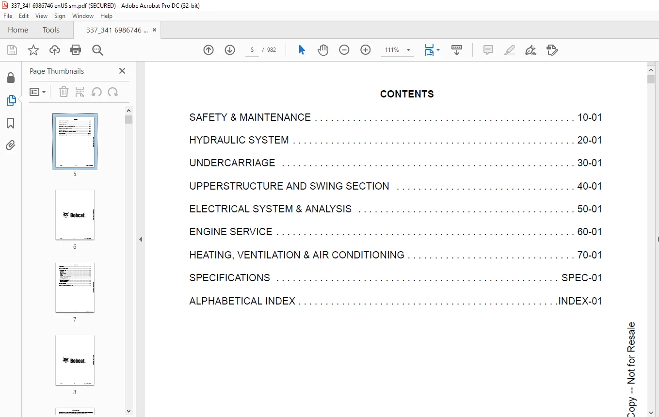
TABLE OF CONTENTS:
Bobcat 337, 341 Compact Excavator Service Manual 6986746 (10-11) – PDF DOWNLOAD
MAINTENANCE SAFETY 3
CONTENTS 5
FOREWORD 7
FOREWORD 9
SAFETY INSTRUCTIONS 12
FIRE PREVENTION 14
Maintenance 14
Operation 14
Electrical 14
Hydraulic System 14
Fueling 14
Starting 14
Spark Arrester Exhaust System 14
Welding And Grinding 15
Fire Extinguishers 15
SERIAL NUMBER LOCATIONS 16
Excavator Serial Number 16
Engine Serial Number 16
DELIVERY REPORT 17
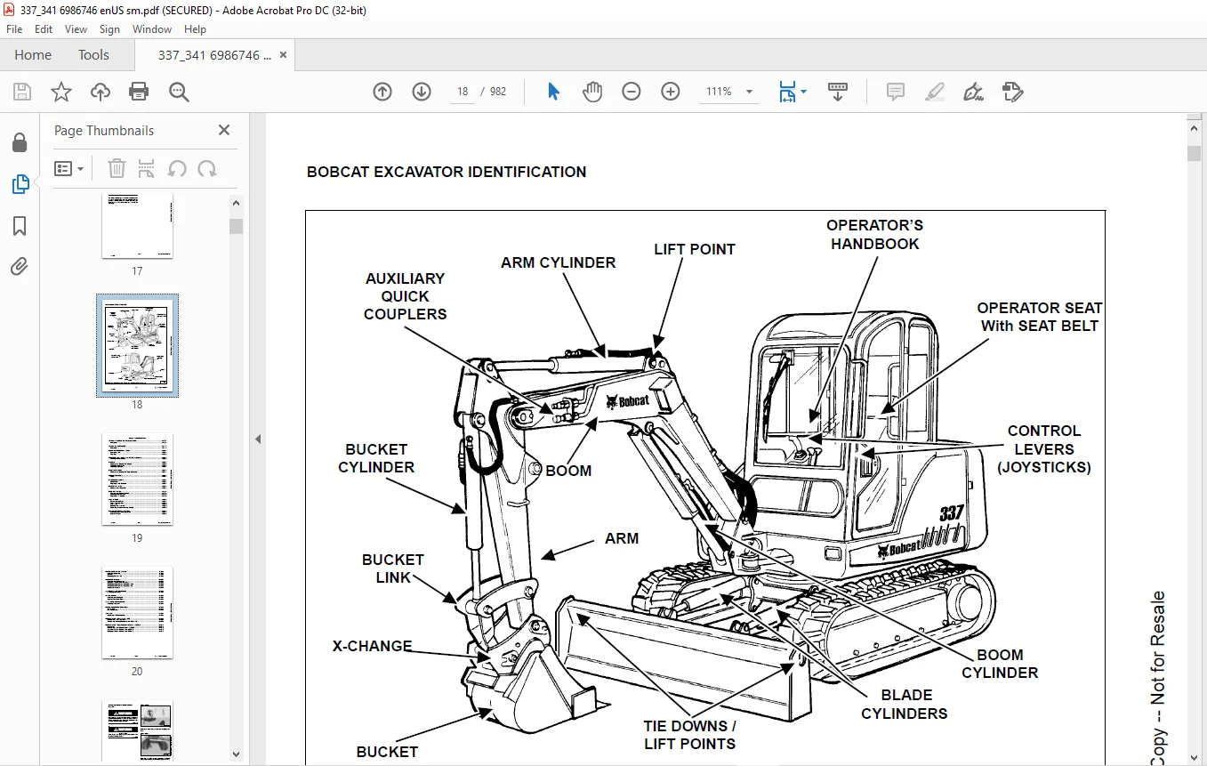
BOBCAT EXCAVATOR IDENTIFICATION 18
SAFETY & MAINTENANCE 19
LIFTING AND BLOCKING THE EXCAVATOR 21
Procedure 21
LIFTING THE EXCAVATOR 23
Procedure 23
OPERATOR CAB (ROPS / TOPS) 25
Emergency Exit 25
Cab Door 26
TRANSPORTING THE EXCAVATOR ON A TRAILER 27
Loading And Unloading 27
TAILGATE 29
Opening And Closing The Tailgate 29
Adjusting The Bumper 29
Adjusting The Latch 29
RIGHT SIDE COVER 31
Opening And Closing The Right Side Cover 31
SERVICE SCHEDULE 33
Chart 33
AIR CLEANER SERVICE 35
Daily Check 35
Replacing Filter Elements 35
HEATER AIR FILTER 37
Removal And Installation 37
COOLING SYSTEM 39
Cleaning The Cooling System 39
Checking Coolant Level 40
Replacing The Coolant 41
FUEL SYSTEM 43
Biodiesel Blend Fuel 43
Filling The Fuel Tank 44
Fuel Filters 44
Draining The Fuel Tank 45
Removing Air From The Fuel System 45
ENGINE LUBRICATION SYSTEM 46
Checking And Adding Engine Oil 46
Engine Oil Chart 46
ENGINE LUBRICATION SYSTEM 47
Checking Engine Oil 47
Oil Chart 47
Replacing Oil And Filter 48
HYDRAULIC SYSTEM 49
Checking And Adding Fluid 49
Hydraulic / Hydrostatic Fluid Chart 50
Removing And Replacing Hydraulic Filters 51
Removing And Replacing Hydraulic Fluid 52
Diagnostic Couplers 53
LUBRICATING THE EXCAVATOR 55
Lubrication Locations 55
TRAVEL MOTOR 59
Checking And Adding Oil 59
Draining The Travel Motor 59
SPARK ARRESTER MUFFLER 61
Cleaning Procedure 61
ENGINE ACCESSORY DRIVE BELT 63
Belt Tension 63
Belt Adjustment 63
SEAT BELT 65
Inspection And Maintenance 65
REMOTE START TOOL KIT – MEL1563 67
Remote Start Tool – MEL1563 67
Service Tool Harness Communicator – MEL1566 69
REMOTE START TOOL (SERVICE TOOL) KIT – 7003031 71
Description 71
Remote Start Tool (Service Tool) – 7003030 72
Excavator Service Tool Harness – 6689747 73
Computer Service Tool Harness – 6689746 74
HYDRAULIC SYSTEM 75
HYDRAULIC / HYDROSTATIC SCHEMATIC 81
HYDRAULIC SYSTEM INFORMATION 83
Glossary Of Hydraulic / Hydrostatic Symbols For Excavators 83
Troubleshooting The Hydraulic Circuit 86
Troubleshooting The Cylinder Circuit 87
Troubleshooting The Upperstructure Slew Circuit 88
Troubleshooting The Travel Circuit 89
Description 90
BOOM CYLINDER 93
Testing 93
Removal And Installation 95
Parts Identification 97
Disassembly 98
Assembly 102
ARM CYLINDER 107
Testing 107
Removal and Installation 109
Parts Identification 111
Disassembly 112
Assembly 115
BOOM SWING CYLINDER 119
Testing 119
Removal And Installation 120
Parts Identification 122
Disassembly 123
Assembly 126
BUCKET CYLINDER 131
Testing 131
Removal And Installation 133
Parts Identification 134
Disassembly 135
Assembly 137
BLADE CYLINDER 141
Testing 141
Removal And Installation 142
Parts Identification 143
Disassembly 144
Assembly 146
CLAMP CYLINDER 149
Testing 149
Removal And Installation 150
Parts Identification 151
Disassembly 152
Assembly 155
ANGLE BLADE CYLINDER 159
Testing 159
Removal And Installation 161
Parts Identification 163
Disassembly 164
Assembly 166
MAIN RELIEF VALVE 169
PORT RELIEF VALVES 171
Port Relief Valve Pressure Setting 171
Parts Identification 171
Adjustment Procedure 172
CROSSPORT RELIEF VALVE 173
Testing And Adjusting The Crossport Relief Valve 173
Removal And Installation 176
Parts Identification 177
Disassembly And Assembly 178
PRESSURE REDUCING VALVE 183
Description 183
ANGLE BLADE VALVE 185
Description 185
Testing And Adjusting Port Relief Valves 185
Testing And Adjusting Sequence Valve 187
Removal And Installation 189
Parts Identification 192
Disassembly 193
Assembly 206
HYDRAULIC CONTROL VALVE 219
Removal And Installation 219
Parts Identification 223
Disassembly And Assembly 224
Slew Valve Section 225
Boom Swing Valve Section 234
Blade Valve Section 241
Bucket Valve Section 252
Arm Valve Section 258
Boom Valve Section 264
Auxiliary Valve Section 270
Right Travel Valve Section 278
Left Travel Valve Section 282
Inlet Section 286
HYDRAULIC PUMP 291
Hydraulic Pump Work Sheet 291
Pump Testing 294
Removal And Installation 306
Coupler Removal And Installation 307
Hydraulic Pump Start Up 308
Torque Limiter Assembly Parts Identification 309
Torque Limiter Valve Assembly Removal And Installation 310
Torque Limiter Valve Assembly Disassembly And Assembly 310
Pump Control Parts Identification 311
Pump Control Removal And Installation 312
Pump Control Disassembly And Assembly 312
Parts Identification 318
Disassembly And Assembly 319
MANIFOLD ASSEMBLY / ACCUMULATOR 327
Description 327
Testing Pilot Pressure 327
Adjusting The Pilot Pressure 329
Removal And Installation 330
Manifold Assembly / Accumulator Parts Identification 333
Disassembly And Assembly 334
TRAVEL MOTOR 345
Removal And Installation 345
Parts Identification 346
Disassembly 347
Assembly 357
SWIVEL JOINT 369
Removal And Installation 369
Parts Identification 370
Disassembly 371
Assembly 372
SWING MOTOR 377
Removal And Installation 377
Parts Identification 381
Disassembly 382
Inspection 386
Assembly 387
SWING MOTOR DRIVE CARRIER 393
Removal And Installation 393
Parts Identification 395
Checking The Drive Carrier Shaft End Play 396
Disassembly 397
Inspection 399
Assembly 400
CONTROL PATTERN SELECTOR VALVE 405
Removal And Installation 405
Parts Identification 406
Disassembly 407
Assembly 408
RIGHT CONTROL LEVER (JOYSTICK) 409
Testing 409
Handle Removal And Installation 411
Joystick Assembly Removal And Installation 415
Parts Identification 418
Disassembly 419
Assembly 424
LEFT CONTROL LEVER (JOYSTICK) 429
Testing 429
Handle Removal And Installation 431
Joystick Assembly Removal And Installation 434
Parts Identification 436
Disassembly 437
Assembly 442
TRAVEL CONTROL VALVE 447
Removal and Installation 447
Parts Identification 449
Disassembly And Assembly 450
HYDRAULIC FILTER MOUNT 453
Removal And Installation 453
HYDRAULIC RESERVOIR 455
Removal And Installation 455
OIL COOLER 459
Removal And Installation 459
DUAL SEQUENCE VALVE 461
Removal And Installation 461
Parts Identification 463
Disassembly And Assembly 464
DIRECT TO TANK VALVE 467
Removal And Installation 467
Parts Identification 468
Disassembly And Assembly 469
BUILD UP VALVE 471
Removal And Installation 471
Parts Identification 472
Disassembly And Assembly 473
CASE DRAIN FILTER MOUNT 477
Removal And Installation 477
REMOVING AIR FROM HYDRAULIC SYSTEM 479
Procedure 479
BOOM SWING LOCK VALVE 481
Description 481
Removal And Installation 481
Parts Identification 483
Disassembly 484
Assembly 487
HYDRAULIC X-CHANGE VALVE 491
Removal And Installation 491
Parts Identification 495
Disassembly 496
Assembly 504
UNDERCARRIAGE 511
BLADE 513
Removal And Installation 513
TRACKS 515
Track Lug Height 515
Rubber Track Clearance 516
Rubber Track Adjustment 517
Steel Track Clearance 518
Steel Track Adjustment 519
Rubber Track Removal And Installation 520
Steel Track Removal 523
Steel Track Installation 525
Track Shoe Removal And Installation 527
TRACK FRAME 529
Disassembly And Assembly 529
Recoil Spring Cylinder Disassembly And Assembly 532
Cylinder Parts Identification (S/N AAC811571 & Below, A9W711150 & Below And A9W911149 & Below) 533
Recoil Spring Cylinder Disassembly And Assembly (S/N AAC811571 & Below, A9W711150 & Below And A9W911149 & Below) 534
Cylinder Parts Identification (S/N AAC811572 & Above, A9W711151 & Above And A9W911150 & Above) 536
Recoil Spring Cylinder Disassembly And Assembly (S/N AAC811572 & Above, A9W711151 & Above And A9W911150 & Above) 537
TRACK DAMAGE IDENTIFICATION 539
Cutting Of Steel Cords 539
Abrasion Of Embedded Metals 540
Separation Of Embedded Metals 541
Separation Of Embedded Metals Due To Corrosion 542
Cuts On The Lug Side Rubber 543
Cracks On The Lug Side Rubber Due To Fatigue 544
Lug Abrasion 545
Cracks And Cuts On The Lug Side Rubber 546
Abrasion Of The Track Roller Side 547
Cuts On The Edges Of Track Roller Side 548
TRACK IDLER 551
Parts Identification 551
Disassembly 552
Assembly 554
TRACK ROLLER 557
Parts Identification (Upper Roller) 557
Disassembly (Upper Roller) 558
Assembly (Upper Roller) 560
Parts Identification (Lower Roller) 562
Disassembly (Lower Roller) 563
Assembly (Lower Roller) 565
SWING CIRCLE GEAR 567
Swing Bearing Removal 567
Swing Bearing Installation 568
UPPERSTRUCTURE AND SWING SECTION 569
UPPERSTRUCTURE 573
Removal 573
Installation 576
ANGLE BLADE ASSEMBLY 579
Removal And Installation 579
ANGLE BLADE 581
Removal And Installation 581
ANGLE BLADE CUTTING EDGE 583
Removal And Installation 583
ROPS CANOPY 585
Removal And Installation 585
CAB 589
Removal And Installation 589
Door Removal And Installation 594
Front Window Removal And Installation 595
Right Side Rear Sliding Window Removal And Installation 598
Right Side Front Sliding Window Removal And Installation 598
Right Side Front And Rear Sliding Window Weather Strip Removal And Installation 599
Right Side Front And Rear Sliding Window Wiper Strip Removal And Installation 599
Glass Removal 600
Glass Installation 601
SEAT AND SEAT MOUNT 603
Removal And Installation 603
RIGHT CONSOLE 605
Console Cover Removal And Installation 605
Console Base Removal And Installation 606
LEFT CONSOLE 609
Lower Console Cover Removal And Installation 609
Upper Console Cover Removal And Installation 610
Compression Spring Removal And Installation 611
Compression Spring Disassembly And Assembly 612
Lock Lever Removal And Installation 613
Console Removal And Installation 615
Disassembly And Assembly 620
Console Switch Removal And Installation 623
Console Base Removal And Installation 624
ENGINE SPEED CONTROL 625
Removal And Installation 625
Adjustment (Later Models) 626
BLADE CONTROL 627
Lever Removal And Installation 627
Linkage Removal And Installation 628
Linkage Disassembly And Assembly 629
Linkage Bar Removal And Installation 631
Lower Linkage Removal And Installation 632
Lower Linkage Disassembly And Assembly 634
RIGHT PEDAL AND LINKAGE 637
Pedal Removal And Installation 637
Pedal Disassembly And Assembly 638
Lower Linkage Removal And Installation 640
Lower Linkage Disassembly And Assembly 642
Bellcrank Removal And Installation 643
TRAVEL CONTROLS 645
Removal And Installation 645
Disassembly And Assembly 646
Adjustment 648
CONTROL LINKAGE ASSEMBLY 651
Removal And Installation 651
FLOOR MAT AND FLOOR PLATE 653
Removal And Installation 653
FUEL TANK 655
Removal And Installation 655
HORN 657
Removal And Installation 657
SWING FRAME 659
Boom Swing Bracket Removal And Installation 659
Boom Swing Bracket Hose Installation 663
Swing Bracket Bushing Removal 664
Swing Bracket Bushing Installation 665
Boom Pivot Pin Bushing Removal 666
Boom Pivot Pin Bushing Installation 667
BOOM 669
Removal And Installation 669
Boom Pivot Pin Bushing Removal And Installation 670
ARM 671
Removal And Installation 671
BUCKET 673
Bucket Teeth Removal And Installation 673
CLAMP 675
Removal And Installation 675
TAILGATE 677
Removal And Installation 677
Latch Removal And Installation 678
Striker Removal And Installation 679
X-CHANGE 681
Removal And Installation 681
Parts Identification 683
Disassembly 684
Assembly 689
Check Proper Latch Engagement 695
X-CHANGE (PIN ON) 699
Removal And Installation 699
Parts Identification 701
Disassembly And Assembly 702
X-CHANGE (HYDRAULIC) 703
Removal And Installation 703
Parts Identification 706
Disassembly 707
Assembly 712
QUICK COUPLER (KLAC™ SYSTEM) 721
Troubleshooting 721
Daily Inspection 721
Removal And Installation 722
Parts Identification 724
Disassembly 725
Assembly 726
QUICK COUPLER (LEHNHOFF® SYSTEM) 729
Troubleshooting 729
Daily Inspection 729
Removal (MS03 And MS08) 730
Installation (MS03 And MS08) 731
Parts Identification (MS03) 732
Disassembly And Assembly (MS03) 733
Parts Identification (MS08) 734
Disassembly (MS08) 735
Assembly (MS08) 738
ELECTRICAL SYSTEM & ANALYSIS 743
ELECTRICAL SCHEMATICS 745
ELECTRICAL SYSTEM INFORMATION 747
Troubleshooting Chart 747
Description 748
Fuse And Relay Location 748
BATTERY 749
Servicing 749
Removing And Installing The Battery 750
Using A Booster Battery (Jump Starting) 751
ALTERNATOR 753
Engine Accessory Drive Belt 753
Removal And Installation 753
Alternator Identification 755
Charging System Check 756
Alternator Voltage Test 757
Low Voltage Test 757
High Voltage Test 758
Rectifier Continuity (Diode) Test 759
Alternator Regulator Test 760
Parts Identification 761
Disassembly 762
Stator Continuity Test 762
Stator Ground Test 763
Rotor Continuity Test 763
Rotor Ground Test 763
Assembly 763
STARTER 765
Removal And Installation 765
Parts Identification 766
Disassembly 767
Inspection And Repair 772
Assembly 775
LIGHTS 781
Removal And Installation 781
Disassembly And Assembly 782
TWO-SPEED SWITCH 783
Removal And Installation 783
FUEL LEVEL SENDER 785
Removal And Installation 785
Testing And Inspection 786
DIAGNOSTICS SERVICE CODE 787
Number Codes List 787
DELUXE INSTRUMENT PANEL SETUP 789
Passwords 789
Password Entry (For Starting And Operating The Machine) 789
Changing The Owner or Operator Password 789
Password Lockout Feature 790
Job Clock 790
RPM 790
ENGINE SERVICE 791
TROUBLESHOOTING 793
Chart 793
MUFFLER 795
Removal And Installation 795
AIR CLEANER 797
Removal And Installation 797
RADIATOR 799
Removal And Installation 799
ENGINE COMPONENTS AND TESTING 801
Engine Compression Checking 801
Glow Plugs Removal And Installation 802
Checking The Glow Plug 803
Fuel Shut-off Solenoid Removal And Installation 803
Fuel Injection Pump Check 804
Fuel Injection Pump Removal And Installation 804
Fuel Injection Pump Timing 808
Fuel Injector Nozzles Removal And Installation 810
Fuel Injector Nozzle Check 813
Valve Clearance Adjustment 814
ENGINE 815
Removal And Installation 815
ENGINE FLYWHEEL 821
Flywheel Removal And Installation 821
Hydraulic Pump Coupler 823
Flywheel Ring Gear 823
RECONDITIONING THE ENGINE 825
Cylinder Head Removal And Installation 825
Cylinder Head Disassembly And Assembly 828
Cylinder Head Servicing 829
Cylinder Head Top Clearance 829
Valve Guide Checking 830
Reconditioning The Valve And Valve Seat 832
Valve Spring 833
Rocker Arm And Shaft Checking 834
Timing Gearcase Cover Removal And Installation 835
Idler Gear And Camshaft Removal And Installation 838
Camshaft Servicing 839
Idler Gear And Shaft Servicing 840
Timing Gears Checking Backlash 841
Fuel Camshaft Removal And Installation 841
Fuel Camshaft Governor 842
Crankshaft Gear Removal And Installation 842
Oil Pump Removal And Installation 843
Oil Pump Service 843
Checking Engine Oil Pressure 844
Valve Tappets 845
Piston And Connecting Rod Removal And Installation 845
Piston And Connecting Rod Servicing 847
Connecting Rod Alignment 849
Crankshaft And Bearings Removal And Installation 850
Crankshaft And Bearings, Servicing 852
Cylinder Bore, Checking 856
Water Pump Removal And Installation 856
Water Pump Disassembly And Assembly 857
Fan Removal And Installation 857
HEATING, VENTILATION & AIR CONDITIONING 859
HEATER COIL 861
Removal And Installation With A/C 861
Removal And Installation Without A/C 861
BLOWER FAN 863
Removal And Installation 863
Disassembly And Assembly 864
Resistor Removal And Installation 865
HEATER VALVE 867
Removal And Installation 867
AIR CONDITIONING SYSTEM FLOW 871
Principals 871
Chart 872
COMPONENTS 873
Identification 873
SAFETY 877
Safety Equipment 877
REGULAR MAINTENANCE 879
Heater Air Filter 879
Engine Accessory Drive Belt Inspection 879
Cleaning The Condenser 880
BASIC TROUBLESHOOTING 881
Poor A/C Performance 881
Cleaning The A/C Evaporator Coil And Heater Coil 882
Engine Accessory Drive Belt Inspection 883
Checking The Electrical System 884
Engine Coolant Bypassing The Heater Valve 894
GENERAL AIR CONDITIONING SERVICE GUIDELINES 895
Compressor Oil 895
Compressor Oil Check 896
Component Replacement And Refrigeration Leaks 898
SYSTEM TROUBLESHOOTING CHART 899
Blower Motor Does Not Operate 899
Gauge Pressure Related Troubleshooting 900
TEMPERATURE / PRESSURE 903
Chart 903
AIR CONDITIONING SERVICE 905
Chart 905
SYSTEM CHARGING AND RECLAMATION 907
Reclamation Procedure 907
Charging Procedure With A Manifold Gauge Set 910
COMPRESSOR 913
Removal And Installation 913
Compressor Clutch Disassembly And Assembly 915
CONDENSER 919
Removal And Installation 919
RECEIVER / DRIER 921
Removal And Installation 921
PRESSURE RELIEF VALVE 923
Removal And Installation 923
PRESSURE SWITCH 925
Removal And Installation 925
EVAPORATOR / HEATER UNIT 927
Removal And Installation 927
Disassembly And Assembly 928
THERMOSTAT 929
Removal And Installation 929
EVAPORATOR VALVE 931
Removal And Installation 931
BLOWER FAN 933
Removal And Installation 933
Disassembly And Assembly 934
Resistor Removal And Installation 935
SPECIFICATIONS 937
(337, 341) EXCAVATOR SPECIFICATIONS 939
337 Dimensions 939
337 W / Long Arm And 341 Dimensions 941
337 And 341 With Optional Angle Blade Dimensions 943
Performance 944
Controls 944
Engine 944
Hydraulic System 945
Hydraulic Cylinders 945
Hydraulic Cycle Times 946
Electrical 946
Instrumentation 946
Drive System 946
Slew System 946
Undercarriage 946
Crawler Track Design 946
Capacities 946
Fuel Tank 946
Track 947
Type 947
Ground Pressure 947
ENGINE SPECIFICATIONS 949
Fuel Injection Nozzles 949
Fuel Injection Pump 949
Cylinder Head 949
Valves 949
Valve Springs 950
Valve Timing 950
Rocker Arms 950
Camshaft 950
Tappet 950
Cylinders 951
Piston Rings 951
Pistons 951
Connecting Rods 951
Oil Pump 951
Crankshaft 952
Timing Gear 952
Thermostat 953
Engine Bolt Torque 953
Crankshaft Re-Grind Data 954
TORQUE SPECIFICATIONS 955
Torque for General SAE Bolts 955
Torque For General Metric Bolts 955
HYDRAULIC CONNECTION SPECIFICATIONS 957
O-ring Face Seal Connection 957
Straight Thread O-ring Fitting 957
Tubelines And Hoses 957
Flare Fitting 958
O-ring Flare Fitting 959
Port Seal Fitting 961
HYDRAULIC FLUID SPECIFICATIONS 963
Specifications 963
FUEL, COOLANT AND LUBRICANTS 965
Chart 965
CONVERSIONS 967
Decimal And Millimeter Equivalents 967
U S To Metric Conversion Chart 967
ALPHABETICAL INDEX 969
SERVICE MANUAL REVISION 971
Revision No: 337 / 341 – 1 971
Revision No: 337 / 341 – 2 973
Revision No: 337 / 341 – 3 975
Revision No: 337 / 341 – 4 977
Revision No: 337 / 341 – 5 979
Revision No: 337, 341 – 6 981
IMAGES PREVIEW OF THE MANUAL:
Contact us: [email protected]
https://vimeo.com/840707268?share=copy
PLEASE NOTE:
- This is the SAME exact manual used by your dealers to fix your vehicle.
- The same can be yours in the next 2-3 mins as you will be directed to the download page immediately after paying for the manual.
- Any queries / doubts regarding your purchase, please feel free to contact [email protected]
s.m