Bobcat 430 Compact Excavator Service Manual 6902318 (07-14) – PDF DOWNLOAD
$35.95
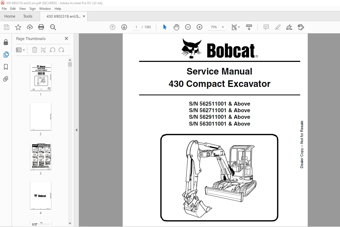
Bobcat 430 Compact Excavator Service Manual 6902318 (07-14) – PDF DOWNLOAD
S/N 562511001 & Above
S/N 562711001 & Above
S/N 562911001 & Above
S/N 563011001 & Above
Description
Bobcat 430 Compact Excavator Service Manual 6902318 (07-14) – PDF DOWNLOAD
FILE DETAILS:
Bobcat 430 Compact Excavator Service Manual 6902318 (07-14) – PDF DOWNLOAD
Language : English
Pages :1393
Downloadable : Yes
File Type : PDF
Size: 55.8 MB
DESCRIPTION:
Bobcat 430 Compact Excavator Service Manual 6902318 (07-14) – PDF DOWNLOAD
S/N 562511001 & Above
S/N 562711001 & Above
S/N 562911001 & Above
S/N 563011001 & Above
FOREWORD:
This manual is for the Bobcat loader mechanic. It provides necessary servicing and adjustment procedures for the Bobcat loader and its component parts and systems. Refer to the Operation & Maintenance Manual for operating instructions, Starting procedure, daily checks, etc.
The following publications provide information on the safe use and maintenance of the Bobcat machine and attachments:
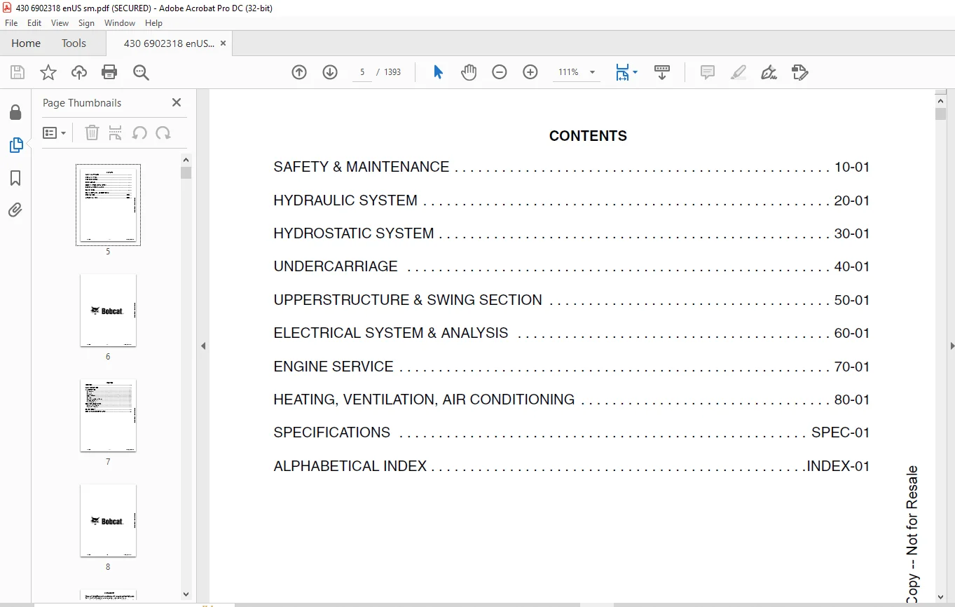
TABLE OF CONTENTS:
Bobcat 430 Compact Excavator Service Manual 6902318 (07-14) – PDF DOWNLOAD
MAINTENANCE SAFETY 3
CONTENTS 5
FOREWORD 7
FOREWORD 9
SAFETY INSTRUCTIONS 11
FIRE PREVENTION 13
Maintenance 13
Operation 13
Electrical 13
Hydraulic System 13
Fueling 13
Starting 13
Spark Arrester Exhaust System 13
Welding And Grinding 14
Fire Extinguishers 14
SERIAL NUMBER LOCATIONS 15
Excavator Serial Number 15
Engine Serial Number 15
DELIVERY REPORT 16
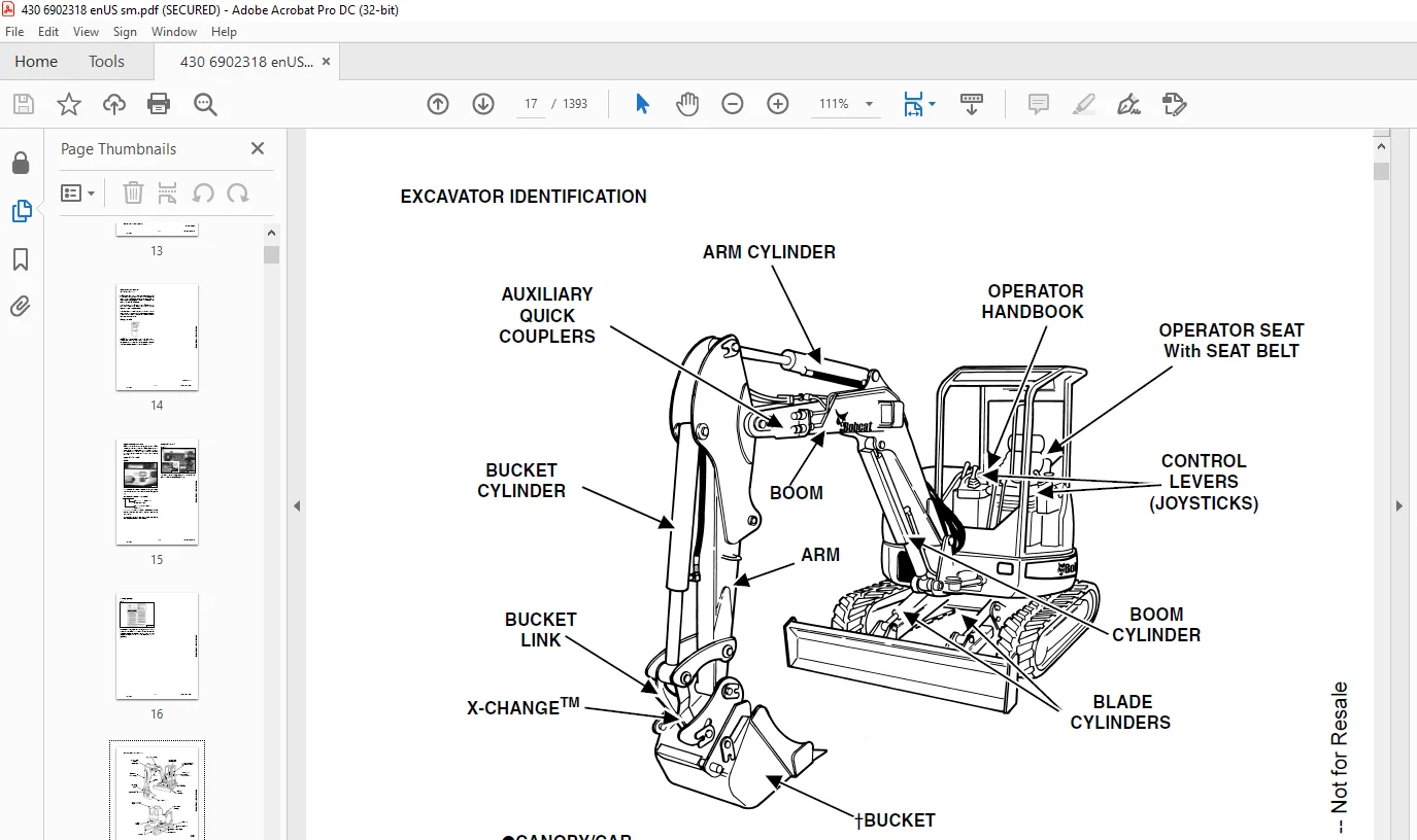
EXCAVATOR IDENTIFICATION 17
SAFETY & MAINTENANCE 19
LIFTING AND BLOCKING THE EXCAVATOR 23
Procedure 23
UPPERSTRUCTURE SLEW LOCK 25
Operation 25
LIFTING THE EXCAVATOR 27
Procedure 27
OPERATOR CAB (ROPS / TOPS) 29
Description 29
Cab Door 29
Front Window 30
Front Window 31
Right Side Window (Early Models) 32
Right Side Window (Later Models) 33
Heating, Ventilation, and Air Conditioning Duct 34
TRANSPORTING THE EXCAVATOR ON A TRAILER 35
Loading And Unloading 35
Fastening 35
TAILGATE 37
Opening And Closing The Tailgate 37
Adjusting The Latch 37
RIGHT SIDE COVER 39
Opening And Closing 39
SERVICE SCHEDULE 41
Chart 41
AIR CLEANER SERVICE 43
Daily Check 43
Replacing The Filters 43
HEATER AIR FILTER (WITH CAB OPTION ONLY) 45
Removal And Installation 45
ENGINE COOLING SYSTEM 47
Cleaning 47
Checking Level 48
Removing And Replacing Coolant 49
FUEL SYSTEM 51
Fuel Specifications 51
Biodiesel Blend Fuel 51
Filling The Fuel Tank 52
Removing Water 52
Replacing Element 52
Draining The Fuel Tank 53
Inline Fuel Filter 53
Removing Air From The Fuel System 53
ENGINE LUBRICATION SYSTEM 55
Checking And Adding Engine Oil 55
Engine Oil Chart 55
Removing And Replacing Oil Filter 56
HYDRAULIC SYSTEM 57
Checking And Adding Fluid 57
Hydraulic Fluid Chart 57
Removing And Replacing The Hydraulic Fluid 58
Removing And Replacing The Hydraulic Filter 59
Removing And Replacing The Case Drain Filter 59
Removing And Replacing The Fan Filter 60
Diagnostic Couplers 60
LUBRICATING THE EXCAVATOR 61
Lubrication Locations 61
TRAVEL MOTOR 65
Checking And Adding Oil Level 65
Removing And Replacing Oil 65
SPARK ARRESTOR MUFFLER 67
Cleaning Procedure 67
ENGINE ACCESSORY DRIVE BELT 69
Belt Tension 69
Belt Adjustment 69
SEAT BELT 71
Inspection And Maintenance 71
PIVOT PINS 73
Inspection And Maintenance 73
EXCAVATOR STORAGE AND RETURN TO SERVICE 75
Storage 75
Return To Service 75
STOPPING THE ENGINE AND LEAVING THE EXCAVATOR 77
Procedure 77
Emergency Exits 78
MOTION ALARM SYSTEM (IF EQUIPPED) 79
Description 79
Inspecting 79
Adjusting Switch Position 79
HYDRAULIC SYSTEM 81
HYDRAULIC/HYDROSTATIC SCHEMATICS 89
HYDRAULIC SYSTEM INFORMATION 101
Glossary Of Hydraulic / Hydrostatic Symbols 101
Troubleshooting The Hydraulic Circuit 105
Troubleshooting The Cylinder Circuit 105
Troubleshooting The Upperstructure Slew Circuit 106
BOOM CYLINDER 107
Testing 107
Removal And Installation 110
Parts Identification 113
Disassembly 114
Assembly 116
ARM CYLINDER 119
Testing 119
Removal And Installation 121
Parts Identification 123
Disassembly 124
Assembly 126
BOOM SWING CYLINDER 129
Testing 129
Removal And Installation 130
Parts Identification 132
Disassembly 133
Assembly 135
BUCKET CYLINDER 139
Testing 139
Removal And Installation 141
Parts Identification 143
Disassembly 144
Assembly 146
BLADE CYLINDER 151
Testing 151
Removal And Installation 152
Parts Identification 153
Disassembly 154
Assembly 156
CLAMP CYLINDER 159
Testing 159
Removal And Installation 160
Parts Identification 161
Disassembly 162
Assembly 165
ANGLE BLADE CYLINDER 169
Testing 169
Removal And Installation 170
Parts Identification 172
Disassembly 173
Assembly 175
MAIN RELIEF VALVES 179
Testing And Adjusting The Main Relief Valves (S/N 562511001 & Above) 179
System Pressures At Gauge Port Specifications 179
Testing And Adjusting The Main Relief Valves (S/N 562711001 & Above) 183
System Pressures At Gauge Port Specifications 183
Testing And Adjusting The Main Relief Valves (S/N 562911001 & Above) 187
System Pressures At Gauge Port Specifications 187
Testing And Adjusting The Main Relief Valves (S/N 563011001 Above) 190
System Pressures At Gauge Port Specifications 190
PORT RELIEF VALVES 193
Testing And Adjusting Port Relief Valve Pressure 193
CROSSPORT RELIEF VALVES 199
Testing And Adjusting The Crossport Relief Valves (S/N 562511001 & Above) 199
Testing And Adjusting The Crossport Relief Valves (S/N 562711001 & Above) 201
Testing And Adjusting The Crossport Relief Valves (S/N 562911001 & Above) 203
Testing And Adjusting The Crossport Relief Valves (S/N 563011001 & Above) 205
PRESSURE REDUCING VALVE 207
Description 207
ANGLE BLADE VALVE 209
Description 209
Testing And Adjusting Port Relief Valves 209
Testing And Adjusting Sequence Valve 211
Removal And Installation 213
Parts Identification 216
Disassembly 217
Assembly 230
HYDRAULIC CONTROL VALVE (S/N 562511001 & ABOVE AND 562711001 & ABOVE) 243
Removal And Installation 243
Parts Identification 244
Disassembly And Assembly 245
Slew Valve Section Disassembly And Assembly 248
Blade Valve Section Disassembly And Assembly 251
Boost Valve Section Disassembly And Assembly 256
Auxiliary Valve Section Disassembly And Assembly 259
Bucket Valve Section Disassembly And Assembly 262
Arm Valve Section Disassembly And Assembly 264
Mid-Inlet Valve Section Disassembly And Assembly 266
Boom Valve Section Disassembly And Assembly 268
HYDRAULIC CONTROL VALVE (S/N 562911001 – 562912778) 277
Description 277
Removal And Installation 278
Parts Identification 281
Disassembly 282
Right Travel Valve Section Disassembly And Assembly 283
Left Travel Valve Section Disassembly And Assembly 287
Blade Valve Section Disassembly And Assembly 291
Slew Valve Section Disassembly And Assembly 299
Second Auxiliary Valve Section Disassembly And Assembly 304
Bucket Valve Section Disassembly And Assembly 308
Arm Valve Section Disassembly And Assembly 312
Boom Valve Section Disassembly And Assembly 317
Boom Swing Valve Section Disassembly And Assembly 321
First Auxiliary Valve Section Disassembly And Assembly 326
Inlet Section Disassembly And Assembly 331
Assembly 336
HYDRAULIC CONTROL VALVE (S/N 562912779 & Above) 343
Description 343
Removal And Installation 344
Parts Identification 350
Disassembly 351
Right Travel Valve Section Disassembly And Assembly 352
Left Travel Valve Section Disassembly And Assembly 356
Blade Valve Section Disassembly And Assembly 360
Slew Valve Section Disassembly And Assembly 368
Auxiliary Valve Section Disassembly And Assembly 373
Bucket Valve Section Disassembly And Assembly 377
Arm Valve Section Disassembly And Assembly 382
Boom Valve Section Disassembly And Assembly 386
Boom Swing Valve Section Disassembly And Assembly 391
Inlet Section Disassembly And Assembly 396
Assembly 401
HYDRAULIC CONTROL VALVE (S/N 563011001 – 563012775) 407
Description 407
Removal And Installation 407
Parts Identification 408
Disassembly 409
Blade Valve Section Disassembly And Assembly 410
Slew Valve Section Disassembly And Assembly 418
Second Auxiliary Valve Section Disassembly And Assembly 423
Bucket Valve Section Disassembly And Assembly 427
Arm Valve Section Disassembly And Assembly 431
Boom Valve Section Disassembly And Assembly 436
Boom Swing Valve Section Disassembly And Assembly 440
First Auxiliary Valve Section Disassembly And Assembly 445
Inlet Section Disassembly And Assembly 450
Assembly 455
HYDRAULIC CONTROL VALVE (S/N 563012776 & ABOVE) 461
Description 461
Removal And Installation 462
Parts Identification 465
Disassembly 466
Blade Valve Section Disassembly And Assembly 467
Slew Valve Section Disassembly And Assembly 475
Auxiliary Valve Section Disassembly And Assembly 480
Bucket Valve Section Disassembly And Assembly 484
Arm Valve Section Disassembly And Assembly 489
Boom Valve Section Disassembly And Assembly 493
Boom Swing Valve Section Disassembly And Assembly 498
Inlet Section Disassembly And Assembly 503
Assembly 508
HYDRAULIC PUMP (S/N 562511001 & ABOVE AND 562711001 & ABOVE) 513
Description 513
Torque Adjustment 514
Testing The Piston Pump 515
Testing The Gear Pump 517
Testing Auxiliary Flow 519
Removal And Installation 520
Coupler Removal And Installation 521
Hydraulic Pump Start Up 522
Gear Pump Parts Identification 523
Piston Pump Parts Identification 524
Disassembly 525
Gear Pump Disassembly 527
Gear Pump Assembly 530
Piston Pump Disassembly 533
Piston Pump Assembly 541
Assembly 549
HYDRAULIC PUMP (S/N 562911001 & ABOVE AND 563011001 & ABOVE) 551
Description 551
Torque Adjustment 552
Testing The Piston Pump 553
Testing The Gear Pump 555
Testing Auxiliary Flow 557
Removal And Installation 558
Coupler Removal And Installation 559
Hydraulic Pump Start Up 560
Gear Pump Parts Identification 561
Piston Pump Parts Identification 562
Disassembly 563
Gear Pump Disassembly 564
Gear Pump Assembly 567
Piston Pump Disassembly 570
Piston Pump Assembly 576
Assembly 583
MANIFOLD ASSEMBLY / ACCUMULATOR (S/N 562511001 & ABOVE, 562711001 & ABOVE AND 563011001 & ABOVE) 585
Description 585
Testing Pilot Pressure 586
Removal And Installation 587
Parts Identification 589
Disassembly 590
Assembly 601
MANIFOLD ASSEMBLY / ACCUMULATOR (S/N 562911001 & ABOVE) 613
Description 613
Testing Pilot Pressure 614
Removal And Installation 615
Parts Identification 617
Disassembly 618
Assembly 627
TRAVEL MOTOR (S/N 562511001 & ABOVE, 562711001 & ABOVE AND 563011001 & ABOVE) 637
Removal And Installation 637
Parts Identification 639
Disassembly 640
Assembly 654
TRAVEL MOTOR (S/N 562911001 THROUGH 562912751) 671
Removal And Installation 671
Parts Identification 673
Disassembly 674
Assembly 688
TRAVEL MOTOR (S/N 562912752 & Above) 703
Description 703
Removal And Installation 703
Parts Identification 704
Disassembly 705
Assembly 715
SWIVEL JOINT 727
Removal And Installation 727
Parts Identification 729
Description 730
Disassembly 730
Assembly 733
SWING MOTOR 737
Removal And Installation 737
Parts Identification 739
Disassembly 740
Assembly 745
SWING MOTOR DRIVE CARRIER 751
Removal And Installation 751
Parts Identification 752
Disassembly 753
Assembly 755
CONTROL PATTERN SELECTOR VALVE 757
Removal And Installation 757
Parts Identification 758
Disassembly 759
Assembly 760
RIGHT CONTROL LEVER (JOYSTICK) 761
Testing 761
Handle Removal And Installation 762
Joystick Assembly Removal And Installation 766
Parts Identification 769
Disassembly 770
Assembly 774
LEFT CONTROL LEVER (JOYSTICK) 779
Testing 779
Handle Removal And Installation 781
Joystick Assembly Removal And Installation 784
Parts Identification 786
Disassembly 787
Assembly 792
TRAVEL CONTROL VALVE (S/N 562511001 & ABOVE, 562711001 & ABOVE AND 563011001 & ABOVE) 797
Removal and Installation 797
Parts Identification 798
Disassembly And Assembly 799
TRAVEL CONTROL VALVE (S/N 562911001 & ABOVE) 805
Removal And Installation 805
Parts Identification 806
Disassembly And Assembly 807
HOSES 811
Hose Guide Location 811
Left Control Lever (Joystick) (S/N 562911001 & Above) (Later Models) 812
Left Control Lever (Joystick) (S/N 563011001 & Above) (Later Models) 813
Right Control Lever (Joystick) (S/N562911001 And Above) (Later Models) 814
Right Control Lever (Joystick) (S/N 563011001 & Above) (Later Models) 815
Travel Control Valve (S/N 562911001 & Above) (Later Models) 816
Travel Control Valve (S/N A563011001 & Above) (Later Models) 817
Manifold Assembly / Accumulator (S/N 562911001 & Above) (Later Models) 818
Manifold Assembly / Accumulator (S/N 563011001 & Above) (Later Models) 819
HYDRAULIC FILTER MOUNT 821
Removal And Installation 821
HYDRAULIC RESERVOIR 823
Removal And Installation 823
OIL COOLER 825
Removal And Installation 825
DIRECT TO TANK VALVE (IF EQUIPPED) 829
Removal And Installation 829
Parts Identification 830
Disassembly And Assembly 831
BUILD UP VALVE 833
CASE DRAIN FILTER 835
Removal And Installation 835
COOLING FAN 837
Description 837
Testing 837
Removal And Installation 838
Parts Identification 840
Disassembly And Assembly 841
BOOM SWING LOCK VALVE 849
Description 849
Removal And Installation 849
Parts Identification 850
Disassembly 851
Assembly 854
HYDRAULIC X-CHANGE™ VALVE 859
Removal And Installation 859
Parts Identification 862
Disassembly 863
Assembly 870
HYDROSTATIC SYSTEM 877
HYDROSTATIC SYSTEM INFORMATION 879
Troubleshooting Chart 879
Relief / Replenishing Valve Function 880
Relief / Replenishing Valve Location 881
Relief / Replenishing Valve Removal And Installation 881
Charge Pressure Relief Valve Removal And Installation 882
TRAVEL PILOT PRESSURE 883
Description 883
Testing 883
HYDROSTATIC PUMP 885
Removal And Installation 885
Fan / Charge Pump Parts Identification 888
Fan / Charge Pump Disassembly And Assembly (S/N 562511001 & Above And 562711001 & Above) 889
Parts Identification (Front) (S/N 562511001 & Above, 562711001 & Above And 563111001 & Above) 894
Parts Identification (Rear) (S/N 562511001 & Above And 562711001 & Above) 895
Parts Identification (Rear) (S/N 563011001 & Above) 896
Disassembly 897
Inspection 908
Assembly 910
Hydrostatic Pump StartUp 922
FAN / CHARGE PUMP 923
Description (S/N 562511001 & Above And 562711001 & Above) 923
Testing 923
DRIVE BELT SHIELD 925
Removal And Installation 925
DRIVE BELT 927
Adjustment 927
Removal And Installation 929
UNDERCARRIAGE 931
BLADE 933
Removal And Installation 933
ANGLE BLADE ASSEMBLY 935
Removal And Installation 935
ANGLE BLADE 937
Removal And Installation 937
ANGLE BLADE CUTTING EDGE 939
Removal And Installation 939
TRACKS 941
Track Lug Height 941
Rubber Track Clearance 942
Steel Track Clearance 943
Adjustment 943
Rubber Track Removal And Installation 944
Steel Track Removal And Installation 947
TRACK FRAME 951
Disassembly And Assembly 951
Recoil Spring Cylinder Disassembly And Assembly (W / O Replaceable Shaft) 952
Recoil Spring Cylinder Parts Identification (With Replaceable Shaft) 955
Recoil Spring Cylinder Disassembly And Assembly (With Replaceable Shaft) 956
TRACK DAMAGE IDENTIFICATION 959
Cutting Of Steel Cords 959
Abrasion Of Embedded Metals 960
Separation Of Embedded Metals 961
Separation Of Embedded Metals Due To Corrosion 962
Cuts On The Lug Side Rubber 963
Cracks On The Lug Side Rubber Due To Fatigue 964
Lug Abrasion 965
Cracks And Cuts On The Lug Side Rubber 966
Abrasion Of The Track Roller Side 967
Cuts On The Edges Of Track Roller Side 968
TRACK IDLER 971
Parts Identification 971
Disassembly 972
Assembly 974
UPPER TRACK ROLLER 977
Parts Identification 977
Disassembly 978
Assembly 980
LOWER TRACK ROLLER 983
Parts Identification 983
Disassembly 984
Assembly 986
SWING CIRCLE GEAR 989
Swing Bearing Removal 989
Swing Bearing Installation 990
UPPERSTRUCTURE & SWING SECTION 991
UPPERSTRUCTURE 995
Removal 995
Installation 997
ROPS CANOPY 999
Removal And Installation 999
CAB 1003
Removal And Installation 1003
Front Window Removal And Installation 1008
Right Side Rear Sliding Window Removal And Installation 1011
Right Side Front Sliding Window Removal And Installation 1011
Right Side Front And Rear Sliding Window Weather Strip Removal And Installation 1012
Right Side Front And Rear Sliding Window Wiper Strip Removal And Installation 1012
Glass Removal 1013
Glass Installation 1014
SEAT AND SEAT MOUNT 1017
Removal And Installation 1017
RIGHT CONSOLE 1019
Console Cover Removal And Installation 1019
Console Base Removal And Installation 1020
LEFT CONSOLE 1023
Lower Console Cover Removal And Installation 1023
Upper Console Cover Removal And Installation 1024
Compression Spring Removal And Installation 1025
Compression Spring Disassembly And Assembly 1026
Lock Lever Removal And Installation 1027
Console Removal And Installation 1028
Disassembly And Assembly 1032
Console Switch Removal And Installation 1035
Console Base Removal And Installation 1036
ENGINE SPEED CONTROL 1037
Removal And Installation 1037
Disassembly And Assembly 1038
Adjustment (Later Models) 1039
BLADE CONTROL 1041
Lever Removal And Installation 1041
Linkage Removal And Installation 1042
Linkage Disassembly And Assembly 1042
Control Cable Removal And Installation 1044
RIGHT PEDAL AND LINKAGE 1045
Pedal Removal And Installation 1045
Pedal Disassembly And Assembly 1046
Control Cable Removal And Installation 1048
TRAVEL CONTROLS 1049
Removal And Installation 1049
Disassembly And Assembly 1052
Adjustment 1054
CONTROL LINKAGE ASSEMBLY 1057
Removal And Installation 1057
FLOOR MAT AND FLOOR PLATES 1059
Removal And Installation 1059
FUEL TANK 1061
Removal And Installation 1061
HORN 1063
Removal And Installation (Earlier Models) 1063
Removal And Installation (Later Models) 1063
SWING FRAME 1065
Boom Swing Bracket Removal And Installation 1065
Boom Swing Bracket Hose Installation 1068
Bushing Removal 1069
Bushing Installation 1070
BOOM 1071
Removal And Installation 1071
ARM 1073
Removal And Installation 1073
Arm To Boom Bushing Removal And Installation 1074
Arm To Bucket And Bucket Link Bushing Removal And Installation 1075
BUCKET 1077
Bucket Teeth Removal And Installation 1077
Bucket Side Cutting Edge Removal And Installation 1078
CLAMP 1079
Removal And Installation 1079
TAILGATE 1081
Removal And Installation 1081
X-CHANGE™ 1083
Removal And Installation 1083
Parts Identification 1085
Disassembly 1086
Assembly 1091
Check Proper Latch Engagement 1097
X-CHANGE™ (HYDRAULIC) 1101
Removal And Installation 1101
Parts Identification 1103
Disassembly 1104
Assembly 1109
UPPERSTRUCTURE SLEW LOCK 1117
Removal And Installation 1117
Disassembly And Assembly 1118
RIGHT SIDE COVER 1121
Removal And Installation 1121
COUNTERWEIGHT 1123
Removal And Installation 1123
ELECTRICAL SYSTEM & ANALYSIS 1125
ELECTRICAL SCHEMATICS 1127
ELECTRICAL SYSTEM INFORMATION 1130
Troubleshooting Chart 1130
Description 1131
Fuse And Relay Location 1131
BATTERY 1132
Servicing 1132
Removing And Installing The Battery 1133
Using A Booster Battery (Jump Starting) 1134
ALTERNATOR 1136
Engine Accessory Drive Belt 1136
Removal And Installation 1137
Alternator Identification 1138
Charging System Check 1138
Alternator Voltage Test 1140
Low Voltage Test 1140
High Voltage Test 1141
Rectifier Continuity (Diode) Test 1141
Alternator Regulator Test 1142
Parts Identification 1143
Disassembly 1143
Stator Continuity Test 1143
Stator Ground Test 1144
Rotor Continuity Test 1144
Rotor Ground Test 1145
Assembly 1145
STARTER 1146
Removal And Installation 1146
Parts Identification 1147
Disassembly 1148
Inspection And Repair 1153
Assembly 1156
LIGHTS 1162
Removal And Installation 1162
Boom Light Removal and Installation (Earlier Models) 1163
Boom Light Removal and Installation (Later Models) 1164
Boom Light Bulb Replacement (Later Models) 1164
TWO SPEED SWITCH 1166
Removal And Installation 1166
FUEL LEVEL SENDER 1168
Removal And Installation 1168
Testing 1168
DIAGNOSTIC SERVICE CODES 1170
Service Codes List 1170
DELUXE INSTRUMENT PANEL SETUP 1172
Passwords 1172
Password Entry (For Starting and Operating the Machine) 1172
Changing The Owner or Operator Password 1172
Password Lockout Feature 1173
Job Clock 1173
RPM 1173
ENGINE SERVICE 1174
TROUBLESHOOTING 1176
Chart 1176
MUFFLER 1178
Removal And Installation 1178
AIR CLEANER 1180
Removal And Installation 1180
RADIATOR 1182
Removal And Installation 1182
ENGINE COMPONENTS AND TESTING 1188
Engine Compression Checking 1188
Glow Plug Removal And Installation 1189
Checking The Glow Plug 1189
Fuel Shut-off Solenoid Removal And Installation 1190
Fuel Injection Pump Check 1192
Fuel Injection Pump Removal And Installation 1193
Fuel Injection Pump Timing 1195
Fuel Injector Nozzles Removal And Installation 1197
Fuel Injector Nozzle Check 1200
Valve Clearance Adjustment 1201
ENGINE 1202
Removal And Installation 1202
ENGINE FLYWHEEL (EARLY MODELS) 1210
Removal And Installation 1210
Removal And Installation 1211
Flywheel Ring Gear 1211
ENGINE FLYWHEEL (LATER MODELS) 1212
Removal And Installation 1212
Hydraulic Pump Coupler 1213
Flywheel Ring Gear 1213
RECONDITIONING THE ENGINE 1214
Cylinder Head Removal And Installation 1214
Cylinder Head Disassembly And Assembly 1217
Cylinder Head Servicing 1218
Cylinder Head Top Clearance 1218
Valve Guide Checking 1219
Reconditioning The Valve And Valve Seat 1221
Valve Spring 1222
Rocker Arm And Shaft Checking 1223
Timing Gearcase Cover Removal And Installation 1224
Idler Gear And Camshaft Removal And Installation 1227
Camshaft Servicing 1228
Idler Gear And Shaft Servicing 1229
Timing Gears Checking Backlash 1230
Fuel Camshaft Removal And Installation 1230
Fuel Camshaft Governor 1231
Crankshaft Gear Removal And Installation 1231
Oil Pump Removal And Installation 1232
Oil Pump Service 1232
Checking Engine Oil Pressure 1234
Valve Tappets 1234
Piston And Connecting Rod Removal And Installation 1235
Piston And Connecting Rod Servicing 1237
Connecting Rod Alignment 1239
Crankshaft And Bearings Removal And Installation 1240
Crankshaft And Bearings, Servicing 1242
Cylinder Bore, Checking 1245
Water Pump Removal And Installation 1246
Water Pump Disassembly And Assembly 1246
HEATING, VENTILATION, AIR CONDITIONING 1248
HEATER COIL (EARLY MODELS) 1252
Removal And Installation With A/C 1252
Removal And Installation Without A/C 1252
HEATER COIL (LATER MODELS) 1254
Removal And Installation With A/C 1254
Removal And Installation Without A/C 1254
BLOWER FAN (EARLY MODELS) 1256
Removal And Installation 1256
Disassembly And Assembly 1256
BLOWER FAN (LATER MODELS) 1258
Removal And Installation 1258
Disassembly And Assembly 1259
Resistor Removal And Installation 1260
HEATER VALVE 1262
Removal And Installation 1262
AIR CONDITIONING SYSTEM FLOW 1264
Principals 1264
Chart 1265
COMPONENTS 1266
Identification 1266
SAFETY 1270
Safety Equipment 1270
REGULAR MAINTENANCE 1272
Heater Air Filter 1272
Engine Accessory Drive Belt 1272
Cleaning The Condenser 1272
BASIC TROUBLESHOOTING (EARLY MODELS) 1274
Poor A/C Performance 1274
Cleaning The A/C Evaporator Coil And Heater Coil 1275
Engine Accessory Drive Belt 1276
Checking The Electrical System 1277
Engine Coolant By-Passing The Heater Valve 1287
BASIC TROUBLESHOOTING (LATER MODELS) 1288
Poor A/C Performance 1288
Cleaning The A/C Evaporator Coil And Heater Coil 1289
Engine Accessory Drive Belt 1290
Checking The Electrical System 1291
Engine Coolant By-Passing The Heater Valve 1301
GENERAL AIR CONDITIONING SERVICE GUIDELINES 1302
Compressor Oil 1302
Compressor Oil Check 1302
Component Replacement And Refrigeration Leaks 1304
SYSTEM TROUBLESHOOTING CHART 1306
Blower Motor Does Not Operate 1306
Gauge Pressure Related Troubleshooting 1307
TEMPERATURE / PRESSURE 1310
Chart 1310
AIR CONDITIONING SERVICE 1312
Chart 1312
SYSTEM CHARGING AND RECLAMATION 1314
Reclamation Procedure 1314
Charging Procedure With A Manifold Gauge Set 1317
COMPRESSOR 1320
Removal And Installation 1320
Compressor Clutch Disassembly And Assembly 1321
CONDENSER 1324
Removal And Installation 1324
RECEIVER / DRIER 1326
Removal And Installation 1326
PRESSURE RELIEF VALVE 1328
Removal And Installation 1328
PRESSURE SWITCH 1330
Removal And Installation 1330
EVAPORATOR / HEATER UNIT (EARLY MODELS) 1332
Removal And Installation 1332
Disassembly And Assembly 1333
EVAPORATOR/HEATER UNIT (LATER MODELS) 1334
Removal And Installation 1334
Disassembly And Assembly 1335
THERMOSTAT (EARLY MODELS) 1336
Removal And Installation 1336
THERMOSTAT (LATER MODELS) 1338
Removal And Installation 1338
EXPANSION VALVE (EARLY MODELS) 1340
Removal And Installation 1340
EXPANSION VALVE (LATER MODELS) 1342
Removal And Installation 1342
EVAPORATOR (EARLY MODELS) 1344
Removal And Installation 1344
EVAPORATOR (LATER MODELS) 1346
Removal And Installation 1346
SPECIFICATIONS 1348
EXCAVATOR SPECIFICATIONS 1350
Excavator Dimensions With Standard Arm, Long Arm Option and Extendable Arm Kit 1350
Excavator Standard Arm Machine Dimensions 1351
Excavator Long Arm Machine Dimensions 1352
Excavator Extendable Arm Machine Dimensions 1353
Excavator With Optional Angle Blade Dimensions 1354
Performance (S/N 56251101 & Above And 562711001 & Above) 1355
Performance (S/N 562911001 & Above) 1355
Performance (S/N 563011001 & Above) 1355
Controls 1355
Engine 1356
Hydraulic System 1357
Hydraulic Cylinders (S/N 562511001 & Above And S/N 562711001 & Above) 1358
Hydraulic Cylinders (S/N 562911001 & Above And S/N 563011001 & Above) 1358
Hydraulic Cycle Times 1358
Electrical 1358
Undercarriage 1359
Capacities 1359
Fuel Tank 1359
Tracks 1359
Type 1359
Drive System (S/N 562511001 & Above, 562711001 & Above And 563011001 & Above) 1360
Drive System (S/N 562911001 & Above) 1360
Slew System 1360
Ground Pressure (S/N 562511001 & Above) 1360
Ground Pressure (S/N 562711001 & Above, 562911001 & Above And 563011001 & Above) 1360
ENGINE SPECIFICATIONS 1362
Specifications 1362
Crankshaft Re-Grind Data 1368
TORQUE SPECIFICATIONS 1370
Torque for General SAE Bolts 1370
Torque For General Metric Bolts 1371
HYDRAULIC CONNECTION SPECIFICATIONS 1372
O-ring Face Seal Connection 1372
Straight Thread O-ring Fitting 1372
Tubelines And Hoses 1372
Flare Fitting 1373
O-ring Flare Fitting 1374
Port Seal Fitting 1376
HYDRAULIC FLUID SPECIFICATIONS 1378
Specifications 1378
FUEL, COOLANT AND LUBRICANTS 1380
Chart 1380
CONVERSIONS 1382
Decimal And Millimeter Equivalents Chart 1382
U S To Metric Conversion Chart 1382
SERVICE TOOLS REQUIRED 1384
Remote Start Tools 1384
Hydraulic Tools 1385
Engine Tools 1387
HVAC Tools 1389
ALPHABETICAL INDEX 1390
IMAGES PREVIEW OF THE MANUAL:
Questions? Email us: [email protected]
PLEASE NOTE:
- This is the same manual used by the DEALERSHIPS to SERVICE your vehicle.
- The manual can be all yours – Once payment is complete, you will be taken to the download page from where you can download the manual. All in 2-5 minutes time!!
- Need any other service / repair / parts manual, please feel free to contact us at heydownloadss @gmail.com . We may surprise you with a nice offer
S.M