Bobcat 430 Compact Excavator Service Manual 6986955 (7-12) – PDF DOWNLOAD
$34.95
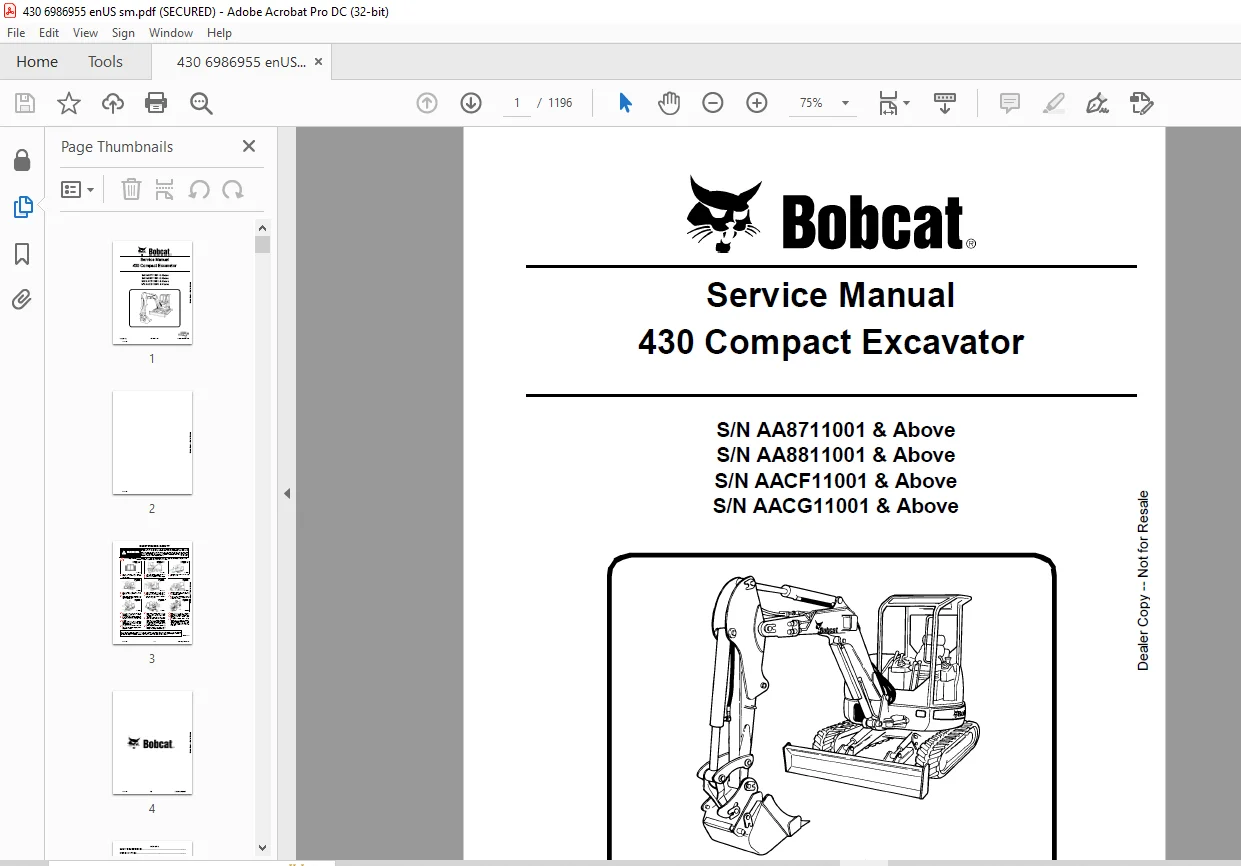
Bobcat 430 Compact Excavator Service Manual 6986955 (7-12) – PDF DOWNLOAD
S/N AA8711001 & Above
S/N AA8811001 & Above
S/N AACF11001 & Above
S/N AACG11001 & Above
Description
Bobcat 430 Compact Excavator Service Manual 6986955 (7-12) – PDF DOWNLOAD
FILE DETAILS:
Bobcat 430 Compact Excavator Service Manual 6986955 (7-12) – PDF DOWNLOAD
Language : English
Pages : 1196
Downloadable : Yes
File Type : PDF
Size:33.9 MB
DESCRIPTION:
Bobcat 430 Compact Excavator Service Manual 6986955 (7-12) – PDF DOWNLOAD
S/N AA8711001 & Above
S/N AA8811001 & Above
S/N AACF11001 & Above
S/N AACG11001 & Above
FOREWORD:
This manual is for the Bobcat loader mechanic. It provides necessary servicing and adjustment procedures for the Bobcat loader and its component parts and systems. Refer to the Operation & Maintenance Manual for operating instructions, Starting procedure, daily checks, etc.
The following publications provide information on the safe use and maintenance of the Bobcat machine and attachments:
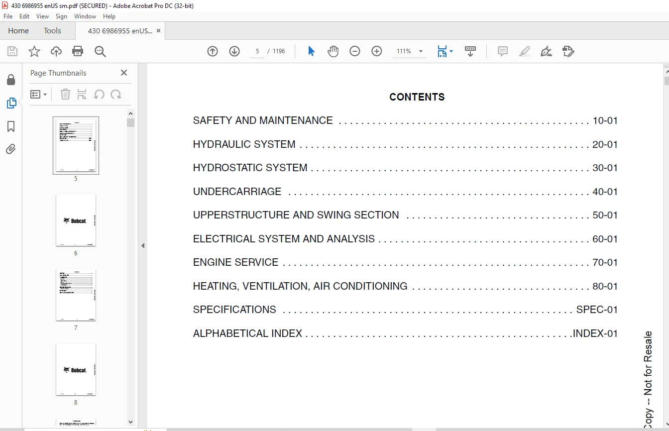
TABLE OF CONTENTS:
Bobcat 430 Compact Excavator Service Manual 6986955 (7-12) – PDF DOWNLOAD
MAINTENANCE SAFETY 3
CONTENTS 5
FOREWORD 7
FOREWORD 9
SAFETY INSTRUCTIONS 11
FIRE PREVENTION 13
Maintenance 13
Operation 13
Electrical 13
Hydraulic System 13
Fueling 13
Starting 13
Spark Arrester Exhaust System 13
Welding And Grinding 14
Fire Extinguishers 14
SERIAL NUMBER LOCATIONS 15
Excavator Serial Number 15
Engine Serial Number 15
DELIVERY REPORT 16
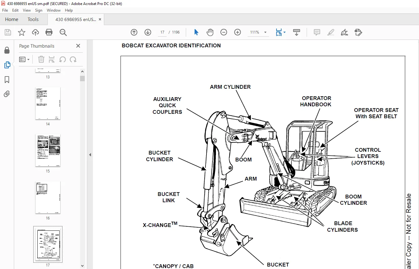
BOBCAT EXCAVATOR IDENTIFICATION 17
SAFETY AND MAINTENANCE 19
LIFTING AND BLOCKING THE EXCAVATOR 23
Procedure 23
UPPERSTRUCTURE SLEW LOCK 25
Operation 25
LIFTING THE EXCAVATOR 27
Procedure 27
OPERATOR CAB (ROPS / TOPS) 29
Description 29
Cab Door 29
Front Window 30
Front Wiper 32
Window Washer Reservoir 32
Right Side Window 33
Heating, Ventilation, And Air Conditioning Duct 34
TRANSPORTING THE EXCAVATOR ON A TRAILER 35
Loading And Unloading 35
Fastening 35
TAILGATE 37
Opening And Closing The Tailgate 37
Adjusting The Latch 37
RIGHT SIDE COVER 39
Opening And Closing The Right Side Cover 39
SERVICE SCHEDULE 41
Chart 41
AIR CLEANER 43
Daily Check 43
Replacing The Elements 43
HEATER AIR FILTER (WITH CAB OPTION ONLY) 45
Removal And Installation 45
ENGINE COOLING SYSTEM 47
Cleaning The Cooling System 47
Checking Coolant Level 47
Removing And Replacing Coolant 48
FUEL SYSTEM 51
Fuel Specifications 51
Biodiesel Blend Fuel 51
Filling The Fuel Tank 52
Removing Water 53
Replacing Element 53
Draining The Fuel Tank 54
Inline Fuel Filter 54
Removing Air From The Fuel System 54
ENGINE LUBRICATION SYSTEM 55
Checking And Adding Engine Oil 55
Engine Oil Chart 55
Removing And Replacing Oil And Filter 55
HYDRAULIC SYSTEM 57
Checking And Adding Fluid 57
Hydraulic Fluid Chart 58
Removing And Replacing The Hydraulic Fluid 59
Removing And Replacing The Hydraulic Filter 60
Removing And Replacing The Case Drain Filter 60
Removing And Replacing The Fan Filter 61
Diagnostic Couplers 61
LUBRICATNG THE EXCAVATOR 63
Lubrication Locations 63
TRAVEL MOTOR 67
Checking And Adding Oil 67
Removing And Replacing Oil 67
SPARK ARRESTER MUFFLER 69
Cleaning Procedure 69
ALTERNATOR BELT 71
Belt Tension 71
Belt Adjustment 71
SEAT BELT 73
Inspection And Maintenance 73
PIVOT PINS 75
Inspection And Maintenance 75
EXCAVATOR STORAGE AND RETURN TO SERVICE 77
Storage 77
Return To Service 77
STOPPING THE ENGINE AND LEAVING THE EXCAVATOR 79
Procedure 79
Emergency Exits 80
MOTION ALARM SYSTEM 81
Description 81
Inspecting 81
Adjusting Switch Position 81
HYDRAULIC SYSTEM 83
HYDRAULIC / HYDROSTATIC SCHEMATICS 91
HYDRAULIC SYSTEM INFORMATION 95
Glossary Of Hydraulic / Hydrostatic Symbols 95
Troubleshooting The Hydraulic Circuit 99
Troubleshooting The Cylinder Circuit 99
Troubleshooting The Swing (Upperstructure Slew) Circuit 100
Troubleshooting The Travel Circuit 101
CYLINDER (BOOM) 103
Testing 103
Removal And Installation 106
Parts Identification 109
Disassembly 110
Assembly 112
CYLINDER (ARM) 115
Testing 115
Removal And Installation 117
Parts Identification 119
Disassembly 120
Assembly 122
CYLINDER (BOOM SWING) 125
Testing 125
Removal And Installation 126
Parts Identification 128
Disassembly 129
Assembly 131
CYLINDER (BUCKET) 135
Testing 135
Removal And Installation 137
Parts Identification 139
Disassembly 140
Assembly 142
CYLINDER (BLADE) 147
Testing 147
Removal And Installation 148
Parts Identification 149
Disassembly 150
Assembly 152
CYLINDER (CLAMP) 155
Testing 155
Removal And Installation 156
Parts Identification 157
Disassembly 158
Assembly 161
CYLINDER (ANGLE BLADE) 167
Testing 167
Removal And Installation 168
Parts Identification 170
Disassembly 171
Assembly 173
CYLINDER (EXTENDIBLE ARM) 177
Removal And Installation 177
Parts Identification 179
Disassembly 180
Assembly 182
VALVES (MAIN RELIEF) 187
Testing And Adjusting The Main Relief Valves (S/N AACF11001 & Above And AA8711001 & Above) 187
System Pressures At Gauge Port Specifications 187
Testing And Adjusting The Main Relief Valves (S/N AACG11001 & Above And AA8811001 & Above) 190
System Pressures At Gauge Port Specifications 190
VALVES (PORT RELIEF) 193
Testing And Adjusting Port Relief Valve Pressure 193
VALVES (CROSSPORT RELIEF) 197
Testing And Adjusting The Crossport Relief Valves (S/N AACF11001 & Above And AA8711001 & Above) 197
Testing And Adjusting The Crossport Relief Valves (S/N AACG11001 & Above And AA8811001 & Above) 199
VALVE (PRESSURE REDUCING) 201
Description 201
VALVE (ANGLE BLADE) 203
Description 203
Testing And Adjusting Port Relief Valves 203
Testing And Adjusting Sequence Valve 205
Removal And Installation 207
Parts Identification 210
Disassembly 211
Assembly 224
HYDRAULIC CONTROL VALVE (S/N AACF11001 & ABOVE AND AA8711001 & ABOVE) 237
Description 237
Removal And Installation 237
Parts Identification 243
Disassembly 244
Right Travel Valve Section Disassembly And Assembly 246
Left Travel Valve Section Disassembly And Assembly 250
Blade Valve Section Disassembly And Assembly 254
Slew Valve Section Disassembly And Assembly 263
Auxiliary Valve Section Disassembly And Assembly 268
Bucket Valve Section Disassembly And Assembly 273
Arm Valve Section Disassembly And Assembly 278
Boom Valve Section Disassembly And Assembly 283
Boom Swing Valve Section Disassembly And Assembly 288
Inlet Section Disassembly And Assembly 293
Assembly 298
HYDRAULIC CONTROL VALVE (S/N AACG11001 & ABOVE AND AA8811001 & ABOVE) 305
Description 305
Removal And Installation 305
Parts Identification 308
Disassembly 309
Blade Valve Section Disassembly And Assembly 310
Slew Valve Section Disassembly And Assembly 319
Auxiliary Valve Section Disassembly And Assembly 324
Bucket Valve Section Disassembly And Assembly 329
Arm Valve Section Disassembly And Assembly 334
Boom Valve Section Disassembly And Assembly 339
Boom Swing Valve Section Disassembly And Assembly 344
Inlet Section Disassembly And Assembly 349
Assembly 354
HYDRAULIC PUMP 359
Description 359
Torque Adjustment 360
Testing The Piston Pump 361
Testing The Gear Pump 363
Testing Auxiliary Flow 365
Removal And Installation 366
Coupler Removal And Installation 367
Hydraulic Pump Start Up 368
Gear Pump Parts Identification 369
Piston Pump Parts Identification 370
Disassembly 371
Gear Pump Disassembly 373
Gear Pump Assembly 376
Piston Pump Disassembly 379
Piston Pump Assembly 386
Assembly 393
MANIFOLD ASSEMBLY / ACCUMULATOR (S/N AACG11001 & ABOVE AND AA8811001 & ABOVE) 395
Description 395
Testing Pilot Pressure 396
Removal And Installation 397
Parts Identification 399
Disassembly 400
Assembly 412
MANIFOLD ASSEMBLY / ACCUMULATOR (S/N AACF11001 & ABOVE AND AA8711001 & ABOVE) 425
Description 425
Testing Pilot Pressure 426
Removal And Installation 427
Parts Identification 429
Disassembly 430
Assembly 439
TRAVEL MOTOR (S/N AACG11001 & ABOVE AND AA8811001) 449
Description 449
Removal And Installation 449
Parts Identification 451
Disassembly 452
Assembly 466
TRAVEL MOTOR (S/N AACF11001 & ABOVE AND AA8711001 & ABOVE) 483
Description 483
Removal And Installation 483
Parts Identification 484
Disassembly 485
Assembly 495
SWIVEL JOINT 507
Removal And Installation 507
Parts Identification 509
Description 510
Disassembly 510
Assembly 513
SWING MOTOR 517
Description 517
Removal And Installation 517
Parts Identification 519
Disassembly 520
Assembly 525
SWING MOTOR (DRIVE CARRIER) 531
Description 531
Removal And Installation 531
Parts Identification 532
Disassembly 533
Assembly 535
CONTROL PATTERN SELECTOR VALVE 539
Description 539
Removal And Installation 539
Parts Identification 540
Disassembly 541
Assembly 543
RIGHT CONTROL LEVER (JOYSTICK) 545
Description 545
Testing 545
Handle Removal And Installation 546
Joystick Assembly Removal And Installation 550
Parts Identification 553
Disassembly 554
Assembly 559
LEFT CONTROL LEVER (JOYSTICK) 563
Description 563
Testing 563
Handle Removal And Installation 565
Joystick Assembly Removal And Installation 568
Parts Identification 570
Disassembly 571
Assembly 576
TRAVEL CONTROL VALVE (S/N AACG11001 & ABOVE AND AA8811001 & ABOVE) 581
Removal and Installation 581
Parts Identification 582
Disassembly And Assembly 583
TRAVEL CONTROL VALVE (S/N AACF11001 & ABOVE AND AA8711001 & ABOVE) 589
Removal and Installation 589
Parts Identification 590
Disassembly And Assembly 591
HOSES 595
Hose Guide Location 595
Left Control Lever (Joystick) (S/N AACF11001 & Above AND AA8711001 & Above) 596
Left Control Lever (Joystick) (S/N AACG11001 AND AA8811001 & Above) 597
Right Control Lever (Joystick) (S/N AACF11001 And Above AA8711001 & Above) 598
Right Control Lever (Joystick) (S/N AACG11001 & Above And AA8811001 & Above) 599
Travel Control Valve (S/N AACF11001 & Above And AA8711001 & Above) 600
Travel Control Valve (S/N AACG11001 & Above And AA8811001 & Above) 601
Manifold Assembly / Accumulator (S/N AACF11001 & Above And AA8711001 & Above) 602
Manifold Assembly / Accumulator (S/N AACG11001 & Above And AA8811001 & Above) 603
HYDRAULIC FILTER 605
Description 605
Housing Removal And Installation 605
CASE DRAIN FILTER 607
Removal And Installation 607
HYDRAULIC RESERVOIR 609
Description 609
Removal And Installation 609
OIL COOLER 611
Description 611
Removal And Installation 611
DIRECT TO TANK VALVE 615
Description 615
Removal And Installation 615
Parts Identification 616
Disassembly And Assembly 617
BUILD UP VALVE 619
COOLING FAN 621
Description 621
Testing 621
Removal And Installation 622
Parts Identification 624
Disassembly And Assembly 625
BOOM SWING LOCK VALVE 633
Description 633
Removal And Installation 633
Parts Identification 634
Disassembly 635
Assembly 638
HYDRAULIC X-CHANGE™ VALVE 643
Removal And Installation 643
Parts Identification 646
Disassembly 647
Assembly 655
SLEW LOCK VALVE 663
Description 663
Removal And Installation 663
Parts Identification 664
Disassembly And Assembly 665
HYDROSTATIC SYSTEM 669
HYDROSTATIC SYSTEM INFORMATION 671
Troubleshooting Chart 671
Relief / Replenishing Valve Function 672
Relief / Replenishing Valve Location 672
Relief / Replenishing Valve Removal And Installation 673
Charge Pressure Relief Valve Location 674
Charge Pressure Relief Valve Removal And Installation 674
TRAVEL PILOT PRESSURE 675
Description 675
Testing 675
HYDROSTATIC PUMP 677
Removal And Installation 677
Parts Identification (Front) (S/N AACG11001 & Above And AA8811001 & Above) 680
Disassembly 681
Inspection 696
Assembly 700
Hydrostatic Pump Start-Up 715
Mechanical Neutral Adjustment 715
DRIVE BELT SHIELD 719
Removal And Installation 719
DRIVE BELT 721
Adjustment 721
Removal And Installation 723
UNDERCARRIAGE 725
BLADE 727
Removal And Installation 727
ANGLE BLADE ASSEMBLY 729
Removal And Installation 729
ANGLE BLADE 731
Removal And Installation 731
ANGLE BLADE CUTTING EDGE 733
Removal And Installation 733
TRACK FRAME COMPONENTS 735
Description 735
Track Lug Height 735
Checking Tension 736
Adjusting Tension 738
Rubber Track Removal And Installation 739
Steel Track Removal And Installation 742
Idler (Front) Removal And Installation 745
Idler (Front) Parts Identification 747
Idler (Front) Disassembly 748
Idler (Front) Assembly 750
Coil Spring Assembly And Cylinder (S/N AACF11246 & Below, AACG11102 & Below, AA8711102 & Below And AA8811101 & Below) 753
Coil Spring Cylinder Parts Identification (S/N AACF11247 & Above, AACG11103 & Above, AA8711103 & Above And AA8811102 & Above) 754
Coil Spring Cylinder Disassembly And Assembly (S/ N AACF11247 & Above, AACG11103 & Above, AA8711103 & Above And AA8811102 & Above) 755
Roller Removal And Installation 757
Roller Parts Identification 758
Roller Disassembly 759
Roller Assembly 761
Track Damage Identification 763
Abrasion Of Embedded Metals 764
SWING CIRCLE GEAR 775
Swing Bearing Removal 775
Swing Bearing Installation 776
UPPERSTRUCTURE AND SWING SECTION 777
UPPERSTRUCTURE 781
Description 781
Removal 781
Installation 784
CANOPY 787
Removal And Installation 787
CAB 791
Removal And Installation 791
Door Removal And Installation 795
Front Window Removal And Installation 796
Right Side Rear Sliding Window Removal And Installation 799
Right Side Front Sliding Window Removal And Installation 799
Glass Removal 800
Right Side Front And Rear Sliding Window Weather Strip Removal And Installation 800
Right Side Front And Rear Sliding Window Wiper Strip Removal And Installation 800
Glass Installation 801
SEAT AND SEAT MOUNT 803
Seat Mount Removal And Installation 803
Seat Removal And Installation 803
RIGHT CONSOLE 805
Description 805
Console Cover Removal And Installation 805
Console Frame Removal And Installation 806
LEFT CONSOLE 809
Description 809
Joystick Console Cover (Bottom) Removal And Installation 809
Joystick Console Cover (Top) Removal And Installation 809
Compression Spring Removal And Installation 811
Compression Spring Disassembly And Assembly 812
Lever Removal And Installation 814
Joystick Console Frame Removal And Installation 815
Joystick Console Frame Disassembly And Assembly 819
Left Rear Console Cover Removal And Installation 821
Left Rear Console Frame Removal And Installation 822
BLADE CONTROL 823
Removal And Installation 823
Linkage Removal And Installation 824
Linkage Disassembly And Assembly 824
Control Cable Removal And Installation 826
UPPERSTRUCTURE SLEW LOCK 827
Removal And Installation 827
Disassembly And Assembly 828
FLOOR MAT AND FLOOR PLATES 831
Description 831
Removal And Installation 831
BOOM SWING PEDAL 833
Description 833
Pedal Removal And Installation 833
Pedal Disassembly And Assembly 834
Control Cable Removal And Installation 836
TRAVEL LEVERS / PEDALS 837
Description 837
Adjustment 837
Removal And Installation 840
Disassembly And Assembly 843
Control Linkage Assembly Removal And Installation 845
FUEL TANK 847
Removal And Installation 847
HORN 849
Removal And Installation 849
SWING FRAME 851
Description 851
Removal And Installation 851
Hose Routing 855
Bushing Removal 856
Bushing Installation 857
BOOM 859
Description 859
Removal And Installation 859
ARM 861
Description 861
Removal And Installation 861
Arm To Boom Bushing Removal And Installation 862
Arm To Bucket And Bucket Link Bushing Removal And Installation 863
BUCKET 865
Removal And Installation (Pin-On X-Change™) 865
Removal And Installation (Bolt-On X-Change™) 871
Removal And Installation (Pin-On Attachment) 877
Removal And Installation (Hydraulic X-Change™) 878
Bucket Teeth Removal And Installation 883
Bucket Side Cutting Edge Removal And Installation 884
CLAMP 885
Removal And Installation 885
TAILGATE 887
Removal And Installation 887
X-CHANGE™ 889
Removal And Installation 889
Parts Identification 891
Disassembly 892
Assembly 897
Check Proper Latch Engagement 903
X-CHANGE™ (HYDRAULIC) 907
Removal And Installation 907
Parts Identification 910
Disassembly 911
Assembly 916
RIGHT SIDE COVER 925
Removal And Installation 925
COUNTERWEIGHT 927
Removal And Installation 927
QUICK COUPLER (KLAC™ SYSTEM) 929
Troubleshooting 929
Daily Inspection 929
Removal And Installation 930
Parts Identification 932
Disassembly 933
Assembly 934
QUICK COUPLER (LEHNHOFF® SYSTEM) 937
Troubleshooting 937
Daily Inspection 937
Removal (MS03 And MS08) 938
Installation (MS03 And MS08) 939
Parts Identification (MS03) 940
Disassembly And Assembly (MS03) 941
Parts Identification (MS08) 942
Disassembly (MS08) 943
Assembly (MS08) 946
ELECTRICAL SYSTEM AND ANALYSIS 951
ELECTRICAL SCHEMATICS 953
ELECTRICAL SYSTEM INFORMATION 955
Troubleshooting Chart 955
Description 956
Fuse And Relay Location 956
BATTERY 957
Removing And Installing The Battery 957
Servicing 958
Using A Booster Battery (Jump Starting) 959
ALTERNATOR 961
Belt Adjustment 961
Belt Replacement 961
Charging System Inspection 962
Alternator Description 963
High Voltage Test 964
Rectifier Continuity (Diode) Test 964
Alternator Voltage Test 965
Low Voltage Test 965
Alternator Regulator Test 966
Parts Identification 967
Disassembly 967
Stator Continuity Test 967
Stator Ground Test 968
Rotor Continuity Test 968
Rotor Ground Test 969
Assembly 969
Removal And Installation 970
STARTER 971
Testing 971
Removal And Installation 971
Parts Identification 972
Disassembly 973
Inspection And Repair 978
Assembly 981
LIGHTS 987
Upperstructure Light Removal And Installation 987
Upperstructure Light Disassembly And Assembly 987
Boom Light Removal And Installation 988
Boom Light Bulb Replacement 988
MAGNETIC LOCKOUT SENSOR 989
Testing Left Console Magnetic Lockout Sensor 989
Console Switch Removal And Installation 990
FUEL LEVEL SENDER 991
Removal And Installation 991
Testing 991
DIAGNOSTICS SERVICE CODES 993
Description 993
DELUXE INSTRUMENT PANEL SETUP 995
Passwords 995
Password Entry (For Starting And Operating The Machine) 995
Changing The Owner or Operator Password 995
Password Lockout Feature 996
Job Clock 996
RPM 996
TWO-SPEED SWITCH 997
Removal And Installation 997
ENGINE SERVICE 999
ENGINE INFORMATION 1001
Description 1001
Specifications 1002
Torque Values 1008
Troubleshooting Chart 1009
Removal And Installation 1010
Compression Checking 1018
ENGINE SPEED CONTROL 1019
Removal And Installation 1019
Disassembly And Assembly 1020
Adjustment (S/N AA8711001 & Above And AA8811001 & Above) 1021
SPARK ARRESTER MUFFLER 1023
Removal And Installation 1023
AIR CLEANER 1025
Removal And Installation 1025
ENGINE COOLING SYSTEM 1027
Radiator Removal And Installation 1027
Testing The Thermostat 1032
Thermostat Housing Removal And Installation 1033
Water Pump Removal And Installation 1034
Water Pump Disassembly And Assembly 1034
LUBRICATION SYSTEM 1035
Oil Pan Removal And Installation 1035
Oil Pump Removal And Installation 1035
Oil Pump Inspection 1036
Engine Oil Pressure – Testing 1037
FUEL SYSTEM 1039
Fuel Camshaft Removal And Installation 1039
Fuel Camshaft Governor Disassembly And Assembly 1039
Fuel ShutOff Solenoid – Checking 1040
Fuel Shut-off Solenoid Removal And Installation 1041
Fuel Injection Pump Removal And Installation 1043
Injection Pump Timing 1046
Fuel Injector Removal And Installation 1048
Fuel Injector Nozzle Pressure – Checking 1051
Nozzle Spray Condition 1051
Valve Seat Tightness 1052
ENGINE FLYWHEEL (LATER MODELS) 1053
Removal And Installation 1053
Hydraulic Pump Coupler 1054
Flywheel Ring Gear 1054
CYLINDER HEAD 1055
Glow Plug Testing 1055
Glow Plug Removal And Installation 1056
Valve Clearance Adjustment 1057
Valve Timing – Checking 1057
Cylinder Head Removal And Installation 1058
Cylinder Head Disassembly And Assembly 1061
Cylinder Head Servicing 1062
Cylinder Head Top Clearance 1062
Valve Guide Checking 1063
Reconditioning The Valve And Valve Seat 1065
Valve Spring 1066
Valve Tappets 1067
Rocker Arm And Shaft – Checking 1067
CRANKSHAFT AND PISTONS 1069
Piston And Connecting Rod Removal And Installation 1069
Piston And Connecting Rod Servicing 1071
Connecting Rod Alignment 1073
Crankshaft And Bearings Removal And Installation 1074
Crankshaft And Bearings Servicing 1076
Cylinder Bore, Checking 1079
CRANKSHAFT AND TIMING GEARS 1081
Timing Gearcase Cover Removal And Installation 1081
Timing Gears Backlash – Checking 1083
Idler Gear And Shaft Removal And Installation 1084
Camshaft Servicing 1085
Idler Gear And Shaft Servicing 1086
ENGINE FLYWHEEL 1087
Hydraulic Pump Coupler Removal And Installation 1087
Flywheel Removal And Installation 1087
Flywheel Ring Gear 1087
HEATING, VENTILATION, AIR CONDITIONING 1089
HEATER SYSTEM 1091
Description 1091
Components 1091
REGULAR MAINTENANCE 1095
Filter Element Removal And Installation 1095
Engine Accessory Drive Belt 1095
Cleaning The Condenser 1096
Cleaning The A/C Evaporator Coil And Heater Coil 1097
TROUBLESHOOTING 1099
Blower Motor Does Not Operate 1099
Blower Motor Operators Normally, But Air Flow Is Insufficient 1099
Insufficient Cooling Although Air Flow And Compressor Operation Are Normal 1099
The Compressor Does Not Operate At All, Or Operates Improperly 1099
Gauge Pressure Related Troubleshooting 1100
Electrical System 1102
Engine Coolant Bypassing The Heater Valve 1112
Poor A/C Performance 1113
EVAPORATOR / HEATER UNIT 1115
Removal And Installation 1115
Disassembly And Assembly 1116
HEATER COIL 1117
Removal And Installation With A/C 1117
Removal And Installation Without A/C 1117
BLOWER FAN 1119
Removal And Installation 1119
Disassembly And Assembly 1120
Resistor Removal And Installation 1121
HEATER VALVE 1123
Removal And Installation 1123
AIR CONDITIONING SERVICE 1125
Safety Equipment 1125
Chart 1126
Reclamation Procedure 1127
Compressor Oil 1130
Compressor Oil Check 1131
Component Replacement And Refrigeration Leaks 1133
Temperature / Pressure Chart 1134
Charging Procedure With A Manifold Gauge Set 1135
COMPRESSOR 1139
Removal And Installation 1139
Compressor Clutch Disassembly And Assembly 1140
CONDENSER 1143
Removal And Installation 1143
RECEIVER / DRIER 1145
Removal And Installation 1145
PRESSURE RELIEF VALVE 1147
Removal And Installation 1147
PRESSURE SWITCH 1149
Removal And Installation 1149
THERMOSTAT 1151
Removal And Installation 1151
EXPANSION VALVE 1153
Removal And Installation 1153
EVAPORATOR 1155
Removal And Installation 1155
SPECIFICATIONS 1157
EXCAVATOR SPECIFICATIONS 1159
Excavator Dimensions With Standard Arm, Long Arm Option And Extendable Arm Kit 1159
Excavator Standard Arm Machine Dimensions 1160
Excavator Long Arm Machine Dimensions 1161
Excavator Extendable Arm Machine Dimensions 1162
Excavator With Optional Angle Blade Dimensions 1163
Performance – Conventional (S/N AACF11001 & Above And AA8711001 & Above) 1164
Performance – FastTrack (S/N AACG11001 & Above And AA8811001 & Above) 1164
Controls 1164
Engine 1165
Hydraulic System 1166
Hydraulic Cylinders 1167
Hydraulic Cycle Times 1167
Electrical 1167
Undercarriage 1168
Capacities 1168
Tracks 1168
Drive System- Conventional (S/N AACF11001 & Above, AA8711001 & Above) 1169
Drive System – FastTrack (S/N AACG11001 & Above, AA8811001 & Above) 1169
Slew System 1169
Ground Pressure – Conventional 1169
Ground Pressure – FastTrack 1169
TORQUE SPECIFICATIONS FOR BOLTS 1171
Torque For General SAE Bolts 1171
Torque For General Metric Bolts 1172
HYDRAULIC CONNECTION SPECIFICATIONS 1173
O-ring Face Seal Connection 1173
Straight Thread O-ring Fitting 1173
Tubelines And Hoses 1173
Flare Fitting 1174
O-ring Flare Fitting 1175
Port Seal Fitting 1177
HYDRAULIC FLUID SPECIFICATIONS 1179
Specifications 1179
FUEL, COOLANT AND LUBRICANTS 1181
Chart 1181
CONVERSIONS 1183
Decimal And Millimeter Equivalents Chart 1183
U S To Metric Conversion Chart 1183
ALPHABETICAL INDEX 1185
SERVICE MANUAL REVISION 1189
Revision No: 430 – 1 1189
Revision No: 430 – 2 1191
Revision No: 430 – 3 1193
Revision No: 430 – 4 1195
IMAGES PREVIEW OF THE MANUAL:
Contact us: [email protected]
https://vimeo.com/841419448?share=copy
PLEASE NOTE:
- This is the SAME manual used by the dealers to troubleshoot any faults in your vehicle. This can be yours in 2 minutes after the payment is made.
- Contact us at [email protected] should you have any queries before your purchase or that you need any other service / repair / parts operators manual.
S.M