Bobcat 435 Excavator Service Manual 6902331 (4-08) – PDF DOWNLOAD
$34.95
Bobcat 435 Excavator Service Manual 6902331 (4-08) – PDF DOWNLOAD
S/N 562611001 & Above
S/N 562811001 & Above
S/N 563111001 & Above
S/N 563211001 & Above
Description
Bobcat 435 Excavator Service Manual 6902331 (4-08) – PDF DOWNLOAD
FILE DETAILS:
Bobcat 435 Excavator Service Manual 6902331 (4-08) – PDF DOWNLOAD
Language : English
Pages :1537
Downloadable : Yes
File Type : PDF
Size:39.1 MB
DESCRIPTION:
Bobcat 435 Excavator Service Manual 6902331 (4-08) – PDF DOWNLOAD
S/N 562611001 & Above
S/N 562811001 & Above
S/N 563111001 & Above
S/N 563211001 & Above
FOREWORD:
This manual is for the Bobcat loader mechanic. It provides necessary servicing and adjustment procedures for the Bobcat loader and its component parts and systems. Refer to the Operation & Maintenance Manual for operating instructions, Starting procedure, daily checks, etc.
The following publications provide information on the safe use and maintenance of the Bobcat machine and attachments:
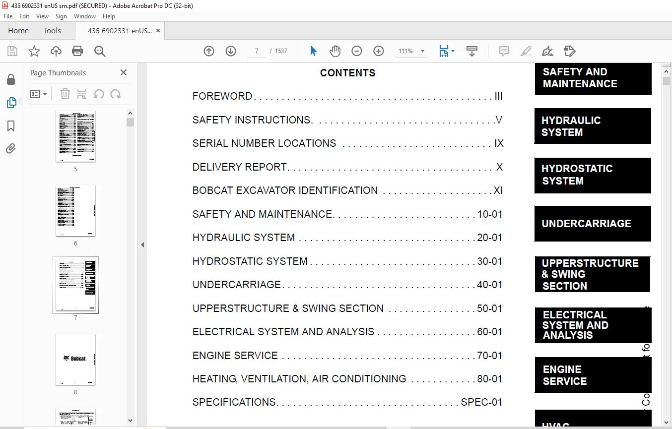
TABLE OF CONTENTS:
Bobcat 435 Excavator Service Manual 6902331 (4-08) – PDF DOWNLOAD
MAINTENANCE SAFETY 3
ALPHABETICAL INDEX 5
CONTENTS 7
FOREWORD 9
SAFETY INSTRUCTIONS 11
Fire Prevention 13
SERIAL NUMBER LOCATIONS 15
Excavator Serial Number 15
Engine Serial Number 15
DELIVERY REPORT 16
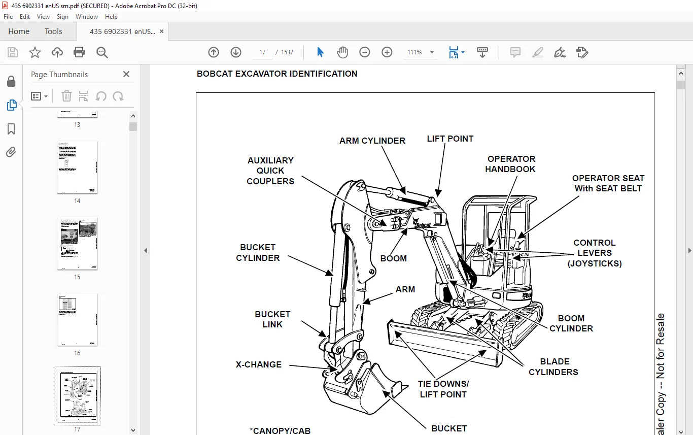
BOBCAT EXCAVATOR IDENTIFICATION 17
SAFETY AND MAINTENANCE 19
LIFTING AND BLOCKING THE EXCAVATOR 21
Procedure 21
UPPERSTRUCTURE SLEW LOCK 23
Operation 23
LIFTING THE EXCAVATOR 25
OPERATOR CAB (ROPS/TOPS) 27
Emergency Exit (Early Models) 27
Emergency Exit (Later Models) 28
Cab Door 29
Front Window 30
Right Side Windows (Early Models) 31
Right Side Windows (Later Models) 32
TRANSPORTING THE EXCAVATOR 35
Procedure 35
TAILGATE 37
Opening And Closing The Tailgate 37
Adjusting The Latch 37
RIGHT SIDE COVER 39
Opening And Closing The Right Side Cover 39
SERVICE SCHEDULE 41
Chart 41
AIR CLEANER 43
Daily Check 43
Replacing The Filters 43
HEATER AIR FILTER (WITH CAB OPTION ONLY) 45
Removal And Installation 45
COOLING SYSTEM 47
Cleaning The Cooling System 47
Checking Coolant Level 47
Replacing The Coolant 48
FUEL SYSTEM 51
Fuel Specifications 51
Filling The Fuel Tank 51
Removing Water From The Fuel Filter 52
Draining The Fuel Tank 52
Spin On Fuel Filter 53
Inline Fuel Filter 53
ENGINE LUBRICATION SYSTEM 55
Checking Engine Oil 55
Replacing Oil And Filter 55
HYDRAULIC SYSTEM 57
Checking And Adding Hydraulic Oil 57
Replacing The Hydraulic Oil 58
Replacing The Hydraulic Filter 59
Replacing The Case Drain Filter 59
Replacing The Fan Filter 60
Diagnostic Couplers 61
LUBRICATION OF THE HYDRAULIC EXCAVATOR 63
TRAVEL MOTOR 67
Checking Oil Level 67
Draining The Travel Motor 67
SPARK ARRESTOR MUFFLER 69
ENGINE ACCESSORY DRIVE BELT 71
Belt Tension 71
Belt Adjustment 71
HYDRAULIC SYSTEM 73
HYDRAULIC/HYDROSTATIC SCHEMATICS 81
HYDRAULIC SYSTEM INFORMATION 87
Glossary Of Hydraulic/Hydrostatic Symbols For Excavators 87
Troubleshooting The Hydraulic Circuit 90
Troubleshooting The Cylinder Circuit 91
Troubleshooting The Upperstructure Slew Circuit 92
BOOM CYLINDER 93
Testing 93
Removal And Installation 95
Parts Identification 98
Disassembly 99
Assembly 102
ARM CYLINDER 105
Testing 105
Removal and Installation 107
Parts Identification 109
Disassembly 110
Assembly 113
BOOM SWING CYLINDER 117
Testing 117
Removal And Installation 119
Parts Identification 121
Disassembly 122
Assembly 125
BUCKET CYLINDER 129
Testing 129
Removal And Installation 131
Parts Identification 132
Disassembly 133
Assembly 135
BLADE CYLINDER 139
Testing 139
Removal And Installation 140
Parts Identification 141
Disassembly 142
Assembly 144
CLAMP CYLINDER 147
Testing 147
Removal And Installation 148
Parts Identification 149
Disassembly 150
Assembly 153
ANGLE BLADE CYLINDER 159
Testing 159
Removal And Installation 160
Parts Identification 162
Disassembly 163
Assembly 165
MAIN RELIEF VALVES 169
PORT RELIEF VALVES 171
Port Relief Valve Pressure Setting 171
Parts Identification 171
Adjustment Procedure 172
CROSSPORT RELIEF VALVE 173
Testing And Adjusting The Crossport Relief Valve 173
Removal And Installation 175
Disassembly And Assembly 176
PRESSURE REDUCING VALVE 181
Description 181
ANGLE BLADE VALVE 183
Description 183
Testing And Adjusting Port Relief Valves 183
Testing And Adjusting Sequence Valve 185
Removal And Installation 187
Parts Identification 190
Disassembly 191
Assembly 204
HYDRAULIC CONTROL VALVE (S/N 562611001 & ABOVE, 562811001 & ABOVE AND 563211001 & ABOVE) 217
Removal And Installation 217
Parts Identification 220
Disassembly 221
Slew Valve Section Disassembly And Assembly 223
Blade Valve Section Disassembly And Assembly 229
Bucket Valve Section Disassembly And Assembly 241
Arm Valve Section Disassembly And Assembly 247
Boom Valve Section Disassembly And Assembly 253
Boom Swing Valve Section Disassembly And Assembly 259
Auxiliary Valve Section Disassembly And Assembly 265
Inlet Section Disassembly And Assembly 273
Assembly 278
HYDRAULIC CONTROL VALVE (S/N 563111001 & ABOVE) 283
Removal And Installation 283
Parts Identification 286
Disassembly 287
Right Travel Valve Section Disassembly And Assembly 289
Left Travel Valve Section Disassembly And Assembly 292
Slew Valve Section Disassembly And Assembly 295
Blade Valve Section Disassembly And Assembly 301
Bucket Valve Section Disassembly And Assembly 312
Arm Valve Section Disassembly And Assembly 318
Boom Valve Section Disassembly And Assembly 324
Boom Swing Valve Section Disassembly And Assembly 330
Auxiliary Valve Section Disassembly And Assembly 336
Inlet Section Disassembly And Assembly 344
Assembly 349
HYDRAULIC PUMP (S/N 562611001 & ABOVE AND 562811001 & ABOVE) 355
Hydraulic Pump Work Sheet 355
Pump Testing 358
Test Fitting Installation 358
Torque Limiter Adjustment 367
Removal And Installation 371
Coupler Removal And Installation 373
Torque Limiter Valve Parts Identification 374
Torque Limiter Valve Removal 375
Torque Limiter Valve Disassembly 375
Torque Limiter Valve Assembly 380
Initial Torque Limiter Valve Setting 383
Torque Limiter Valve Installation 385
Pump Control Parts Identification 386
Pump Control Removal And Installation 387
Pump Control Disassembly And Assembly 387
Parts Identification 393
Disassembly 394
Assembly 403
HYDRAULIC PUMP (S/N 563111001 & Above AND 563211001 & above) 413
Piston Pump Work Sheet 413
Piston Pump Testing 416
Test Fitting Installation 416
Torque Limiter Adjustment 423
Description 426
Gear Pump Testing 426
Removal And Installation 428
Coupler Removal And Installation 430
Hydraulic Pump Start Up 431
Torque Limiter Valve Parts Identification 432
Torque Limiter Valve Removal 433
Torque Limiter Valve Disassembly 434
Torque Limiter Valve Assembly 438
Initial Torque Limiter Valve Setting 441
Torque Limiter Valve Installation 443
Pump Control Parts Identification 444
Pump Control Removal And Installation 445
Pump Control Disassembly And Assembly 445
Parts Identification 451
Gear Pump Removal And Installation 452
Gear Pump Disassembly And Assembly 453
Piston Pump Parts Identification 458
Piston Pump Disassembly 459
Piston Pump Assembly 468
HYDRAULIC PUMP (S/N 563112526 & ABOVE AND 563212618 & ABOVE) 479
Hydraulic Pump Work Sheet 479
Piston Pump Testing 482
Test Fitting Installation 482
Back-up Relief Valve Adjustment 487
Torque Limiter Adjustment 491
Torque Limiter Adjustment 492
Description 494
Gear Pump Testing 494
Removal And Installation 496
Coupler Removal And Installation 498
Torque Limiter Valve Parts Identification 499
Torque Limiter Valve Removal 500
Torque Limiter Valve Disassembly 501
Torque Limiter Valve Assembly 505
Initial Torque Limiter Valve Setting 508
Torque Limiter Valve Installation 510
Pump Control Parts Identification 511
Pump Control Removal And Installation 512
Pump Control Disassembly And Assembly 512
Parts Identification 518
Gear Pump Removal And Installation 519
Gear Pump Disassembly And Assembly 520
HYDRAULIC PUMP (S/N 563112526 & ABOVE AND 563212618 & ABOVE) (CONT’D) 525
Piston Pump Parts Identification 525
HYDRAULIC PUMP (S/N 563112526 & ABOVE AND 563212618 & ABOVE) (CONT’D) 526
Piston Pump Disassembly 526
Piston Pump Assembly 535
MANIFOLD ASSEMBLY/ACCUMULATOR (S/N 562611001 & ABOVE, 562811001 & ABOVE, AND 563211001 – 563213999) 547
Description 547
Testing Pilot Pressure 548
Removal And Installation 549
Parts Identification 551
Disassembly 552
Assembly 565
MANIFOLD ASSEMBLY/ACCUMULATOR (S/N 563214000 & ABOVE) 577
Description 577
Testing Pilot Pressure 578
Removal And Installation 579
Parts Identification 581
Disassembly 582
Assembly 595
MANIFOLD ASSEMBLY/ACCUMULATOR (S/N 563111001 – 563113999) 607
Description 607
Testing Pilot Pressure 608
Removal And Installation 609
Parts Identification 611
Disassembly 612
Assembly 621
MANIFOLD ASSEMBLY/ACCUMULATOR (S/N 563114000 & ABOVE) 631
Description 631
Testing Pilot Pressure 632
Removal And Installation 633
Parts Identification 636
Disassembly 637
Assembly 646
TRAVEL MOTOR (S/N 562611001 & ABOVE, 562811001 & ABOVE, AND 563211001 & ABOVE) 655
Removal And Installation 655
Parts Identification 657
Disassembly 658
Assembly 672
TRAVEL MOTOR (S/N 563111001 & ABOVE) (EARLY MODELS) 689
Removal And Installation 689
Parts Identification 691
Disassembly 692
Assembly 707
TRAVEL MOTOR (S/N 563111001 & ABOVE) (LATER MODELS) 723
Removal And Installation 723
Parts Identification 724
Disassembly 725
Assembly 735
SWIVEL JOINT 747
Removal And Installation 747
Parts Identification 749
Description 750
Disassembly 750
Assembly 753
SWING MOTOR 757
Removal And Installation 757
Parts Identification 761
Parts Identification (Cont’d) 762
Disassembly 763
Inspection 768
Assembly 769
SWING MOTOR DRIVE CARRIER 775
Removal And Installation 775
Parts Identification 776
Checking The Drive Carrier Shaft End Play 777
Disassembly 778
Inspection 780
Assembly 781
CONTROL PATTERN SELECTOR VALVE 785
Removal And Installation 785
Parts Identification 786
Disassembly 787
Assembly 789
RIGHT CONTROL LEVER (JOYSTICK) 791
Testing 791
Handle Removal And Installation 792
Joystick Assembly Removal And Installation 796
Parts Identification 799
Disassembly 800
Assembly 805
LEFT CONTROL LEVER (JOYSTICK) 809
Testing 809
Handle Removal And Installation 811
Joystick Assembly Removal And Installation 814
Parts Identification 816
Disassembly 817
Assembly 822
TRAVEL CONTROL VALVE (S/N 562611001 & ABOVE, 562811001 & ABOVE AND 563211001 & ABOVE) 827
Removal and Installation 827
Parts Identification 828
Disassembly And Assembly 829
TRAVEL CONTROL VALVE (S/N 563111001 & ABOVE) 835
Removal and Installation 835
Parts Identification 836
Disassembly And Assembly 837
HOSES 841
Hose Guide Location 841
Left Control Lever (Joystick) (S/N 563114000-563114006 AND 563115000 & Above) 842
Left Control Lever (Joystick) (S/N 563214000 – 563214007 AND 563215000 & Above) 843
Right Control Lever (Joystick) (S/N 563114000 – 563114006 AND 563115000 & Above) 844
Right Control Lever (Joystick) (S/N 563214000 – 563214007 AND 563215000 & Above) 845
Travel Control Valve (S/N 563114000-563114006 AND 563115000 & Above) 846
Travel Control Valve (S/N 563214000 – 563214007 AND 563215000 & Above) 847
Manifold Assembly / Accumulator (S/N 563114000 – 563114006 AND 563115000 & Above) 848
Manifold Assembly / Accumulator (S/N 563214000 – 563214007 AND 563215000 & Above) 849
HYDRAULIC FILTER MOUNT 851
Removal And Installation 851
HYDRAULIC RESERVOIR 853
Removal And Installation 853
OIL COOLER 855
Removal And Installation 855
DIRECT TO TANK VALVE (IF EQUIPPED) 859
Removal And Installation 859
Parts Identification 860
Disassembly And Assembly 861
DUAL SEQUENCE VALVE (S/N 562611001 & ABOVE, 562811001 & ABOVE, 563111001 – 563113999 563211001 – 563213999) 863
Removal And Installation 863
Parts Identification 866
Disassembly And Assembly 867
DUAL SEQUENCE VALVE (S/N 563214000 & Above) 871
Removal And Installation 871
Parts Identification 873
Disassembly And Assembly 874
DUAL SEQUENCE VALVE (S/N 563114000 & Above) 877
Removal And Installation 877
Parts Identification 879
Disassembly And Assembly 880
BUILD UP VALVE 883
Removal And Installation 883
Parts Identification 884
Disassembly And Assembly 885
COOLING FAN 887
Description 887
Testing 887
Removal And Installation 888
Parts Identification 890
Disassembly And Assembly 891
REMOVING AIR FROM HYDRAULIC SYSTEM 899
Procedure 899
BOOM SWING LOCK VALVE 903
Description 903
Removal And Installation 903
Parts Identification 905
Disassembly 906
Assembly 909
HYDRAULIC X-CHANGE VALVE 913
Removal And Installation 913
Parts Identification 916
Disassembly 917
Assembly 925
HYDROSTATIC SYSTEM 933
HYDROSTATIC SYSTEM INFORMATION 935
Troubleshooting Chart 935
Relief/Replenishing Valve Function 936
Relief/Replenishing Valve Location 937
Relief/Replenishing Valve Removal And Installation 937
Charge Pressure Relief Valve Removal And Installation 938
Charge Pressure Relief Valve Disassembly And Assembly 938
TRAVEL PILOT PRESSURE 939
Description 939
Testing 939
HYDROSTATIC PUMP 941
Removal And Installation 941
Fan/Charge Pump Parts Identification 944
Fan/Charge Pump Disassembly And Assembly 945
Parts Identification (Front) (S/N 562611001 & Above, 562811001 & Above And 563211001 & Above) 950
Parts Identification (Rear) (S/N 562611001 & Above And 562811001 & Above) 951
Parts Identification (Rear) (S/N 563211001 & Above) 952
Disassembly 953
Inspection 964
Assembly 966
Hydrostatic Pump Start-Up 978
FAN/CHARGE PUMP 979
Description 979
Testing 979
DRIVE BELT SHIELD 981
Removal And Installation 981
DRIVE BELT 983
Adjustment 983
Removal And Installation 985
UNDERCARRIAGE 987
BLADE 989
Removal And Installation 989
ANGLE BLADE ASSEMBLY 991
Removal And Installation 991
ANGLE BLADE 993
Removal And Installation 993
ANGLE BLADE CUTTING EDGE 995
Removal And Installation 995
TRACKS 997
Track Lug Height 997
Rubber Track Clearance 998
Steel Track Clearance 999
Adjustment 999
Rubber Track Removal And Installation 1000
Steel Track Removal And Installation 1003
TRACK FRAME 1009
Disassembly And Assembly 1009
Recoil Spring Cylinder Disassembly And Assembly 1012
TRACK DAMAGE IDENTIFICATION 1013
Cutting Of Steel Cords 1013
Abrasion Of Embedded Metals 1014
Separation Of Embedded Metals 1015
Separation Of Embedded Metals Due To Corrosion 1016
Cuts On The Lug Side Rubber 1017
Cracks On The Lug Side Rubber Due To Fatigue 1018
Lug Abrasion 1019
Cracks And Cuts On The Lug Side Rubber 1020
Abrasion Of The Track Roller Side 1021
Cuts On The Edges Of Track Roller Side 1022
TRACK IDLER 1025
Parts Identification 1025
Disassembly 1026
Assembly 1028
UPPER TRACK ROLLER 1031
Parts Identification 1031
Disassembly 1032
Assembly 1033
LOWER TRACK ROLLER 1037
Parts Identification 1037
Disassembly 1038
Assembly 1039
SWING CIRCLE GEAR 1043
Swing Bearing Removal 1043
Swing Bearing Installation 1044
UPPERSTRUCTURE & SWING SECTION 1045
UPPERSTRUCTURE 1049
Removal 1049
Installation 1052
ROPS CANOPY 1055
Removal And Installation 1055
CAB 1059
Removal And Installation 1059
Door Removal And Installation 1064
Front Window Removal And Installation 1065
Right Side Rear Sliding Window Removal And Installation 1068
Right Side Front Sliding Window Removal And Installation 1068
Right Side Front And Rear Sliding Window Weather Strip Removal And Installation 1069
Right Side Front And Rear Sliding Window Wiper Strip Removal And Installation 1069
Glass Removal 1070
Glass Installation 1071
Glass Installation (Cont’d) 1072
Glass Installation (Cont’d) 1073
SEAT AND SEAT MOUNT 1075
Removal And Installation 1075
RIGHT CONSOLE 1077
Console Cover Removal And Installation 1077
Console Base Removal And Installation 1078
Console Base Removal And Installation (Cont’d) 1079
LEFT CONSOLE 1081
Lower Console Cover Removal And Installation 1081
Upper Console Cover Removal And Installation 1083
Compression Spring Removal And Installation 1084
Compression Spring Disassembly And Assembly 1085
Lock Lever Removal And Installation 1087
Console Removal And Installation 1088
Disassembly And Assembly 1092
Console Switch Removal And Installation 1095
Console Base Removal And Installation 1096
ENGINE SPEED CONTROL 1097
Removal And Installation 1097
Disassembly And Assembly 1098
Adjustment (Later Models) 1099
BLADE CONTROL 1101
Lever Removal And Installation 1101
Linkage Removal And Installation 1102
Linkage Disassembly And Assembly 1103
Control Cable Removal And Installation 1105
RIGHT PEDAL AND LINKAGE 1107
Pedal Removal And Installation 1107
Pedal Disassembly And Assembly 1108
Control Cable Removal And Installation 1110
TRAVEL CONTROLS 1111
Removal And Installation 1111
Disassembly And Assembly 1114
Adjustment 1116
CONTROL LINKAGE ASSEMBLY 1119
Removal And Installation 1119
FLOOR MAT AND FLOOR PLATES 1121
Removal And Installation 1121
FUEL TANK 1123
Removal And Installation 1123
HORN 1125
Removal And Installation (Earlier Models) 1125
Removal And Installation (Later Models) 1125
SWING FRAME 1127
Boom Swing Bracket Removal And Installation 1127
Boom Swing Bracket Hose Installation 1131
Bushing Removal 1132
Bushing Installation 1133
BOOM 1135
Removal And Installation 1135
ARM 1137
Removal And Installation 1137
Arm To Boom Bushing Removal And Installation 1138
Arm To Bucket And Bucket Link Bushing Removal & Installation 1139
BUCKET 1141
Bucket Teeth Removal And Installation 1141
Bucket Side Cutting Edge Removal And Installation 1142
TAILGATE 1143
Removal And Installation 1143
X-CHANGE 1145
Removal And Installation 1145
Parts Identification 1147
Disassembly 1148
Assembly 1153
Check Proper Latch Engagement 1159
X-CHANGE (PIN ON) 1163
Removal And Installation 1163
Parts Identification 1165
Disassembly And Assembly 1166
RIGHT SIDE COVER 1167
Removal And Installation 1167
X-CHANGE (HYDRAULIC) 1169
Removal And Installation 1169
Parts Identification 1172
Disassembly 1173
Assembly 1178
COUNTERWEIGHT 1187
Removal And Installation 1187
ELECTRICAL SYSTEM AND ANALYSIS 1189
ELECTRICAL SCHEMATICS 1191
ELECTRICAL SYSTEM INFORMATION 1194
Troubleshooting Chart 1194
Description 1195
Fuse And Relay Location 1195
BATTERY 1196
Servicing 1196
Removing And Installing The Battery 1197
Using A Booster Battery (Jump Starting) 1198
ALTERNATOR 1200
Engine Accessory Drive Belt 1200
Removal And Installation 1200
Alternator Identification 1201
Charging System Check 1202
Alternator Voltage Test 1203
Low Voltage Test 1203
High Voltage Test 1204
Rectifier Continuity (Diode) Test 1204
Alternator Regulator Test 1205
Parts Identification 1206
Disassembly 1206
Stator Continuity Test 1206
Stator Ground Test 1207
Rotor Continuity Test 1207
Rotor Ground Test 1208
Assembly 1208
STARTER 1210
Removal And Installation 1210
Parts Identification 1211
Disassembly 1212
Inspection And Repair 1217
Assembly 1220
LIGHTS 1226
Removal And Installation 1226
Boom Light Removal and Installation (Earlier Models) 1227
Boom Light Removal and Installation (Later Models) 1228
Boom Light Bulb Replacement (Later Models) 1228
TWO SPEED SWITCH 1230
Removal And Installation 1230
FUEL LEVEL SENDER 1232
Removal And Installation 1232
Testing 1233
DIAGNOSTICS SERVICE CODE 1234
Number Codes List 1234
DELUXE INSTRUMENT PANEL SETUP 1236
Passwords 1236
Password Entry (For Starting and Operating the Machine) 1236
Changing The Owner or Operator Password 1236
Password Lockout Feature 1237
Job Clock 1237
RPM 1237
ENGINE SERVICE 1238
TROUBLESHOOTING 1242
Chart 1242
MUFFLER 1244
Removal And Installation 1244
AIR CLEANER 1246
Removal And Installation 1246
RADIATOR 1248
Removal And Installation 1248
ENGINE COMPONENTS & TESTING (S/N 562611001 & ABOVE) 1254
Engine Compression Checking 1254
Glow Plug Removal And Installation 1255
Checking The Glow Plug 1258
Fuel Shut-off Solenoid Removal And Installation 1259
Fuel Injection Pump Check 1261
Fuel Injection Pump Removal And Installation 1262
Fuel Injection Pump Timing 1266
Fuel Injector Nozzles Removal And Installation 1268
Fuel Injector Nozzle Check 1272
Valve Clearance Adjustment 1273
ENGINE COMPONENTS & TESTING (S/N 562811001 & ABOVE, 563111001 & ABOVE AND 563211001 & ABOVE) 1274
Engine Compression Checking 1274
Glow Plug Removal And Installation 1275
Checking The Glow Plug 1278
Fuel Shut-off Solenoid Removal And Installation 1279
Fuel Injection Pump Check 1281
Fuel Injection Pump Removal And Installation 1282
Fuel Injection Pump Timing 1286
Fuel Injector Nozzles Removal And Installation 1288
Fuel Injector Nozzle Check 1292
Valve Clearance Adjustment 1293
ENGINE 1294
Removal And Installation 1294
ENGINE FLYWHEEL (EARLY MODELS) 1302
Removal And Installation 1302
Hydraulic Pump Coupler 1303
Flywheel Ring Gear 1303
ENGINE FLYWHEEL (LATER MODELS) 1304
Removal And Installation 1304
Hydraulic Pump Coupler 1305
Flywheel Ring Gear 1305
RECONDITIONING THE ENGINE (S/N 562611001 AND ABOVE) 1306
Cylinder Head Removal And Installation 1306
Cylinder Head Disassembly And Assembly 1308
Cylinder Head Servicing 1309
Cylinder Head Top Clearance 1309
Valve Guide Checking 1310
Reconditioning The Valve And Valve Seat 1312
Valve Spring 1313
Rocker Arm And Shaft Checking 1314
Timing Gearcase Cover Removal And Installation 1315
Idler Gear And Camshaft Removal And Installation 1317
Camshaft Servicing 1318
Idler Gear And Shaft Servicing 1319
Timing Gears Checking Backlash 1320
Fuel Camshaft Removal And Installation 1321
Fuel Camshaft Governor 1321
Crankshaft Gear Removal And Installation 1322
Oil Pump Removal And Installation 1322
Oil Pump Service 1323
Checking Engine Oil Pressure 1324
Relief Valve 1324
Piston And Connecting Rod Removal And Installation 1325
Piston And Connecting Rod Servicing 1327
Connecting Rod Alignment 1329
Crankshaft And Bearings Removal And Installation 1330
Crankshaft And Bearings Servicing 1332
Cylinder Bore Checking 1335
Water Pump Removal And Installation 1336
Water Pump Disassembly And Assembly 1336
RECONDITIONING THE ENGINE (S/N 562811001 & ABOVE, 563111001 & ABOVE AND 563211001 & ABOVE) 1338
Cylinder Head Removal And Installation 1338
Cylinder Head Disassembly And Assembly 1341
Cylinder Head Servicing 1342
Cylinder Head Top Clearance 1342
Valve Guide Checking 1343
Reconditioning The Valve And Valve Seat 1345
Valve Spring 1346
Rocker Arm And Shaft Checking 1347
Timing Gearcase Cover Removal And Installation 1347
Idler Gear And Camshaft Removal And Installation 1350
Camshaft Servicing 1351
Idler Gear And Shaft Servicing 1352
Timing Gears Checking Backlash 1353
Fuel Camshaft Removal And Installation 1353
Fuel Camshaft Governor 1354
Crankshaft Gear Removal And Installation 1354
Oil Pump Removal And Installation 1355
Oil Pump Service 1355
Checking Engine Oil Pressure 1356
Valve Tappets 1357
Piston And Connecting Rod Removal And Installation 1358
Piston And Connecting Rod Servicing 1360
Connecting Rod Alignment 1362
Crankshaft And Bearings Removal And Installation 1363
Crankshaft And Bearings Servicing 1366
Cylinder Bore Checking 1370
Water Pump Removal And Installation 1370
Water Pump Disassembly And Assembly 1371
HEATING, VENTILATION, AIR CONDITIONING 1372
HEATER COIL (EARLY MODELS) 1376
Removal And Installation 1376
HEATER COIL (LATER MODELS) 1378
Removal And Installation With A/C 1378
Removal And Installation Without A/C 1378
BLOWER FAN (EARLY MODELS) 1380
Removal And Installation 1380
Disassembly And Assembly 1381
BLOWER FAN (LATER MODELS) 1384
Removal And Installation 1384
Disassembly And Assembly 1385
Resistor Removal And Installation 1386
HEATER VALVE 1388
Removal And Installation 1388
AIR CONDITIONING SYSTEM FLOW 1391
Principals 1391
Chart 1392
COMPONENTS 1394
Identification 1394
SAFETY 1398
Safety Equipment 1398
REGULAR MAINTENANCE 1400
Heater Air Filter 1400
Engine Accessory Drive Belt 1400
Cleaning The Condenser 1400
BASIC TROUBLESHOOTING (EARLY MODELS) 1402
Poor A/C Performance 1402
Cleaning The A/C Evaporator Coil & Heater Coil 1403
Engine Accessory Drive Belt 1405
Checking The Electrical System 1406
Engine Coolant By-Passing The Heater Valve 1416
BASIC TROUBLESHOOTING (LATER MODELS) 1418
Poor A/C Performance 1418
Cleaning The A/C Evaporator Coil & Heater Coil 1419
Engine Accessory Drive Belt 1420
Checking The Electrical System 1421
Engine Coolant By-Passing The Heater Valve 1431
GENERAL AIR CONDITIONING SERVICE GUIDELINES 1432
Compressor Oil 1432
Compressor Oil Check 1433
Component Replacement And Refrigeration Leaks 1434
SYSTEM TROUBLESHOOTING CHART 1436
Blower Motor Does Not Operate 1436
Gauge Pressure Related Troubleshooting 1437
TEMPERATURE/PRESSURE 1440
Chart 1440
AIR CONDITIONING SERVICE 1442
Chart 1442
SYSTEM CHARGING AND RECLAMATION 1444
Reclamation Procedure 1444
Charging Procedure With A Manifold Gauge Set 1447
COMPRESSOR 1450
Removal And Installation 1450
Compressor Clutch Disassembly And Assembly 1451
CONDENSER 1454
Removal And Installation 1454
RECEIVER/DRIER 1456
Removal And Installation 1456
PRESSURE RELIEF VALVE 1458
Removal And Installation 1458
PRESSURE SWITCH 1460
Removal And Installation 1460
EVAPORATOR/HEATER UNIT (EARLY MODELS) 1462
Removal And Installation 1462
Disassembly And Assembly 1463
EVAPORATOR/HEATER UNIT (later MODELS) 1464
Removal And Installation 1464
Disassembly And Assembly 1465
THERMOSTAT (EARLY MODELS) 1466
Removal And Installation 1466
THERMOSTAT (LATER MODELS) 1468
Removal And Installation 1468
EXPANSION VALVE (EARLY MODELS) 1470
Removal And Installation 1470
EXPANSION VALVE (LATER MODELS) 1472
Removal And Installation 1472
EVAPORATOR (EARLY MODELS) 1474
Removal And Installation 1474
EVAPORATOR (LATER MODELS) 1476
Removal And Installation 1476
SPECIFICATIONS 1478
SPECIFICATIONS 1480
Excavator Machine Dimensions 1480
Performance (S/N 562611001 & Above, 562811001 & Above And 563211001 & Above) 1482
Performance (S/N 563111001 & Above) 1482
Controls 1482
Engine 1483
Hydraulic System 1484
Hydraulic Cylinders 1485
Hydraulic Cycle Times 1485
Drive System (S/N 562611001 & Above, 562811001 & Above And 563211001 & Above) 1485
Drive System (S/N 563111001 & Above) 1485
Undercarriage 1486
Track (S/N 562611001 & Above And 562811001 & Above) 1486
Track (S/N 563111001 & Above And 563211001 & Above) 1486
Electrical 1486
ENGINE SPECIFICATIONS (S/N 562611001 & ABOVE) 1488
Fuel Injection Nozzles 1488
Fuel Injection Pump 1488
Cylinder Head 1488
Valves 1488
Valve Springs 1489
Valve Timing 1489
Rocker Arms 1489
Camshaft 1489
Tappet 1489
Cylinders 1490
Piston Rings 1490
Pistons 1490
Connecting Rods 1490
Oil Pump 1490
Crankshaft 1491
Timing Gear 1491
Thermostat 1491
Engine Bolt Torque 1492
Crankshaft Re-Grind Data 1493
ENGINE SPECIFICATIONS (S/N 562811001 & ABOVE, 563111001 & ABOVE AND 563211001 & ABOVE) 1494
Fuel Injection Nozzles 1494
Fuel Injection Pump 1494
Cylinder Head 1494
Valves 1494
Valve Springs 1495
Valve Timing 1495
Rocker Arms 1495
Camshaft 1495
Tappet 1495
Cylinders 1496
Piston Rings 1496
Pistons 1496
Connecting Rods 1496
Oil Pump 1496
Crankshaft 1497
Timing Gear 1497
Thermostat 1498
Engine Bolt Torque 1498
Crankshaft Re-Grind Data 1499
TORQUE SPECIFICATIONS 1500
Torque for General SAE Bolts 1500
Torque For General Metric Bolts 1501
HYDRAULIC CONNECTION SPECIFICATIONS 1502
O-Ring Face Seal Connection 1502
Straight Thread O-ring Fitting 1502
Tubelines And Hoses 1502
Flare Fitting 1503
O-Ring Flare Fitting 1504
Port Seal Fitting 1506
HYDRAULIC FLUID SPECIFICATIONS 1508
Specifications 1508
FUEL, COOLANT AND LUBRICANTS 1510
Chart 1510
CONVERSIONS 1512
Decimal And Millimeter Equivalents 1512
U S To Metric Conversion Chart 1512
SMR 1514
435-1 1514
435-2 1516
435-3 1518
435-4 1520
435-5 1522
435-6 1524
435-7 1526
435-8 1528
435-9 1530
435-10 1532
435-11 1534
435-12 1536
IMAGES PREVIEW OF THE MANUAL:
Questions? Email us: [email protected]
https://vimeo.com/841418744?share=copy
PLEASE NOTE:
- This is the SAME exact manual used by your dealers to fix your vehicle.
- The same can be yours in the next 2-3 mins as you will be directed to the download page immediately after paying for the manual.
- Any queries / doubts regarding your purchase, please feel free to contact [email protected]
S.M


