Bobcat 442 Compact Excavator Service Manual 6987204 (5-10) – PDF DOWNLOAD
$33.95
Bobcat 442 Compact Excavator Service Manual 6987204 (5-10) – PDF DOWNLOAD
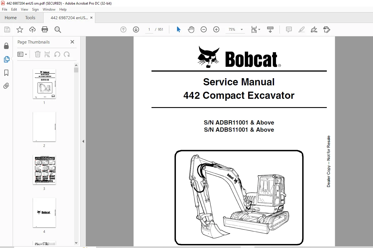
S/N ADBR11001 & Above
S/N ADBS11001 & Above
Description
Bobcat 442 Compact Excavator Service Manual 6987204 (5-10) – PDF DOWNLOAD
FILE DETAILS:
Bobcat 442 Compact Excavator Service Manual 6987204 (5-10) – PDF DOWNLOAD
Language : English
Pages : 951
Downloadable : Yes
File Type : PDF
Size: 28.1 MB
DESCRIPTION:
Bobcat 442 Compact Excavator Service Manual 6987204 (5-10) – PDF DOWNLOAD
S/N ADBR11001 & Above
S/N ADBS11001 & Above
FOREWORD:
This manual is for the Bobcat loader mechanic. It provides necessary servicing and adjustment procedures for the Bobcat loader and its component parts and systems. Refer to the Operation & Maintenance Manual for operating instructions, Starting procedure, daily checks, etc.
The following publications provide information on the safe use and maintenance of the Bobcat machine and attachments:
TABLE OF CONTENTS:
Bobcat 442 Compact Excavator Service Manual 6987204 (5-10) – PDF DOWNLOAD
MAINTENANCE SAFETY 3
ALPHABETICAL INDEX 5
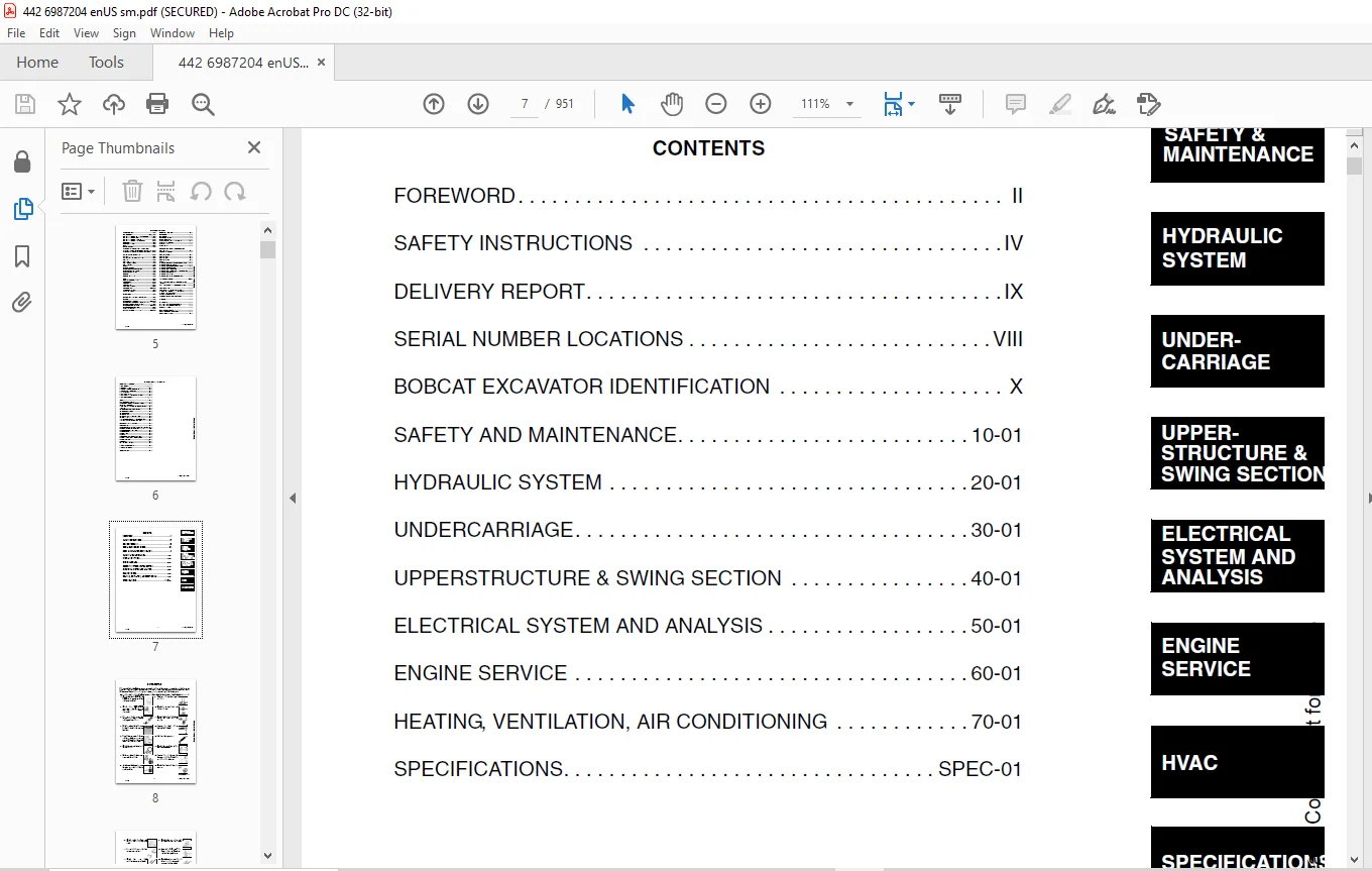
CONTENTS 7
FOREWORD 8
SAFETY INSTRUCTIONS 10
FIRE PREVENTION 12
Maintenance 12
Operation 12
Electrical 12
Hydraulic System 12
Fueling 12
Starting 12
Spark Arrestor Exhaust System 12
Welding And Grinding 13
Fire Extinguishers 13
SERIAL NUMBER LOCATIONS 14
Excavator Serial Number 14
Engine Serial Number 14
DELIVERY REPORT 15
SAFETY AND MAINTENANCE 17
LIFTING AND BLOCKING THE EXCAVATOR 19
Procedure 19
LIFTING THE EXCAVATOR 21
Procedure 21
OPERATOR CAB 23
Description 23
Entering And Exiting The Excavator 23
Raising And Lowering The Left Console 23
Emergency Exit 24
TRANSPORTING THE EXCAVATOR 25
REAR COVER 27
Opening And Closing The Rear Cover 27
RIGHT SIDE COVER 29
Opening And Closing The Right Side Cover 29
SERVICE SCHEDULE 31
AIR CLEANER 33
Daily Check 33
Replacing The Filters 33
FRESH AIR FILTER 35
Removal And Installation 35
COOLING SYSTEM 37
Cleaning The Cooling System 37
Checking Coolant Level 37
Replacing The Coolant 38
FUEL SYSTEM 41
Fuel Specifications 41
Filling The Fuel Tank 41
Pre-Filter Removal And Installation 42
Fuel Filter Removal And Installation 42
Draining The Fuel Tank 42
ENGINE LUBRICATION SYSTEM 45
Checking Engine Oil 45
Oil Chart 45
Replacing Oil And Filter 45
HYDRAULIC SYSTEM 47
Checking And Adding Hydraulic Oil 47
Replacing The Hydraulic Oil 48
Hydraulic Filter Removal 49
Hydraulic Filter Installation 50
Diagnostic Couplers 52
LUBRICATION OF THE EXCAVATOR 53
TRAVEL MOTOR 57
Checking Oil Level 57
Draining The Travel Motor 57
ALTERNATOR BELT 59
Adjusting Belt Tension 59
FAN/FUEL PUMP BELT 61
Adjusting Belt Tension 61
AIR CONDITIONING COMPRESSOR BELT 63
Adjusting Belt Tension 63
CAB TILT PROCEDURE 65
Installing The Cab Tilt Hinges 65
Tilting The Cab 66
HYDRAULIC SYSTEM 73
HYDRAULIC / HYDROSTATIC SCHEMATICS 79
HYDRAULIC SYSTEM INFORMATION 81
Troubleshooting Chart 81
Description 86
BOOM CYLINDER 89
Testing 89
Removal And Installation 91
Parts Identification 95
Disassembly 96
Assembly 101
ARM CYLINDER 107
Testing 107
Removal And Installation 107
Parts Identification 111
Disassembly 112
Assembly 117
BOOM OFFSET CYLINDER 123
Testing 123
BOOM OFFSET CYLINDER 126
Removal And Installation 126
Parts Identification 130
Disassembly 131
Assembly 135
BUCKET CYLINDER 143
Testing 143
Removal And Installation 143
Parts Identification 147
Disassembly 148
Assembly 152
BLADE CYLINDER 159
Testing 159
Removal And Installation 160
Parts Identification 162
Disassembly 163
Assembly 168
RELIEF VALVES 175
Description 175
Testing The Three Spool Control Valve Main Relief Valve 176
Adjusting The Three Spool Control Valve Main Relief Valve 176
PORT RELIEF VALVES 177
Adjustment Procedure 177
PRESSURE REDUCING VALVE 179
Description 179
Testing 179
Adjustment 180
DUMP VALVE 181
Description 181
Testing 181
Adjustment 181
Removal And Installation 182
Parts Identification 183
Disassembly And Assembly 184
SIX SPOOL HYDRAULIC CONTROL VALVE 189
Removal And Installation 189
Control Valve Identification 193
Disassembly And Assembly 194
Left Travel And Right Travel Valve Section Disassembly And Assembly 197
Boom, Arm, Bucket And Auxiliary Valve Section Disassembly And Assembly 200
Inlet Valve Section Disassembly And Assembly 205
THREE SPOOL HYDRAULIC CONTROL VALVE 207
Removal And Installation 207
Parts Identification 209
Disassembly And Assembly 210
Boom Offset And Blade Valve Section Disassembly And Assembly 212
Inlet/Upperstructure Swing Valve Section Disassembly And Assembly 216
HYDRAULIC PISTON PUMP 221
Hydraulic Pump Work Sheet 221
Testing Information 224
Pump Testing 225
Load Sense Relief Valve Adjustment 228
Removal And Installation 233
Coupler Removal And Installation 235
Torque Limiter Valve Parts Identification 236
Torque Limiter Valve Removal and Installation 237
Torque Limiter Valve Disassembly 238
Torque Limiter Valve Assembly 242
Initial Torque Limiter Valve Setting 246
Pump Control Parts Identification 248
Pump Control Removal And Installation 249
Pump Control Disassembly And Assembly 250
Parts Identification 255
Disassembly 256
Assembly 265
HYDRAULIC GEAR PUMP 275
Removal And Installation 275
Parts Identification 277
Disassembly 278
Assembly 281
ACCUMULATOR 285
Description 285
Removal And Installation 285
TRAVEL MOTOR 287
Removal And Installation 287
Parts Identification 288
Disassembly 289
Assembly 306
SWIVEL JOINT 325
Removal And Installation 325
Parts Identification 327
Disassembly And Assembly 328
SWING MOTOR 331
Removal And Installation 331
Parts Identification 333
Disassembly 334
Assembly 340
SWING MOTOR DRIVE CARRIER 347
Removal And Installation 347
Parts Identification 349
Disassembly 350
Assembly 359
SWING BRAKE VALVE 373
Removal And Installation 373
Parts Identification 374
Disassembly And Assembly 375
SWING BRAKE RELEASE VALVE 377
Removal And Installation 377
SWING BRAKE RELEASE VALVE (CONT’D) 378
Parts Identification 378
Disassembly And Assembly 379
JOYSTICK CONTROL PATTERN SELECTOR VALVE 381
Removal And Installation 381
Parts Identification 382
Disassembly And Assembly 383
JOYSTICK LOCKOUT/TWO SPEED VALVE 385
Removal And Installation 385
Parts Identification 387
Disassembly And Assembly 388
RIGHT CONTROL LEVER (JOYSTICK) 393
Testing 393
Handle Removal And Installation 394
Removal And Installation 395
Parts Identification 397
Disassembly And Assembly 398
LEFT CONTROL LEVER (JOYSTICK) 403
Testing 403
Handle Removal And Installation 404
Removal And Installation 405
Parts Identification 407
Disassembly and Assembly 408
TRAVEL LEVER/FOOT PEDAL VALVE 413
Left Travel Lever/Foot Pedal Valve Removal And Installation 413
Right Travel Lever/Foot Pedal Valve Removal And Installation 414
Parts Identification 416
Disassembly And Assembly 417
HYDRAULIC FILTER MOUNT 421
Removal And Installation 421
HYDRAULIC RESERVOIR 423
Removal And Installation 423
OIL COOLER 429
Description 429
SECONDARY FRONT AUXILIARY VALVE 431
Removal And Installation 431
Parts Identification 432
Disassembly And Assembly 433
AUXILIARY HYDRAULIC FLOW CONTROL/ HYDRAULIC BREAKER APPLICATION VALVE 437
Removal And Installation 437
AUXILIARY HYDRAULIC FLOW CONTROL/HYDRAULIC BREAKER APPLICATION VALVE (CONT’D) 438
Parts Identification 438
Disassembly And Assembly 439
BLADE VALVE 443
Removal And Installation 443
Parts Identification 444
Disassembly And Assembly 445
BLADE FLOAT VALVE 449
Removal And Installation 449
Parts Identification 450
Disassembly And Assembly 451
BOOM OFFSET VALVE 455
Removal And Installation 455
Parts Identification 456
Disassembly And Assembly 457
BOOM LOAD HOLDING VALVE 463
Removal And Installation 463
Parts Identification 464
Disassembly 465
Assembly 472
OIL TEMPERATURE REGULATOR 479
Description 479
Removal And Installation 479
AUXILIARY HYDRAULICS SELECTOR VALVE 481
Removal And Installation 481
HYDRAULIC PISTON PUMP DRIVE COUPLER 483
Removal And Installation 483
UNDERCARRIAGE 485
BLADE 487
Removal And Installation 487
TRACKS 489
Track Lug Height 489
Rubber Track Clearance 490
Steel Track Clearance 491
Track Adjustment 492
Rubber Track Removal And Installation 494
TRACK FRAME 497
Disassembly And Assembly 497
Drive Sprocket Removal And Installation 500
TRACK IDLER 501
Parts Identification 501
Disassembly 502
Assembly 506
UPPER TRACK ROLLER 513
Parts Identification 513
Disassembly 514
Assembly 516
LOWER TRACK ROLLER 521
Parts Identification 521
Disassembly 522
Assembly 525
GREASE CYLINDER 531
Parts Identification 531
Disassembly 532
Assembly 533
TRACK DAMAGE IDENTIFICATION 535
Cutting Of Steel Cords 535
Abrasion Of Embedded Metals 536
Separation Of Embedded Metals 537
Separation Of Embedded Metals Due To Corrosion 538
Cuts On The Lug Side Rubber 539
Cracks On The Lug Side Rubber Due To Fatigue 540
Lug Abrasion 541
Cracks And Cuts On The Lug Side Rubber 542
Abrasion Of The Track Roller Side 543
Cuts On The Edges Of Track Roller Side 544
UPPERSTRUCTURE & SWING SECTION 547
UPPERSTRUCTURE 549
Removal And Installation 549
Swing Bearing Removal And Installation 554
CAB 557
Removal And Installation 557
Door Removal And Installation 563
Front Window Removal And Installation 564
Front Window Gas Strut Removal And Installation 569
Front Window Pivot Frame Removal And Installation 570
Lower Front Widow Removal And Installation 571
Door, Left Side, Right Side And Rear Window Removal 572
Door, Left Side, Right Side And Rear Window Installation 573
Cab Visor Removal And Installation 575
Top Window Removal And Installation 576
SEAT AND SEAT MOUNT 577
Removal And Installation 577
RIGHT CONSOLE 579
Description 579
LEFT CONSOLE 581
Removal And Installation 581
Disassembly And Assembly 586
Console Lockout Switch Removal And Installation 588
ENGINE SPEED CONTROL 589
Removal And Installation 589
Disassembly And Assembly 591
CONTROL LEVERS 593
Description 593
FUEL TANK 595
Removal And Installation 595
HORN 599
Removal And Installation 599
SWING FRAME 601
Removal And Installation 601
Bushing Removal And Installation 605
FLOOR MAT 607
Removal And Installation 607
BOOM 609
Removal And Installation 609
Bushing Removal And Installation 616
ARM 617
Removal And Installation 617
Bushing Removal And Installation 620
BUCKET 621
Removal And Installation 621
REAR COVER 623
Removal And Installation 623
RIGHT SIDE COVER 625
Removal And Installation 625
COUNTERWEIGHT 629
Removal And Installation 629
ELECTRICAL SYSTEM AND ANALYSIS 633
ELECTRICAL SCHEMATICS 635
ELECTRICAL SYSTEM INFORMATION 640
Troubleshooting Chart 640
Description 641
Fuse And Relay Location 642
BATTERY 646
Servicing 646
Removal And Installation 647
Using A Booster Battery (Jump Starting) 649
ALTERNATOR 652
Removal And Installation 652
Parts Identification 654
Alternator Identification 655
Charging System Check 655
Rectifier Continuity (Diode) Test 657
Disassembly 659
Stator Continuity Test 665
Stator Ground Test 665
Rotor Continuity Test 665
Rotor Ground Test 666
Capacitor Continuity Test 666
Assembly 667
STARTER 674
Removal And Installation 674
Parts Identification 675
Disassembly 676
Inspection And Repair 684
Assembly 686
FRONT CAB LIGHT 696
Removal And Installation 696
Disassembly And Assembly 697
TWO SPEED SWITCH 700
Removal And Installation 700
FUEL LEVEL SENDER 702
Removal And Installation 702
WIPER MOTOR 704
Removal And Installation 704
BATTERY DISCONNECT SWITCH 706
Removal And Installation 706
INSTRUMENT PANEL 708
Removal And Installation 708
E-Prom Information 709
OIL TEMPERATURE COMPONENTS 710
Sensor Testing 710
Gauge Testing 710
ENGINE SERVICE 712
TROUBLESHOOTING 714
Chart 714
MUFFLER 716
Removal And Installation 716
AIR CLEANER 718
Removal And Installation 718
RADIATOR/OIL COOLER 720
Removal And Installation 720
ENGINE COMPONENTS AND TESTING 728
Engine Compression Checking 728
Checking The Manifold Heater 730
Manifold Heater Removal And Installation 731
Fuel Shutoff Solenoid Checking 732
Fuel Shutoff Solenoid Removal And Installation 733
Fuel Injection Pump Removal 734
Fuel Injection Pump Timing 736
Fuel Injection Pump Installation 737
Fuel Injector Removal And Installation 740
Fuel Injector, Checking 741
Fuel Injector Disassembly 742
Fuel Injector Assembly 743
Timing Belt Inspection 745
Timing Belt Removal 746
Timing Belt Installation 748
Valve Clearance Adjustment 754
Valve Timing, Checking 755
Aneroid Device 757
ENGINE 762
Removal And Installation 762
FLYWHEEL 768
Removal And Installation 768
Flywheel Ring Gear 769
RECONDITIONING THE ENGINE 770
Deutz Engine Tools Identification Chart 770
Disassembly 771
Assembly 778
Cylinder, Checking 796
Camshaft Bearing, Checking 797
Camshaft Bearing, Removal And Installation 798
Control Rod Guide Bushing Removal 799
Control Rod Guide Bushing Installation 801
Rear Cover Seal Removal And Installation 806
Crankshaft, Checking 808
Connecting Rod, Checking 810
Piston, Checking 813
Piston Pin, Checking 814
Piston Rings Installation 815
Piston Installation On The Connecting Rod 816
Cylinder Head Disassembly 817
Valves, Checking 818
Valve Clearance Adjustment 819
Cylinder Head Assembly 820
Rocker Arm And Bracket, Checking 822
Front Cover Disassembly 823
Front Cover Assembly 829
Turbo Charger Removal and Installation 839
Crankshaft Gear Mounting Bolt Torque Procedure 842
HEATING, VENTILATION, AIR CONDITIONING 844
EVAPORATOR UNIT 846
Removal And Installation 846
Disassembly And Assembly 849
Evaporator Removal And Installation 851
Fan Removal And Installation 852
Switch Removal And Installation 852
HEATER UNIT 854
Removal And Installation 854
Disassembly And Assembly 858
HEATER FAN 864
Removal And Installation 864
Resistor Removal And Installation 866
AIR CONDITIONING FAN 868
Removal And Installation 868
Switch Removal And Installation 868
HEATER VALVE 870
Removal And Installation 870
AIR CONDITIONING SYSTEM FLOW 873
Principles 873
Chart 874
COMPONENTS 876
Identification 876
SAFETY 880
Safety Equipment 880
REGULAR MAINTENANCE 882
Heater Air Filter 882
Air Conditioning Compressor Belt 882
Cleaning The Condenser 883
BASIC TROUBLESHOOTING 884
Poor A/C Performance 884
Compressor Drive Belt Inspection 885
Cleaning The Heater Coil 886
Cleaning The A/C Evaporator Coil 886
Checking The Electrical System 887
Engine Coolant Bypassing The Heater Valve 896
GENERAL AIR CONDITIONING SERVICE GUIDELINES 898
Compressor Oil 898
Compressor Oil Check 898
Component Replacement And Refrigeration Leaks 900
SYSTEM TROUBLESHOOTING CHART 902
Blower Motor 902
Gauge Pressure Related Troubleshooting 903
TEMPERATURE/PRESSURE 906
Chart 906
AIR CONDITIONING SERVICE 908
Chart 908
SYSTEM CHARGING AND RECLAMATION 910
Reclamation Procedure 910
COMPRESSOR 914
Removal And Installation 914
Compressor Clutch Disassembly And Assembly 915
CONDENSOR 918
Removal And Installation 918
RECEIVER/DRYER 920
Removal And Installation 920
PRESSURE SWITCH 922
Removal And Installation 922
HEATER COIL 924
Removal And Installation 924
THERMOSTAT 926
Removal And Installation 926
SPECIFICATIONS 928
HYDRAULIC EXCAVATOR SPECIFICATIONS 930
Excavator Machine Dimensions 930
Performance 931
Controls 931
Engine 931
Electrical 932
Hydraulic System 932
Hydraulic Cycle Times 932
Swing System 932
Hydraulic Cylinders 933
Drive System 933
Brake 933
Undercarriage 933
Track 933
Capacities 933
ENGINE SPECIFICATIONS 934
General 934
Fuel System 934
Valve, Valve Guide And Seat Insert 934
Piston And Rings 935
Connecting Rod 935
Cylinder Head And Block 935
Crankshaft And Main Bearings 936
Camshaft And Bearings 936
Oil Pump 936
Governor 936
ENGINE BOLT TORQUE 938
Specifications 938
EXCAVATOR BOLT TORQUE 940
Specifications 940
TORQUE SPECIFICATIONS FOR BOLTS 942
Torque For General SAE Bolts 942
Torque For General Metric Bolts 942
HYDRAULIC FLUID SPECIFICATIONS 944
Specifications 944
FUEL, COOLANT AND LUBRICANTS 946
Chart 946
CONVERSIONS 948
Decimal And Millimeter Equivalents 948
U S To Metric Conversion 949
SERVICE MANUAL REVISION 950
Revision No: 442 – 1 950
IMAGES PREVIEW OF THE MANUAL:
Questions? Email us: [email protected]
https://vimeo.com/841417059?share=copy
PLEASE NOTE:
- This is the same manual used by the DEALERSHIPS to SERVICE your vehicle.
- The manual can be all yours – Once payment is complete, you will be taken to the download page from where you can download the manual. All in 2-5 minutes time!!
- Need any other service / repair / parts manual, please feel free to contact us at heydownloadss @gmail.com . We may surprise you with a nice offer
S.M