Bobcat 540 543 Loader Service Manual 6566181 (6-12) – PDF DOWNLOAD
$28.95
Bobcat 540 543 Loader Service Manual 6566181 (6-12) – PDF DOWNLOAD
540 (S/N 501011999 & Below)
543 (S/N 501111999 & Below)
Description
Bobcat 540 543 Loader Service Manual 6566181 (6-12) – PDF DOWNLOAD
FILE DETAILS:
Bobcat 540 543 Loader Service Manual 6566181 (6-12) – PDF DOWNLOAD
Language : English
Pages : 256
Downloadable : Yes
File Type : PDF
DESCRIPTION:
Bobcat 540 543 Loader Service Manual 6566181 (6-12) – PDF DOWNLOAD
540 (S/N 501011999 & Below)
543 (S/N 501111999 & Below)
FOREWORD:
This Service Manual gives the instructions for correct servicing, adjustment and overhauling of
the Bobcat loader Hydraulic/Hydrostatic System, Drive System, Main Frame, Electrical System
and Engine Service.
Make reference to the Operator’s Manual for operating instructions (Starting, Daily Checks,
Loader Operation, etc.).
A general inspection of the following items must be made when the Bobcat loader has had
service or repair.
1. Check hydraulic/hydrostatic fluid level, engine oil level and fuel supply.
2. Inspect for any sign of fuel, oil or hydraulic fluid leaks.
3. Lubricate the loader.
4. Check the condition of the battery(ies) and the cables.
5. Inspect the air cleaner system for damage or leaks.
6. Check the warning lights to see if they light.
7. Check the tires for wear and pressure.
8. Check the Bob–Tach for wear and see if the wedges are damaged.
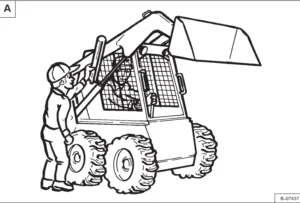
9. Check the safety items for condition (Operator Guard, Seat Belt, Seat Bar, Safety Signs
(Decals), Safety Treads, etc.).
10. Make an inspection for loose or broken parts or connections.
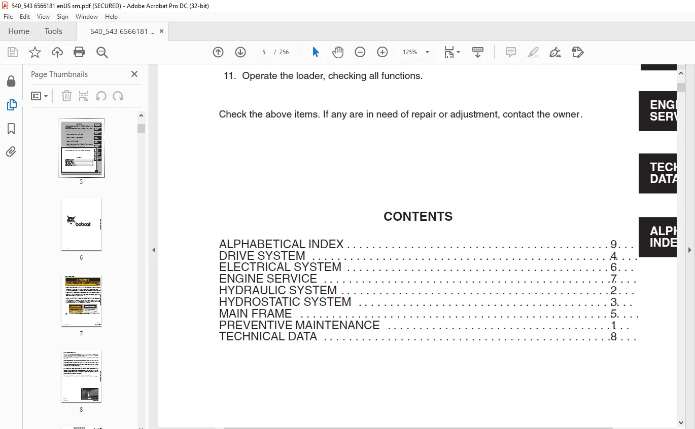
11. Operate the loader, checking all functions.
TABLE OF CONTENTS:
Bobcat 540 543 Loader Service Manual 6566181 (6-12) – PDF DOWNLOAD
MAINTENANCE SAFETY 3
CONTENTS 5
FOREWORD 5
SAFETY INSTRUCTIONS 7
PREVENTIVE MAINTENANCE 9
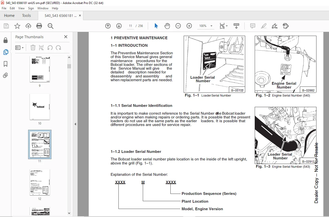
INTRODUCTION 11
Serial Number Identification 11
Loader Serial Number 11
Engine Serial Number 11
Pre–Delivery Inspection 11
Thirty Hour Inspection 12
SERVICE SCHEDULE 13
ENGINE SERVICE (General) 14
Air Cleaner Service 14
Fuel System 15
Engine Lubrication System 16
Replacement Of The Engine Oil And Filter 16
Engine Cooling System 17
ELECTRICAL SYSTEM 18
Electrical System Service 18
Using An Extra Battery (Booster Starting) 18
Installing New Battery 20
HYDRAULIC/HYDROSTATIC FLUID 21
Replacing The Hydraulic/Hydrostatic Filter 21
Checking And Adding Hydraulic/Hydrostatic Fluid 21
Removing The Hydraulic/Hydrostatic Fluid 22
FINAL DRIVE TRANSMISSION (Chaincase) 23
Checking Chaincase Fluid 23
SPARK ARRESTOR MUFFLER 23
Cleaning The Spark Arrestor Muffler 23
OPERATOR GUARD 24
LUBRICATION OF THE LOADER 24
TRANSPORTING THE BOBCAT LOADER 25
Loading The Bobcat Loader 25
Fastening The Loader To TheTransport Vehicle 25
LIFT ARM STOP 26
STOPPING THE BOBCAT LOADER 26
HYDRAULIC SYSTEM 27
HYDRAULIC / HYDROSTATIC SCHEMATICS 29
TROUBLESHOOTING 39
HYDRAULIC SYSTEM INFORMATION 40
37° Flare Connections 40
Straight Thread O–Ring Fitting 40
Tubelines and Hoses 40
HYDRAULIC CONTROL VALVE 41
Relief Valve 41
Checking The Relief Valve 41
Removal Of The Relief Valve 42
Installation Of The Relief Valve 42
Removal Of The Hydraulic Control Valve 43
Disassembly Of The Hydraulic Control Valve 44
Detent Mechanism 45
Assembling the Hydraulic Control Valve 46
Installing the Hydraulic Control Valve 48
HYDRAULIC PUMP 48
Checking Output Of The Hydraulic Pump 49
Removal Of The Hydraulic Pump 49
Disassembly Of The Hydraulic Pump 50
Inspection Of The Hydraulic Pump 51
Assembling The Hydraulic Pump 51
Installing The Hydraulic Pump 53
Start–Up Procedure For The Hydraulic Pump 53
LIFT CYLINDERS 53
Checking The Lift Cylinders 53
Removing The Lift Cylinder 54
Disassembly Of The Hydraulic Cylinder 55
Assembly Of The Hydraulic Cylinder 56
Installation Of The Lift Cylinder 58
TILT CYLINDER 59
Checking The Tilt Cylinder 59
Removing The Tilt Cylinder 60
Installation Of The Tilt Cylinder 61
HYDRAULIC/HYDROSTATIC RESERVOIR 61
Removing The Hydraulic/Hydrostatic Reservoir 61
Installation Of The Hydraulic/Hydrostatic Reservoir 62
OIL COOLER 62
Removing The Oil Cooler (540) 62
Installation Of The Oil Cooler (540) 63
Removing The Oil Cooler (543) 63
Installing The Oil Cooler (543) 64
10 MICRON FILTER BY–PASSVALVE 64
Removing The By–Pass Valve 64
Installation Of The By–Pass Valve 65
CONTROL PEDAL, LINKAGE AND LOCKS 65
Removing The Control Pedal 65
Adjusting The Control Pedal 66
Pedal Lock Linkage 66
HYDROSTATIC SYSTEM 69
TROUBLESHOOTING 71
HYDROSTATIC SYSTEM INFORMATION 72
High Pressure Relief Replenishing Valves Function 72
STEERING LEVERS 73
Removing Steering Levers 73
Repairing The Steering Levers 74
Installing The Steering Levers 74
STEERING LINKAGE 75
Adjustment Of The Steering Linkage 75
Removing The Steering Linkage 76
Repairing The Pintle Lever 77
Installing The Steering Linkage 77
PORT BLOCK 78
Removing The Port Block 78
Installing The Port Block 78
By–Pass Valve 79
HYDROSTATIC MOTOR 79
Removing The Hydrostatic Motor 79
Disassembly Of The Hydrostatic Motor 81
Inspection Of The Hydrostatic Motor 83
Assembling The Hydrostatic Motor 84
Installing The Hydrostatic Motor 87
Start–Up Procedure For The Hydrostatic Motor 87
HYDROSTATIC PUMP 88
Checking The High Pressure Relief Replenishing Valves 88
Checking The Charge Pressure 89
Cold Weather By–Pass Valve 89
Removing The Hydrostatic Pumps 90
Disassembly Of The Hydrostatic Pumps 91
Inspection Of The Hydrostatic Pumps 95
Assembling The Hydrostatic Pumps 96
Installing the Hydrostatic Pumps 99
Hydrostatic Pump Start–Up Procedure 100
DRIVE SYSTEM 103
BRAKES 105
Parking Brake Adjustment 105
Parking Brake Removal 105
Parking Brake Inspection 107
Parking Brake Installation 107
FINAL DRIVE CHAINS 109
Remove The Drive Chain(s) 109
Installing The Drive Chain(s) 110
AXLES AND BEARINGS 111
Removing Axle(s) and Bearings 111
Assembly Of The Axle 112
Axle And Bearing Installation 113
CHAINCASE FLUID 114
Replacing Chaincase Fluid 114
MAIN FRAME 115
OPERATOR GUARD 117
Raising The Operator Guard 117
Lowering The Operator Guard 117
Jumper Start Switch 118
Removing The Operator Guard 118
Installing The Operator Guard 119
LIFT ARMS 119
Removing The Lift Arms 119
Installing The Lift Arms 120
BOB–TACH 121
Removing The Bob–Tach 121
Disassembly Of The Bob–Tach 122
Assembly Of The Bob–Tach 123
Installing The Bob–Tach 124
REAR DOOR 125
Removing The Rear Door (Early Model) 125
Removing The Rear Door (Later Models) 125
Installing The Rear Door 126
Adjusting The Rear Door Latch 126
FUEL TANK 127
Removing The Fuel Tank 127
Installing The Fuel Tank 127
ELECTRICAL SYSTEM 129
ELECTRICAL SCHEMATICS 132
TROUBLESHOOTING 139
ELECTRICAL SYSTEM INFORMATION 140
Electrical Circuitry 140
Safety Procedures For The Batteries 140
Precautions For The Alternator 141
BATTERY 141
Removing The Battery 141
Installing The Battery 142
WIRE HARNESS FOR THE OPERATOR GUARD 142
Removing The Wire Harness For The Operator Guard 142
Installing The Wire Harness For The Operator Guard 143
WIRE HARNESS FOR THE ENGINE 143
ALTERNATOR SYSTEM (540) 144
Checking the A C Voltage 144
Replacement Of The Stator 144
ALTERNATOR SYSTEM (543) 144
Belt Adjustment For The Alternator 144
Checking The Alternator 145
Removing The Alternator 146
Repairing The Alternator 147
Installing The Alternator 148
STARTER (540) 149
Checking The Starter 149
Removing The Starter 149
Repairing The Starter 149
STARTER (543) 150
Checking The Starter 150
Removing The Starter 150
Repairing The Starter 151
Installing The Starter 153
ENGINE SERVICE 155
540 KOHLER ENGINE SERVICE 157
TROUBLESHOOTING 159
CHECKS & ADJUSTMENTS 161
Oil Pressure 161
Valve Clearance 161
Compression 162
Throttle And Governor Linkage 162
Ignition System 163
Spark Plugs 163
CARBURETOR & FUEL SHUT–OFF SOLENOID 164
Removing The Carburetor 164
Disassembly And Inspection Of The Carburetor 164
Assembly Of The Carburetor 164
Fuel Shut–off Solenoid 165
GOVERNOR 165
Removing The Governor 165
Installing The Governor 165
ENGINE AND HEAT SHIELD 166
Removing The Engine 166
Installation Of The Engine 167
Removing The Heat Shield 167
Installing The Heat Shield 168
RECONDITIONING THE VALVES 168
Repair Of The Valves And Guides 168
TIMING COVER, TIMING GEARS AND CAMSHAFT 169
Timing Cover 169
Timing Gears 169
Camshaft And Tappets 170
OIL PUMP AND RELIEF VALVE 170
Relief Valve 170
Oil Pump 170
Adjusting Gear Clearance For The Oil Pump 170
PISTONS, RODS AND CRANKSHAFT 171
Removing Pistons, Rods And Crankshaft 171
Crankshaft Bearing And End Play 172
CYLINDER HEAD 173
INTAKE AND EXHAUST MANIFOLD 173
FLYWHEEL 173
543 ISUZU ENGINE SERVICE 175
TROUBLESHOOTING 177
FUEL SYSTEM 179
Fuel Filter 179
Removing The Air From The Fuel System 179
Fuel Lift Pump 179
Removal Of The Fuel Injection Pump 180
Fuel Injection Pump Drive Gear 180
Installation And Timing Of The Fuel Injection Pump 181
Fuel Injection Pump Reservoir 181
Fuel Injector Nozzles 182
Removing The Fuel Injector Nozzles 182
Checking The Fuel Injector Nozzles 183
Disassembly Of The Fuel Injector Nozzle 184
Inspection Of The Fuel Injector Nozzle 184
Assembling The Fuel Injectors Nozzle 184
nstallation Of The Fuel Injector Nozzles 185
ENGINE, BLOWER HOUSING AND RADIATOR 185
Removing The Engine 187
Installing The Engine 188
Installing The Blower Housing 189
Removing The Radiator 190
Installation Of The Radiator 192
ENGINE OVERHAUL 193
Disassembly Of The Engine 193
ROCKER ARMS AND SHAFT 194
Disassembly Of The Rocker Arms 194
Inspection Of The Rocker Arms 195
CYLINDER HEAD 195
Disassembly Of The Cylinder Head 195
Inspection Of The Cylinder Head 196
Inspection Of The Combustion Chambers 196
Inspection And Correction Of The Valves & Guides 196
Inspection Of The Valve Springs 198
Inspection Of The Push Rods And Tappets 198
Installation Of The Hot Plugs 198
Assembly Of The Valve System 198
CYLINDER BLOCK 199
Inspection Of The Cylinder Block 199
Correction Of The Cylinder Bores 199
PISTONS AND PISTON RINGS 199
Disassembly Of The Piston And Rings 199
Inspection Of The Pistons 200
Inspection Of The Connecting Rods & Bearings 200
Assembly Of The Piston & Connecting Rod 201
Inspection Of The Connecting Rod Bearings 201
CRANKSHAFT 202
Inspection Of The Crankshaft And Bearings 202
CAMSHAFT 202
Inspection Of The Camshaft 202
TIMING GEAR 203
Inspection Of The Timing Gear 203
MANIFOLD ASSEMBLY 203
Inspection Of The Manifold Assembly 203
OIL PUMP AND OIL FILTER ASSEMBLY 203
Disassembly Of The Oil Pump 203
Inspection Of The Oil Pump 204
Oil Filter Assembly 204
Inspection Of The Oil Filter Assembly 204
WATER PUMP 204
Disassembly Of The Water Pump 204
Inspection Of The Water Pump 205
Assembly Of The Water Pump 205
ASSEMBLY OF THE ENGINE 206
ENGINE FLYWHEEL 209
Removing The Flywheel 209
Installing The Flywheel 209
TECHNICAL DATA 211
540 LOADER SPECIFICATIONS 213
Specifications 213
Engine 213
Loader Hydraulics 214
Electrica 214
Drive System 214
Capacities 214
Tires 214
543 LOADER SPECIFICATIONS 215
Specifications 215
Engine 215
Loader Hydraulics 216
Electrical 216
Drive System 216
Capacities 216
Tires 216
ENGINE SPECIFICATIONS 217
540 LOADER (KOHLER) 217
Engine (General) 217
Cylinder Bore 217
Crankshaft 217
Camshaft 217
Connecting Rod 217
Piston, Pin & Rings 217
Valves, Guides & Tappets 217
Engine Torque 218
543 LOADER (ISUZU) 219
Cylinder Block 219
Cylinder Head 219
Piston 219
Piston Ring 219
Connecting Rod 219
Crankshaft 219
Camshaft 219
Timing Gear 219
Valve 220
Valve Spring 220
Tappet 220
Oil Pump and Relief Valve 220
Water Pump 220
Fuel Lift Pump 220
Fuel Injector 220
Engine Torque 221
TORQUE SPECIFICATIONS 222
Engine Group – 540 Loader 222
Engine Group – 543 Loader 223
Engine Group – 543 Loader 224
Seat Bar, Fuel Tank & Panel Group 225
Steering Levers, Linkage & Pedal Group 226
Mainframe Group 228
Hydrostatic Group – 540 Loader 229
Hydrostatic Group – 543 Loader 230
Hydraulic Group 231
HYDRAULIC/HYDROSTATIC FLUID SPECIFICATIONS 232
Hydraulic/Hydrostatic Fluid 232
DECIMAL AND MILLIMETER EQUIVALENTS 233
U S TO METRIC CONVERSION 233
STANDARD TORQUE SPECIFICATIONS FOR BOLTS 234
ALPHABETICAL INDEX 235
SERVICE MANUAL REVISIONS 241
540–1 241
540–2 243
540–2 245
540–3 247
540–4 249
540–5 251
540–6 253
540-7 255
IMAGES PREVIEW OF THE MANUAL:
Need help? Contact: [email protected]
PLEASE NOTE:
- This is the same manual used by the DEALERSHIPS to SERVICE your vehicle.
- The manual can be all yours – Once payment is complete, you will be taken to the download page from where you can download the manual. All in 2-5 minutes time!!
- Need any other service / repair / parts manual, please feel free to contact us at heydownloadss @gmail.com . We may surprise you with a nice offer
S.V