Bobcat 630 631 632 Loader Service Manual 6556454 (6–12) – PDF DOWNLOAD
$28.95
Bobcat 630 631 632 Loader Service Manual 6556454 (6–12) – PDF DOWNLOAD
Description
Bobcat 630 631 632 Loader Service Manual 6556454 (6–12) – PDF DOWNLOAD
FILE DETAILS:
Bobcat 630 631 632 Loader Service Manual 6556454 (6–12) – PDF DOWNLOAD
Language : English
Pages : 286
Downloadable : Yes
File Type : PDF
TABLE OF CONTENTS:
Bobcat 630 631 632 Loader Service Manual 6556454 (6–12) – PDF DOWNLOAD
MAINTENANCE SAFETY 3
CONTENTS 5
FOREWORD 5
PREVENTIVE MAINTENANCE 7
INTRODUCTION 9
Symbols 9
Serial Number Identification 9
Loader Serial Number 9
Engine Serial Number 9
Pre–Delivery Inspection 10
30 Hour Inspection 10
SERVICE INTERVALS 11
BOBCAT SERVICE SCHEDULE* 11
ENGINE SERVICE 12
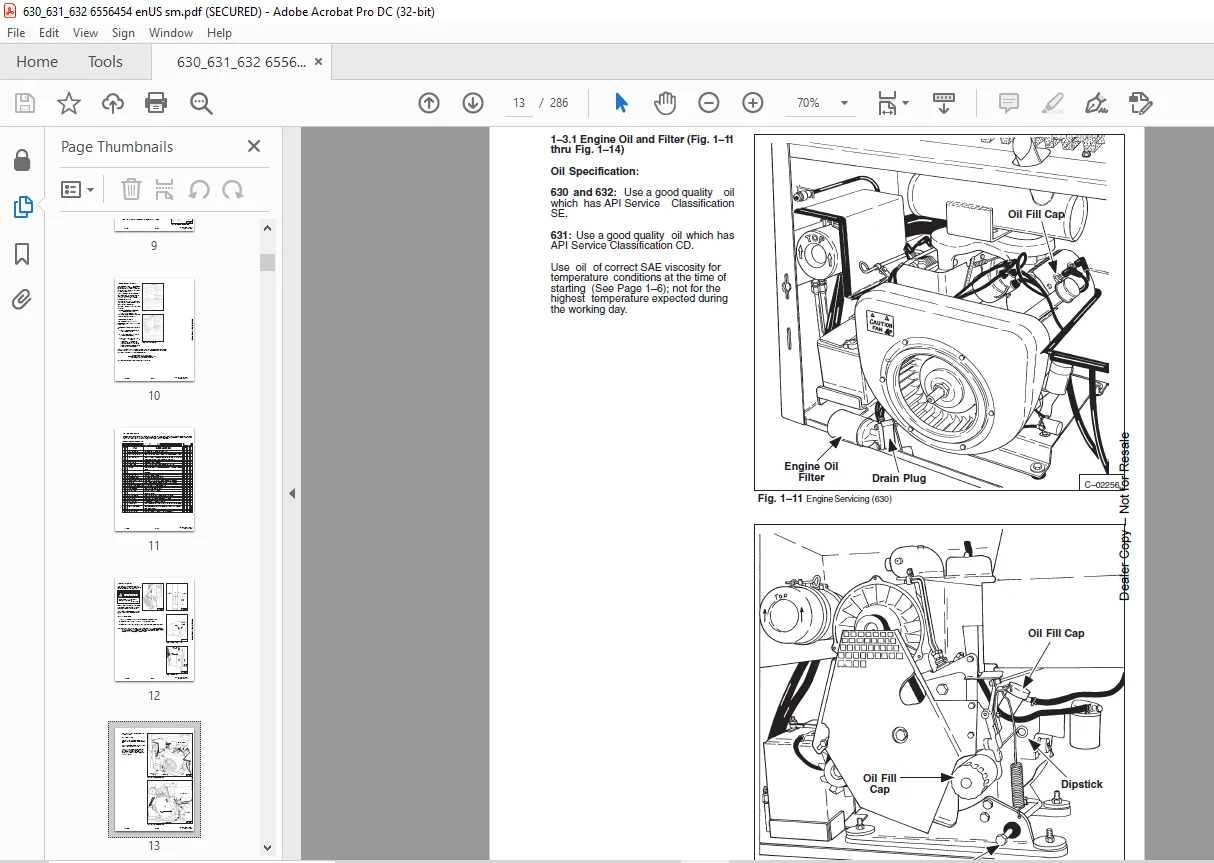
Engine Oil And Filter 13
Checking Oil 14
Adding Oil 14
Replacement Oil And Filter 14
Crankcase Breather 15
Air Cleaner System 15
Fuel System (630, 632) 16
Fuel Filter 16
Fuel System (631) 17
Fuel Pump 17
Carburetor 17
Carburetor Adjustment 18
Idle Adjusting Needle 18
Throttle Idle Adjustment 18
Fuel Shut–Off 18
Engine Cooling System 18
Removing Coolant From System (632) 19
Engine Electrical System (630, 631 & 632) 19
Using An Extra Battery 21
Installing New Battery 22
Ignition System (630 & 632) 22
Making Adjustment of Spark Plug Gap 22
Making Adjustment of Point Gap 22
HYDRAULIC FLUID AND FILTER 22
Fluid 22
Filter 23
TRANSMISSION AND DRIVE SYSTEM 23
Drive Chains 23
Brakes 23
Fluid 23
Tires 23
Tire Rotation 24
LOADER LUBRICATION 24
BOB–TACH AND PIVOT PINS 24
THE ENGINE MUFFLER 25
HYDRAULIC SYSTEM 27
HYDRAULIC / HYDROSTATIC SCHEMATICS 29
HYDRAULIC CIRCUIT 55
HYDRAULIC SYSTEM INFORMATION 55
Keeping Bobcat Clean 55
37° Flare Connections 55
Tubelines And Hoses 55
Straight Thread O–Ring Connections 55
HYDRAULIC TROUBLESHOOTING 56
CONTROL VALVE 57
Removing Control Valve 57
Disassembly And Inspection Of Control Valve 57
Assembling Control Valve 57
Detent Spool Repair (Lift And Auxiliary Spools) 58
Relief Valve 58
Check Release Pressure 58
Relief Valve Removal and Replacement 58
Check Output of the Hydraulic Pump 59
HYDRAULIC PUMP 60
Checking Output Of Pump 60
Hydraulic Pump Replacement 60
HYDRAULIC CYLINDERS 60
Checking Lift Cylinders 60
Checking Tilt Cylinder 61
Removing Hydraulic Cylinder 61
Hydraulic Cylinder Repair 62
Disassembly 62
Assembly 63
Tilt Cylinder Spacer (3’’ Tilt Cylinder) 66
QUICK COUPLERS 66
Restriction in the Quick Couplers (Early Models Only) 66
HYDROSTATIC SYSTEM 67
HYDROSTATIC CIRCUIT 69
HYDROSTATIC TROUBLESHOOTING 69
STEERING LINKAGE ADJUSTMENT 72
REPLENISHING VALVE 73
Checking Replenishing Valves 73
BY–PASS VALVE 74
PUMP ASSEMBLY – REMOVAL AND INSTALLATION 74
Removing the Bronze Filter 74
HYDROSTATIC PUMP ASSEMBLY – REPAIR 75
Hydrostatic Pump Disassembly 75
Hydrostatic Pump Inspection 76
Yoke, Pintle Bearing, etc – Installation 77
#2 Pump Assembly 79
Assemble Rotating Group 79
Installing Rotating Group Into Housing 80
#1 Pump Assembly 80
Assemble Rotating Group 80
Install Rotating Group Into Housing 81
Installing Pumps to Manifold Block 81
HYDROSTATIC MOTORS (630 S/N 15375 & Below and 632 S/N 15320 & Below) 81
Removing The Hydrostatic Motors 82
Installing Hydrostatic Motors 83
Making The Special Tool For Holding Motor Sprockets 84
Hose Location 84
To Remove Air From The Hydrostatic System (S/N 12999 & Below) 85
To Remove Air From The Hydrostatic System (S/N 13000 & Above) 85
HYDROSTATIC MOTOR REPAIR (630 (S/N 15375 & Below) And 632 (S/N 15320 & Below) 86
Hydrostatic Motor Disassembly and Inspection 87
Hydrostatic Motor Assembly 88
Start–Up Procedure For The Hydrostatic Motor 91
HYDROSTATIC MOTOR REPAIR (630 – S/N 15376 & Above, 631 and 632 – S/N 15321 & Above) 92
Disassembly Of The Hydrostatic Motor 92
Hydrostatic Motor Inspection 95
Assembly Of The Hydrostatic Motor 96
Installing The Hydrostatic Motor 101
Start–Up Procedure For The Hydrostatic Motor 101
STEERING CONTROLS 101
Installing Steering Linkages – 630–S/N 15300 & Below; 631–S/N 12253 & Below; 632–S/N 15450 & Below; 101
Installing Steering Linkages; 630 (S/N 15301 & Above; 631 (S/N 12254 & Above); 632 (S/N 15451 & Above) 103
DRIVE SYSTEM 105
FINAL DRIVE 107
Drive Chains 107
AXLE AND BEARINGS 107
Axle Bearing Removal 107
Assembly And Installation 108
BRAKE INSTALLATION 108
MAIN FRAME 113
ROPS REMOVAL AND INSTALLATION 115
PIVOT PIN REPLACEMENT ON THE LIFT ARMS 115
BOB–TACH 116
Checking Bob–Tach Wedges 116
Bob–Tach Removal 116
Bob–Tach Installation 116
Bob–Tach Pins 116
Bob–Tach Over–Center Stop 116
MAIN FRAME TO UPRIGHT FRAME BOLTS 117
LIFT ARMS 117
ELECTRICAL SYSTEM 119
USING AN EXTRA BATTERY 131
ROPS ELECTRICAL SYSTEM (Harness P/N 6558859) 132
ROPS WIRING DIAGRAM (Harness P/N 6557492) 133
630 ENGINE ELECTRICAL SYSTEM (S/N 14999 & Below) (Harness P/N 6558862) 134
ENGINE WIRING DIAGRAM 630 (S/N 14999 & Below) (Harness P/N 6558862) 135
ENGINE ELECTRICAL SYSTEM 631 (S/N 4997 12999 & Below) 136
ENGINE WIRING DIAGRAM 631 (S/N 4997 12999 & Below) 137
ENGINE ELECTRICAL SYSTEM 138
ENGINE WIRING DIAGRAM 139
ELECTRICAL GENERAL INFORMATION 141
Troubleshooting The Flywheel Alternator (630) 141
PROBLEM: BATTERY OVERCHARGE 142
PROBLEM: LOW/NO CHARGE 142
To Check The Stator 142
To Check the Rectifier Module 143
To Check the Regulator Module 143
ELECTRICAL CIRCUIT (631, 632) 143
Electrical Troubleshooting 143
CHART A BATTERY HAS LOW CHARGE 144
CHART B BATTERY OVER–CHARGE 144
ROPS Electrical Connector 144
ALTERNATOR BELT ADJUSTMENT AND REPLACEMENT (631, 632) 145
Adjustment 145
Replacement 145
Check Condition of Battery And Cables 145
Check Alternator Wiring 145
Check Alternator Output 146
Check Regulator 146
ALTERNATOR SERVICE 146
Alternator Removal 146
Alternator Disassembly 146
Checking Rotor 147
Checking Diode Trio 147
Checking Rectifier 147
Alternator Assembly and Installation 148
STARTER 148
Checking Starter 148
Removing Starter 148
Starter Disassembly 148
Starter Cleaning and Inspection 149
Brush Replacement 150
Starter Assembly 150
Check Electrical Wiring 150
ENGINE SERVICE 151
WISCONSIN ENGINE (630) 153
TROUBLESHOOTING 155
ENGINE IGNITION SYSTEM 156
Distributor Maintenance 156
Timing Procedure 156
Spark Plugs 156
CARBURETOR SERVICE 157
Adjustments 157
Float Adjustment 157
Governor Adjustment 157
REMOVAL OF ENGINE 157
REMOVAL OF ACCESSORIES 158
REMOVAL OF FLYWHEEL 158
REMOVAL OF AIR HOUSING 158
REMOVAL OF CARBURETOR AND MANIFOLD 158
REMOVAL OF CYLINDER HEADS 158
REMOVAL OF CAMSHAFT 158
REMOVAL OF IDLER GEAR AND SHAFT 159
REMOVAL OF OIL PAN 159
REMOVAL OF OIL PUMP 159
REMOVAL OF PISTONS AND CONNECTING RODS 159
REMOVAL OF VALVE AND SEAT INSERTS 160
REMOVAL OF CYLINDER BLOCK 160
REMOVAL OF CRANKSHAFT 161
REMOVAL OF CAMSHAFT 161
REMOVAL OF VALVE TAPPETS 161
INSTALLATION OF VALVE TAPPETS 161
INSTALLATION OF CAMSHAFT 161
INSTALLATION OF CRANKSHAFT 161
Three Bearing Crankshaft 161
INSTALLATION OF CYLINDER BLOCKS 162
INSTALLATION OF PISTON RINGS 162
INSTALLATION OF VALVES AND SEAT INSERTS 162
INSTALLATION OF PISTONS AND CONNECTING RODS 162
INSTALLATION OF OIL PUMP 163
OIL PAN INSTALLATION 163
INSTALLATION OF IDLER GEAR AND SHAFT 164
INSTALLATION OF GEAR COVER 164
INSTALLATION OF CYLINDER HEAD 164
INSTALLATION OF CARBURETOR AND MANIFOLD ASSEMBLY 165
INSTALLATION OF AIR HOUSING 165
INSTALLATION OF FLYWHEEL 165
INSTALLATION OF ACCESSORIES 165
GOVERNOR SERVICE 165
DEUTZ ENGINE–FL411D (631) 167
TROUBLESHOOTING 169
Engine Mounts 170
FUEL SYSTEM 171
Fuel And Control Linkage Adjustment 171
Venting Air From Fuel System 171
Fuel Filter 172
Fuel Lift Pump 172
Fuel Injection Pump Checking 173
Removal Of Fuel Injection Pump 173
Fuel Injection Pump Service 173
To Install Fuel Injection Pump 173
Adjustment Of Fuel Delivery 174
FUEL INJECTION NOZZLES 175
Removal Of Fuel Injection Nozzles 175
Disassembly & Repair Of Fuel Injection Nozzles 175
Installation Of Fuel Injection Nozzles 175
ENGINE INFORMATION 175
ENGINE REMOVAL 175
BLOWER FAN 176
Removal 176
Installation 176
Disassembly 176
Assembly 176
CYLINDER HEAD AND VALVES 176
Removal 176
Disassembly 177
Repair and Assembly 177
Installation Of Cylinder Head 179
CYLINDERS, PISTONS, CONNECTING RODS 180
Assembly 181
OIL PUMP, FILTER HOUSING AND RELIEF VALVE 181
Oil Pump Removal 181
Installation 182
Oil Pressure Relief Valve 182
Filter Housing 182
ENGINE FRONT COVER 182
Removal 182
Disassembly & Inspection 182
Assembly 183
Installation 184
GOVERNOR 184
Removal and Disassembly 184
Assembly and Installation 185
CAMSHAFT (Engine Must Be Removed) 185
Removal 185
Installation 185
Crankshaft Removal 186
Crankshaft Inspection 186
Crankshaft Assembly 186
FLYWHEEL 187
DEUTZ ENGINE–F2L511 (631) 188
TROUBLESHOOTING 188
ENGINE MOUNTS 189
FUEL SYSTEM 189
Venting Air From Fuel System 190
Fuel Filters 190
Fuel Lift Pump 191
Removal Of Fuel Injection Pump 191
Removal Of Injection Pump 191
Fuel Injection Pump Service 191
To Install Fuel Injection Pump 191
Adjustment Of Fuel Delivery 193
FUEL INJECTION NOZZLES 194
Removal 194
Disassembly And Repair Of Injector (In Shop) 194
Installation Of Injector 194
ENGINE INFORMATION 195
ENGINE REMOVAL 195
BLOWER FAN 195
Removal Of Blower Fan 195
Installation 196
Disassembly 196
Assembly 196
CYLINDER HEAD AND VALVES 196
Removal And Disassembly 196
Repair And Assembly 197
Checking Piston Crown Clearance And Installation Of Cylinder Head 199
CYLINDER, PISTONS AND CONNECTING RODS 200
Assembly 201
OIL PUMP, FILTER HOUSING AND RELIEF VALVE 202
Oil Pump Removal 202
Installation 202
Oil Pressure Relief Valve 202
ENGINE FRONT COVER 202
Removal 202
Disassembly And Inspection 203
Assembly 203
Installation 204
GOVERNOR 205
Removal And Disassembly 205
Assembly And Installation 205
CAMSHAFT (Engine Must Be Out Of Machine) 206
Removal 206
Installation 206
Crankshaft Removal 206
Crankshaft Inspection 207
Crankshaft Assembly 207
FLYWHEEL 208
Installing Flywheel 208
ENGINE OIL COOLER 208
FORD ENGINE (632) 209
TROUBLESHOOTING 211
CHECKS AND ADJUSTMENTS 212
Engine Oil Pressure 212
Valve Clearance 212
Checking Engine Compression 213
Understanding The Results Of The Test 213
Carburetor, Throttle And Governor Adjustments 214
Ignition System 216
Coil To Coil Ground Voltmeter Test 216
Spark Plug Wires Resistance Test 216
Spark Plug Test 216
Distributor Tests 216
Dwell Angle Check 216
Spark Strength Tests 217
Ignition System Tests 217
Battery To Coil Voltmeter Test 217
Starting Ignition Circuit Voltmeter Test 217
Breaker Point Gap Adjustment 218
Ignition Timing 218
Timing Mark Locations 218
Initial Ignition Timing 218
CARBURETOR REPAIR 219
ENGINE DIAGNOSIS AND TESTING 219
Camshaft Lobe Lift 219
Crankshaft End Play 220
Flywheel Face Alignment Check 220
Camshaft End Play 220
ENGINE OVERHAUL 220
Cylinder Head 220
Valve Guides 220
Grinding Valve Seats 221
Valves 221
Grinding Valves 221
Select Fitting Of Valves 221
Camshaft Repair 221
Crankshaft 221
Reconditioning Crankshaft Journals 221
To Check Crankshaft Or Connecting Rod Bearings With Plastigage 221
Pistons, Pins And Rings 222
To Install Pistons 222
To Install Piston Rings 222
Installing Piston Pins 223
Valve Rocker Arm And/Or Shaft Assembly 223
Push Rods 223
Cylinder Block 223
Finishing Cylinder Walls 223
Cylinder Head 223
Cleaning 223
Inspection 223
Tappets 224
Cleaning 224
Inspection 224
Camshaft 224
Cleaning and Inspection 224
Crankshaft Inspection 224
Flywheel Inspection 224
Connecting Rods 224
Cleaning 224
Inspection 225
Pistons, Pins And Rings 225
Cleaning 225
Inspection 225
Main And Connecting Rod Bearings 225
Cleaning 225
Inspection 225
Cylinder Block 225
Cleaning 225
Inspection 226
OIL PUMP 226
Cleaning 226
Inspection 226
REMOVAL OF ENGINE 226
VALVE ROCKER ARM COVER, ROCKER ARM AND/OR SHAFT 227
Removal And Disassembly 227
Installation 227
VALVE PUSHROD 227
Removal 227
Installation 228
INTAKE MANIFOLD 228
Removal 228
Installation 228
CYLINDER HEAD 228
Removal 228
Installation 229
VALVE SPRING, RETAINER AND STEM SEAL (CYLINDER HEAD REMOVED) 230
Removal 230
Installation 230
VALVE SPRING, RETAINER AND STEM SEAL (CYLINDER HEAD INSTALLED) 230
Removal 230
Installation 230
WATER PUMP 231
Removal 231
Installation 231
ENGINE FRONT COVER, TIMING CHAIN AND CRANKSHAFT SPROCKETS 231
Installation 232
Removal 231
Remove Timing Cover 232
FRONT OIL SEAL 233
Removal 233
Installation 233
TIMING CHAIN TIGHTENER 233
Removal 233
Installation 233
CAMSHAFT AND VALVE LIFTERS 233
Removal 233
Installation 234
FLYWHEEL RING GEAR 235
Removal 235
Installation 235
OIL PAN 235
Removal 235
Installation 235
OIL PUMP 236
Removal 236
Installation 236
CRANKSHAFT REAR OIL SEAL 236
Removal 236
Installation 236
MAIN BEARINGS 236
Removal 237
Installation 237
CONNECTING ROD BEARINGS 237
Removal 237
Installation 237
PISTONS AND CONNECTING RODS 237
Removal 237
Installation 238
CRANKSHAFT 239
Removal 239
Installation 239
CAMSHAFT BEARINGS 240
Removal of Camshaft 240
Installation 240
TECHNICAL DATA 241
ENGINE SPECIFICATIONS, 630 (WISCONSIN) 243
630 LOADER SPECIFICATIONS 245
OPERATIONAL & PERFORMANCE 245
ENGINE 245
LOADER HYDRAULICS 245
ELECTRICAL 245
DRIVE SYSTEM 245
CAPACITIES 245
TIRES 245
MACHINE WEIGHT 245
ENGINE SPECIFICATIONS, 630 (Wisconsin) 246
Fuel Specifications 246
Engine Oil 246
Valve Mechanism 246
Crankshaft 247
Idler Gear 247
Connecting Rod 247
Piston, Piston Pin, Piston Rings 247
Ignition System 247
Distributor Advance Characteristics 247
Starter 247
Engine Torque Specifications 247
ENGINE SPECIFICATIONS, 631 (DEUTZ) 249
631 LOADER SPECIFICATIONS 251
OPERATIONAL & PERFORMANCE 251
ENGINE 251
LOADER HYDRAULICS 251
ELECTRICAL 251
DRIVE SYSTEM 251
CAPACITIES 251
TIRES 251
MACHINE WEIGHT 251
ENGINE SPECIFICATIONS – F2L411D, 631 (Deutz) 252
Fuel System 252
Governor, Front Cover And Throttle 252
Cylinder Head And Valves 252
Cylinder, Piston And Connecting Rod 252
Camshaft, Crankshaft, Bearings 253
Lubrication System 253
Torque Specifications (Deutz Engine) 254
Special Tools (Deutz) 254
ENGINE SPECIFICATIONS – F2L511, 631 (Deutz) 255
Fuel System 255
Governor, Front Cover And Throttle 255
Cylinder Head And Valves 255
Cylinder, Piston And Connecting Rod 255
Camshaft, Crankshaft, Bearings 256
Lubrication System 256
Torque Specifications 257
Special Tools (F2L511 Deutz) 257
ENGINE SPECIFICATIONS, 632 (FORD) 259
632 LOADER SPECIFICATIONS 261
OPERATIONAL & PERFORMANCE 261
ENGINE 261
LOADER HYDRAULICS 261
ELECTRICAL 261
DRIVE SYSTEM 261
CAPACITIES 261
TIRES 261
MACHINE WEIGHT 261
ENGINE SPECIFICATIONS, 632 (FORD) 262
Fuel Specifications 262
Fuel System 262
Engine Oil 262
Lubrication System 263
Cylinder Heads 263
Valve Mechanism 263
Camshaft 263
Crankshaft 264
Connecting Rod 264
Piston 264
Piston Pin 264
Piston Rings 264
Cylinder Block 265
Ignition System 265
Starter 265
Torque Specifications For Engine 266
Special Tools (Ford) 266
Carburetor Tool 266
TECHNICAL DATA 267
LOADER TORQUE SPECIFICATIONS 269
HYDRAULIC/HYDROSTATIC TRANSMISSION FLUID 269
Hydrostatic System Specifications 269
SPECIAL TOOLS 269
Main Frame & Hydraulic Tools 269
Hydrostatic System Tools 269
CONVERSIONS 270
U S To Metric Conversion 270
Decimal And Millimeter Equivalents 270
ALPHABETICAL INDEX 271
SERVICE MANUAL REVISIONS 277
630–1 277
630–2 279
630–3 281
630–4 283
630-5 285
DESCRIPTION:
Bobcat 630 631 632 Loader Service Manual 6556454 (6–12) – PDF DOWNLOAD
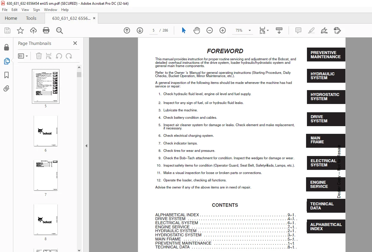
FOREWORD:
- This manual provides instruction for proper routine servicing and adjustment of the Bobcat, and
detailed overhaul instructions of the drive system, loader hydraulic/hydrostatic system and
general main frame components. - Refer to the Owner’s Manual for general operating instructions (Starting Procedure, Daily
Checks, Bucket Operation, Minor Maintenance, etc.).
A general inspection of the following items should be made whenever the machine has had
service or repair:
1. Check hydraulic fluid level, engine oil level and fuel supply.
Advise the owner if any of the above items are in need of repair.
2. Inspect for any sign of fuel, oil or hydraulic fluid leaks.
3. Lubricate the machine.
4. Check battery condition and cables.
5. Inspect air cleaner system for damage or leaks. Check element and make replacement,
if necessary.
6. Check electrical charging system.
7. Check indicator lamps.
8. Check tires for wear and pressure.
9. Check the Bob–Tach attachment for condition. Inspect the wedges for damage or wear.
10. Inspect safety items for condition (Operator Guard, Seat Belt, Safety Treads, Lamps, etc.).
11. Make a visual inspection for loose or broken parts or connections.
12. Operate the loader, checking all functions
IMAGES PREVIEW OF THE MANUAL:
Customer Support: [email protected]
PLEASE NOTE:
- This is the same manual used by the dealers to diagnose and troubleshoot your vehicle
- You will be directed to the download page as soon as the purchase is completed. The whole payment and downloading process will take anywhere between 2-5 minutes
- Need any other service / repair / parts manual, please feel free to contact [email protected] . We still have 50,000 manuals unlisted
S.V