Bobcat 730 731 732 Loader Service Manual 6556583 (6-12) – PDF DOWNLOAD
$28.95
Bobcat 730 731 732 Loader Service Manual 6556583 (6-12) – PDF DOWNLOAD
Description
Bobcat 730 731 732 Loader Service Manual 6556583 (6-12) – PDF DOWNLOAD
FILE DETAILS:
Bobcat 730 731 732 Loader Service Manual 6556583 (6-12) – PDF DOWNLOAD
Language : English
Pages : 302
Downloadable : Yes
File Type : PDF
TABLE OF CONTENTS:
Bobcat 730 731 732 Loader Service Manual 6556583 (6-12) – PDF DOWNLOAD
MAINTENANCE SAFETY 3
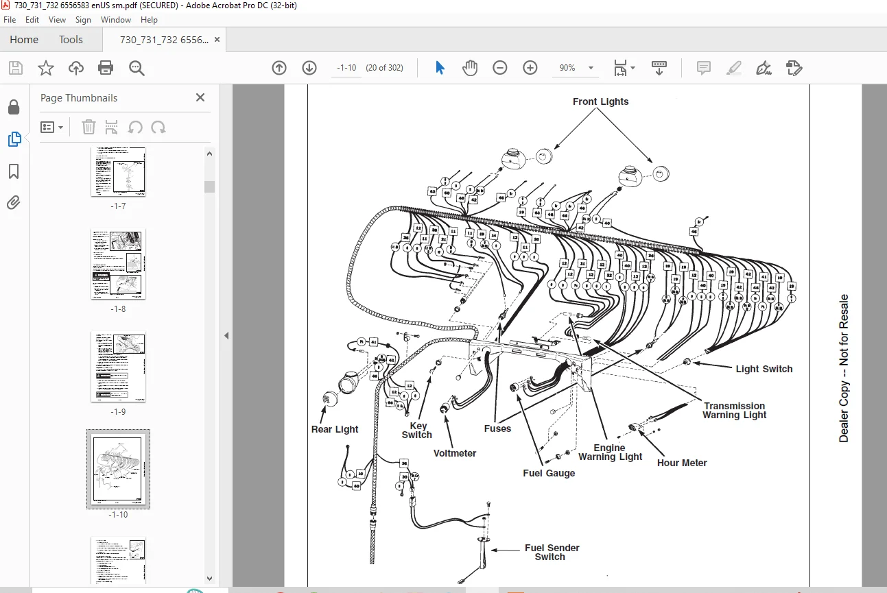
CONTENTS 5
FOREWORD 7
PREVENTIVE MAINTENANCE 9
INTRODUCTION 11
Symbols 11
Serial Number Identification 11
Loader Serial Number 11
Engine Serial Number 11
Pre–Delivery Inspection 12
30 Hour Inspection 12
SERVICE SCHEDULE 13
ENGINE SERVICE (General) 14
Engine Oil And Filter 14
Checking Oil 15
Adding Oil 15
Replacement Oil And Filter 15
Crankcase Breather 16
Air Cleaner System 16
Fuel System (730, 732) 16
Fuel Filter (Inline) 17
Fuel System (731) 17
Fuel Pump 17
Carburetor 17
732 Carburetor Adjustment 18
Idle Adjusting Needle 18
Throttle Idle Adjustment 18
Engine Cooling System 18
Removing Coolant From System (732) 18
Engine Electrical System (730, 731 & 732) 19
ROPS Electrical System 20
Installing New Battery 21
Ignition System (730 & 732) 21
Making Adjustment Of Spark Plug Gap 21
Making Adjustment Of Point Gap 21
HYDRAULIC FLUID AND FILTER 21
Fluid 21
Filter 22
TRANSMISSION AND DRIVE SYSTEM 22
Drive Chains 22
Brakes 22
Fluid 22
TIRES 22
Tire Rotation 23
LOADER LUBRICATION 23
BOB–TACH AND PIVOT PINS 23
THE ENGINE MUFFLER 24
HYDRAULIC SYSTEM 25
HYDRAULIC/HYDROSTATIC SCHEMATICS 27
TROUBLESHOOTING 37
HYDRAULIC SYSTEM INFORMATION 38
37° Flare Connections 38
Straight Thread O–Ring Fitting 38
Tubelines And Hoses 38
HYDRAULIC CONTROL VALVE 39
Relief Valve 39
Removal Of The Control Valve 40
Disassembly Of The Control Valve 41
Inlet Section 42
Tilt Section 43
Lift Section 45
Lift Section 48
Adjusting The Auxiliary Detent 50
HYDRAULIC PUMP 51
Checking Output Of The Hydraulic Pump 51
Removing The Hydraulic Pump 52
Disassembly Of The Hydraulic Pump 54
Removing And Checking The Pump Shaft 54
Installing The Hydraulic Pump 54
Starting Procedure For The Hydraulic Pump 55
LIFT CYLINDERS 55
Checking The Lift Cylinders 55
Removing The Lift Cylinder 56
Disassembly Of The Cylinders 57
Assembly Of The Cylinder 58
Installation Of The Lift Cylinder(s) 60
TILT CYLINDER 61
Checking The Tilt Cylinder 61
Removing The Tilt Cylinder 61
Disassembly Of The Tilt Cylinder (Cessna) 62
Assembly Of The Tilt Cylinder 64
Installation Of The Tilt Cylinder 67
HYDRAULIC/HYDROSTATIC RESERVOIR 67
Removing The Hydraulic/Hydrostatic Reservoir 67
Installing The Hydraulic/Hydrostatic Reservoir 67
OIL COOLER 68
Removing The Oil Cooler On The 730, 731) 68
Removing The Oil Cooler From The 732 68
Installing The Oil Cooler 68
MICRON FILTER BY–PASS VALVE 69
Removing By–Pass Valve 69
Installation Of The By–Pass Valve 69
CONTROL PEDAL 69
Removing Hydraulic Control Pedal 69
Installing The Hydraulic Control Pedal 70
Adjusting the HydraulicControl Pedal 70
HYDROSTATIC SYSTEM 71
HYDROSTATIC CIRCUIT 73
HYDROSTATIC TROUBLESHOOTING 73
STEERING LINKAGE ADJUSTMENT 76
REPLENISHING VALVES 77
Checking Replenishing Valves 77
BY–PASS VALVE 78
PUMP ASSEMBLY–REMOVAL AND INSTALLATION 78
HYDROSTATIC PUMP ASSEMBLY – REPAIR 79
Hydrostatic Pump Disassembly 79
Hydrostatic Pump Inspection 80
Yoke, Pintle Bearing, etc –Assembly to Housing 81
#2 Pump Assembly 83
#1 Pump Assembly 84
REMOVING AND INSTALLING HYDROSTATIC MOTORS 86
Removing 86
Installing 86
HYDROSTATIC MOTOR REPAIR 86
Disassembly 86
Inspection 88
Assembly 88
Timing Of The Motor 88
Initial Running Of The Motor 90
TOW VALVES 90
Installing Tow Valve 90
DRIVE SYSTEM 91
PARKING BRAKE 93
Adjustment 93
Removal And Installation 94
Block And Pucks 95
AXLES, SEALS AND BEARINGS 97
Removal 97
Installation 98
FINAL DRIVE CHAIN 102
Removal And Installation 102
REDUCTION GEARCASE 104
Removal And Installation 104
Checking Reduction Gearcase 105
Disassembly And Assembly 105
Reduction Gearcase Seal 110
Installation 111
CHAINCASE FLUID 112
Replacing Chaincase Fluid 112
MAIN FRAME 113
ROPS REMOVAL AND INSTALLATION 115
PIVOT PIN REPLACEMENT 115
BOB–TACH 116
Checking Wedges 116
Bob–Tach Removal 116
Bob–Tach Installation 116
Bob–Tach Pins 116
Bob–Tach Over–Center Stop 116
Bob–Tach Frame 117
LIFT ARMS 117
ELECTRICAL SYSTEM 119
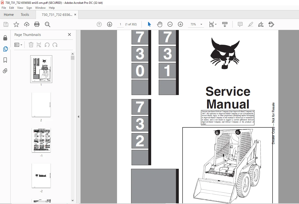
ROPS ELECTRICAL SYSTEM 121
Wiring Diagram (ROPS Electrical Circuit) S/N 12999 & Below 123
Wiring Diagram (ROPS Electrical Circuit) S/N 13000 & Above 124
GENERAL INFORMATION 125
Troubleshooting The Flywheel Alternator (730) 125
Engine Electrical (730) S/N 12999 & Below 125
Engine Wiring Diagram (730) S/N 12999 & Below 126
Troubleshooting 127
To Check the Regulator Module 128
ELECTRICAL CIRCUIT (731, 732 128
Electrical Troubleshooting 128
Engine Electrical System (731) S/N 5006–11001 & Above 130
Engine Wiring Diagram (731) 4999–11999 & Below 131
Engine Wiring Diagram (731) 5006–11001 & Above 132
Engine Electrical System (732) S/N 11999 & Below 133
Engine Electrical System (732) S/N 12000 & Above 134
Engine Wiring Diagram (732) S/N 11999 & Below 135
Engine Wiring Diagram (732) S/N 12000 & Above 136
CHART A 137
Engine Electrical System (731) S/N 4999–11999 & Below 129
ALTERNATOR BELT ADJUSTMENT AND REPLACEMENT (731, 732) 138
Check Condition Of Battery And Cables 138
Check Wiring 138
Check Alternator Output 139
Checking Regulator 139
ALTERNATOR SERVICE 139
Alternator Removal 139
Alternator Disassembly 139
Checking Rotor 140
Checking Stator 140
Checking Diode Trio 140
Checking Rectifier 140
Alternator Assembly and Installation 141
Checking Starter 141
Removing Starter 141
Starter Disassembly 141
Starter Cleaning and Inspection 142
Brush Replacement 143
Starter Assembly 143
ENGINE SERVICE 145
730 – ENGINE SERVICE (WISCONSIN ENGINE) 147
TROUBLESHOOTING 149
ENGINE IGNITION SYSTEM 150
Distributor Maintenance 150
Timing Procedure 150
Spark Plugs 150
CARBURETOR SERVICE 151
Adjustments 151
Float Adjustment 151
Governor Adjustment 151
REMOVAL OF ENGINE 151
REMOVAL OF ACCESSORIES 152
REMOVAL OF FLYWHEEL 152
REMOVAL OF AIR HOUSING 152
REMOVAL OF CARBURETOR AND MANIFOLD 152
REMOVAL OF CYLINDER HEADS 152
REMOVAL OF GEAR COVER 152
REMOVAL OF CAMSHAFT 152
REMOVAL OF IDLER GEAR AND SHAFT 153
REMOVAL OF OIL PAN 153
REMOVAL OF OIL PUMP 153
REMOVAL OF PISTONS AND CONNECTING RODS 153
REMOVAL OF VALVES AND SEAT INSERTS 154
REMOVAL OF CYLINDER BLOCK 154
REMOVAL OF CRANKSHAFT 155
REMOVAL OF CAMSHAFT 155
REMOVAL OF VALVE TAPPETS 155
INSTALLATION OF VALVE TAPPETS 155
INSTALLATION OF CAMSHAFT 155
INSTALLATION OF CRANKSHAFT 155
Three Bearing Crankshaft 155
INSTALLATION OF CYLINDER BLOCKS 156
INSTALLATION OF PISTON RINGS 156
INSTALLATION OF VALVES AND SEAT INSERTS 156
INSTALLATON OF PISTONS AND CONNECTING RODS 156
INSTALLATION OF OIL PUMP 157
OIL PAN INSTALLATION 157
INSTALLATION OF IDLER GEAR AND SHAFT 158
INSTALLATION OF CAMSHAFT GEAR 158
INSTALLATION OF GEAR COVER 158
INSTALLATION OF CYLINDER HEAD 158
INSTALLATION OF CARBURETOR AND MANIFOLD ASSEMBLY 159
INSTALLATION OF AIR HOUSING 159
INSTALLATION OF FLYWHEEL 159
INSTALLATION OF ACCESSORIES 159
731 – ENGINE SERVICE (DEUTZ ENGINE–F2L411D) 161
TROUBLESHOOTING 163
ENGINE MOUNTS 164
FUEL SYSTEM 164
Fuel And Control Linkage Adjustment 164
Venting Air From Fuel System 165
Fuel Filters 167
Fuel Lift Pump 167
Fuel Injection Pump 168
Removal Of Injection Pump 168
Injection Pump Service 168
To Install Injection Pump 168
Adjustment Of Fuel Delivery 169
FUEL INJECTION NOZZLES 170
Removal 170
Disassembly & Repair 170
Installation 170
ENGINE SERVICE 170
ENGINE REMOVAL 170
BLOWER FAN 171
Removal 171
Installation 171
Disassembly 171
Assembly 171
CYLINDER HEAD AND VALVES 171
Removal 171
Disassembly 172
Installation of Cylinder Head 174
Repair And Assembly 172
CYLINDERS, PISTONS,CONNECTING RODS 175
Assembly 176
OIL PUMP, FILTER HOUSING AND RELIEF VALVE 176
Oil Pump Removal 176
Installation 177
Oil Pressure Relief Valve 177
Filter Housing 177
ENGINE FRONT COVER 177
Removal 177
Disassembly & Inspection 177
Assembly 178
Installation 179
GOVERNOR 179
Removal And Disassembly 179
Assembly And Installation 180
CAMSHAFT (Engine Must Be Removed) 180
Removal 180
Installation 180
Crankshaft Removal 181
Inspection 181
Assembly 181
FLYWHEEL 182
731 – ENGINE SERVICE (DEUTZ ENGINE–F2L511) 161
TROUBLESHOOTING 183
ENGINE MOUNTS 184
FUEL SYSTEM 184
Fuel System Adjustment 184
Venting Air From Fuel System 185
Fuel Filters 185
Fuel Lift Pump 186
Fuel Injection Pump 186
Removal of Injection Pump 186
Injection Pump Service 186
To Install Injection Pump 186
Checking Adjustment Of Fuel Delivery 188
FUEL INJECTION NOZZLES 189
Removal 189
Disassembly And Repair Of Injector (In Shop) 189
Installation Of Injector 189
ENGINE SERVICE 190
ENGINE REMOVAL 190
BLOWER FAN 190
Removal Of Blower Fan 190
Installation 191
Disassembly 191
Assembly 191
CYLINDER HEAD AND VALVES 191
Removal And Disassembly 191
Repair And Assembly 192
Checking Piston Crown Clearance And Installation Of Cylinder Head 194
CYLINDER, PISTONS AND CONNECTING RODS 195
Assembly 196
OIL PUMP, FILTER HOUSING AND RELIEF VALVE 197
Oil Pump Removal 197
Installation 197
Oil Pressure Relief Valve 197
ENGINE FRONT COVER 197
Removal 197
Disassembly And Inspection 198
Assembly 198
Installation 199
GOVERNOR 200
Removal And Disassembly 200
Assembly And Installation 200
CAMSHAFT (Engine Must Be Out Of Machine) 201
Removal 201
Installation 201
Crankshaft Removal 201
Inspection 202
Assembly 202
FLYWHEEL 203
ENGINE OIL COOLER 203
732 – ENGINE SERVICE (FORD ENGINE ) 205
TROUBLESHOOTING 207
CHECKS AND ADJUSTMENTS 208
Oil Pressure 208
Valve Clearance 208
Carburetor, Throttle And Governor Adjustments 210
Compression 208
Ignition System 212
Coil To Ground Voltmeter Test 212
Spark Plug Wires Resistance Test 212
Spark Plug Test 212
Distributor Tests 212
Test Connections 212
Dwell Angle Check 212
Spark Strength Tests 213
Ignition System Tests 213
Battery to Coil Voltmeter Test 213
Starting Ignition Circuit Voltmeter Test 213
Breaker Point Gap Adjustment 214
Ignition Timing 214
Timing Mark Locations 214
Initial Ignition Timing 214
CARBURETOR REPAIR 215
ENGINE DIAGNOSIS AND TESTING 215
Camshaft Lobe Lift 215
Crankshaft End Play 216
Flywheel Face Alignment Check 216
Camshaft End Play 216
ENGINE OVERHAUL 216
Cylinder Head 216
Valve Guides 216
Grinding Valve Seats 217
Valves 217
Grinding Valves 217
Select Fitting Of Valves 217
Camshaft Repair 217
Crankshaft 217
Reconditioning Journals 217
To Check Crankshaft or Connecting Rod Bearings With Plastigage 217
Pistons, Pins And Rings 218
To Install Pistons 218
To Install Piston Rings 218
Installing Piston Pins 219
Valve Rocker Arm And/Or Shaft Assembly 219
Push Rods 219
Cylinder Block 219
Finishing Cylinder Walls 219
Cylinder Heads 219
Cleaning 219
Inspection 219
Tappets 220
Cleaning 220
Inspection 220
Camshaft 220
Cleaning And Inspection 220
Crankshaft 220
Inspection 220
Flywheel 220
Inspection 220
Connecting Rods 220
Cleaning 220
Inspection 221
Pistons, Pins And Rings 221
Cleaning 221
Inspection 221
Main And Connecting Rod Bearings 221
Cleaning 221
Inspection 221
Cylinder Block 221
Cleaning 221
Inspection 222
OIL PUMP 222
Cleaning 222
Inspection 222
REMOVAL OF ENGINE 222
VALVE ROCKER AND ARM COVER, ROCKER ARM AND/OR SHAFT 223
Removal And Disassembly 223
Installation 223
VALVE PUSHROD 223
Installation 224
INTAKE MANIFOLD 224
Removal 224
Installation 224
CYLINDER HEAD 224
Removal 224
Installation 225
VALVE SPRING, RETAINER AND STEM SEAL (CYLINDER HEAD REMOVED) 226
Removal 226
Installation 226
WATER PUMP 227
Removal 227
Installation 227
CYLINDER FRONT COVER, TIMING CHAIN AND CRANKSHAFT SPROCKETS 227
Removal 227
Remove Timing Cover 228
Installation 228
FRONT OIL SEAL 229
Removal 229
Installation 229
TIMING CHAIN TIGHTENER 229
Removal 229
Installation 229
CAMSHAFT AND VALVE LIFTERS 229
Removal 229
Installation 230
FLYWHEEL RING GEAR 231
Removal 231
Installation 231
OIL PAN 231
Removal 231
Installation 231
OIL PUMP 232
Removal 232
Installation 232
CRANKSHAFT REAR OIL SEAL 232
Removal 232
Installation 232
MAIN BEARINGS 232
Removal 233
Installation 233
CONNECTING ROD BEARINGS 233
Removal 233
Installation 233
PISTONS AND CONNECTING RODS 233
Removal 233
Installation 234
CRANKSHAFT 235
Removal 235
Installation 235
CAMSHAFT BEARINGS 236
Removal of Camshaft 236
Installation 236
TECHNICAL DATA 237
730 – ENGINE SPECIFICATIONS (WISCONSIN) 239
ENGINE SPECIFICATIONS, 730 (Wisconsin) 241
Fuel Specifications 241
Engine Oil 241
Valve Mechanism 241
Crankshaft 242
Idler Gear 242
Connecting Rod 242
Piston, Piston Pin, Piston Rings 242
Ignition System 242
Distributor Advance Characteristics 242
Starter 242
Engine Torque Specifications 242
LOADER SPECIFICATIONS 243
OPERATIONAL & PERFORMANCE 243
Engine 243
LOADER HYDRAULICS 243
ELECTRICAL 243
DRIVE SYSTEM 243
CAPACITIES 243
TIRES 243
MACHINE WEIGHT 243
731 – ENGINE SPECIFICATIONS (DEUTZ – F2L411D) 245
ENGINE SPECIFICATIONS, 731 (Deutz–F2L–411) 247
Fuel System 247
Governor, Front Cover And Throttle 247
Cylinder Head And Valves 247
Cylinder, Piston And Connecting Rod 247
Camshaft, Crankshaft, Bearings 248
Lubrication System 248
Torque Specification (Deutz Engine F2L411D) 249
Special Tools (Deutz F2L411D) 249
LOADER SPECIFICATIONS 250
OPERATIONAL & PERFORMANCE 250
ENGINE 250
LOADER HYDRAULICS 250
ELECTRICAL 250
DRIVE SYSTEM 250
CAPACITIES 250
TIRES 250
MACHINE WEIGHT 250
731 – ENGINE SPECIFICATIONS (DEUTZ – F2L511) 245
ENGINE SPECIFICATIONS, 731 (Deutz F2L511) 251
Fuel System 251
Governor, Front Cover And Throttle 251
Cylinder Head And Valves 251
Cylinder, Piston And Connecting Rod 251
Camshaft, Crankshaft, Bearings 252
Lubrication System 252
Torque Specifications (F2L511 Deutz Engine) 253
Special Tools (F2L511 Deutz) 254
LOADER SPECIFICATIONS 255
OPERATIONAL & PERFORMANCE 255
ENGINE 255
LOADER HYDRAULICS 255
ELECTRICAL 255
DRIVE SYSTEM 255
CAPACITIES 255
TIRES 255
MACHINE WEIGHT 255
732 – ENGINE SPECIFICATIONS (FORD) 257
ENGINE SPECIFICATIONS, 732 (Ford) 259
Fuel Specifications 259
Engine Oil 259
Lubrication System 260
Cylinder Heads 260
Valve Mechanism 260
Camshaft 261
Crankshaft 261
Connecting Rod 261
Piston 261
Piston Pin 261
Piston Rings 262
Cylinder Block 262
Ignition System 262
Starter 262
Torque Specifications for Engine 263
Special Tools (Ford) 263
LOADER SPECIFICATIONS 264
OPERATIONAL & PERFORMANCE 264
ENGINE 264
LOADER HYDRAULICS 264
ELECTRICAL 264
DRIVE SYSTEM 264
CAPACITIES 264
TIRES 264
MACHINE WEIGHT 264
TECHNICAL DATA 265
LOADER TORQUE SPECIFICATIONS 267
HYDRAULIC/HYDROSTATIC TRANSMISSION FLUID 267
CONVERSIONS 268
Decimal And Millimeter Equivalents 268
U S To Metric Conversion 268
STANDARD TORQUE SPECIFICATIONS FOR BOLTS 269
ALPHABETICAL INDEX 271
SERVICE BULLETINS 275
730–001 275
730–002 277
730–003 279
730–004 281
730–005 283
730–006 285
730–007 287
730–008 289
730–009 291
730–010 293
SERVICE MANUAL REVISIONS 275
730–1 295
730–2 297
730–3 299
730-4 301
IMAGES PREVIEW OF THE MANUAL:
Customer Support: [email protected]
PLEASE NOTE:
- This is the SAME MANUAL used by the dealerships to diagnose your vehicle
- No waiting for couriers / posts as this is a PDF manual and you can download it within 2 minutes time once you make the payment.
- Your payment is all safe and the delivery of the manual is INSTANT – You will be taken to the DOWNLOAD PAGE.
- So have no hesitations whatsoever and write to us about any queries you may have : heydownloadss @gmail.com
S.V