Bobcat 773, 773 High Flow & Turbo 773 G Series Loader Service Manual 6900834 (6-12) – PDF DOWNLOAD
$33.95
Bobcat 773, 773 High Flow & Turbo 773 G Series Loader Service Manual 6900834 (6-12) – PDF DOWNLOAD
(S/N 517611001 & Above)
(S/N 518011001 & Above)
(S/N 518111001 & Above)
(S/N 519011001 & Above)
(S/N 519211001 & Above)
(S/N 500 K 11001 & Above)
Description
Bobcat 773, 773 High Flow & Turbo 773 G Series Loader Service Manual 6900834 (6-12) – PDF DOWNLOAD
FILE DETAILS:
Bobcat 773, 773 High Flow & Turbo 773 G Series Loader Service Manual 6900834 (6-12) – PDF DOWNLOAD
Language : English
Pages : 840
Downloadable : Yes
File Type : PDF
TABLE OF CONTENTS:
Bobcat 773, 773 High Flow & Turbo 773 G Series Loader Service Manual 6900834 (6-12) – PDF DOWNLOAD
MAINTENANCE SAFETY 3
ALPHABETICAL INDEX 5
CONTENTS 7
FOREWORD 8
SAFETY INSTRUCTIONS 11
Fire Prevention 13
SERIAL NUMBER LOCATION 15
Loader Serial Number 15
Engine Serial Number 15
DELIVERY REPORT 15
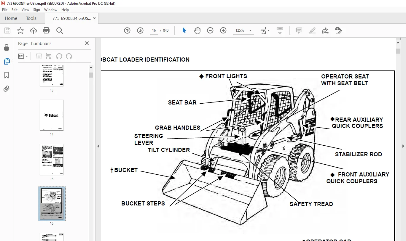
BOBCAT LOADER IDENTIFICATION 16
SAFETY AND MAINTENANCE 17
LIFTING AND BLOCKING THE LOADER 19
Procedure 19
LIFT ARM SUPPORT DEVICE 21
Installing Lift Arm Support Device 21
Removing Lift Arm Support Device 22
OPERATOR CAB 23
Description 23
Raising The Operator Cab 23
Lowering The Operator Cab 24
Emergency Exit 25
TRANSPORTING THE BOBCAT LOADER 27
Procedure 27
TOWING THE LOADER 29
Procedure 29
REMOTE START 31
Procedure 31
SERVICE SCHEDULE 35
Chart 35
AIR CLEANER SERVICE 37
Checking 37
Replacing Filter Element(s) 37
ENGINE COOLING SYSTEM 39
Cleaning The Cooling System 39
Checking The Coolant Level 40
Replacing the Coolant 40
FUEL SYSTEM 43
Fuel Specifications 43
Filling The Fuel Tank 43
Fuel Filter 44
Removing Air From The Fuel System 44
ENGINE LUBRICATION SYSTEM 45
Checking Engine Oil 45
Oil Chart 45
Replacing Oil And Filter 45
HYDRAULIC/HYDROSTATIC SYSTEM 47
Checking And Adding Fluid 47
Replacing Hydraulic/Hydrostatic Filter 47
Replacing Hydraulic Fluid 47
Breather Cap 49
FINAL DRIVE TRANSMISSION (CHAINCASE) 51
Checking And Adding Oil 51
Removing Oil From The Chaincase 51
FAN GEARBOX 53
Checking And Maintaining 53
BOB-TACH 55
Inspection And Maintenance 55
POWER BOB-TACH (OPTION) 57
Inspection And Maintenance 57
LUBRICATION OF THE BOBCAT LOADER 59
Procedure 59
TIRE MAINTENANCE 63
Wheel Nuts 63
Rotating 63
Mounting 63
SPARK ARRESTOR MUFFLER 65
Cleaning Procedure 65
HYDRAULIC SYSTEM 67
HYDRAULIC/HYDROSTATIC SCHEMATICS 73
HYDRAULIC SYSTEM INFORMATION 81
Tighten Procedures 85
Troubleshooting Chart 86
CYLINDER (LIFT) 87
Checking 87
Removal And Installation 88
Identification 90
Disassembly 91
Assembly 92
CYLINDER (TILT) 95
Checking 95
Removal And Installation 96
Rod End Pivot Pin Bushing And Seal Replacement 97
Base End Pivot Pin Replacement 97
Identification 98
Disassembly 99
Assembly 100
CYLINDER (POWER BOB-TACH) 103
Checking 103
Removal And Installation 104
Identification 105
Disassembly 106
Assembly 107
MAIN RELIEF VALVE 111
Checking 111
Adjustment 112
Removal and Installation 113
HYDRAULIC CONTROL VALVE (FOOT CONTROL) 115
Removal And Installation 115
BICS Valve Removal And Installation 118
BICS Valve, Lift Arm By-Pass Orifice Disassembly And Assembly 119
BICS Valve, Check Valve Disassembly And Assembly 120
BICS Valve Lock Valve Disassembly And Assembly 121
BICS Valve Solenoid Disassembly And Assembly 122
BICS Valve Solenoid Testing 123
Identification Chart 124
Lift Base End Restrictor 124
Load Check Valve 125
Main Relief Valve 126
Port Relief Valve 127
Anti-Cavitation Valve/Port Relief Valve 128
Anti-Cavitation Valve 128
Rubber Boot 129
Lift And Tilt Lock Block 130
Lift Spool and Detent 130
Tilt Spool Removal And Installation 139
Auxiliary Spool Removal And Installation 141
Auxiliary Electric Solenoid Disassembly 142
Port-Auxiliary Section Disassembly 143
Cleaning And Inspection 144
HYDRAULIC CONTROL VALVE (ADVANCED CONTROL SYSTEM) (ACS) 145
Description 145
Removal and Installation 145
BICS Valve Removal And Installation 149
BICS Valve, Lift Arm By-Pass Orifice Removal And Installation 151
BICS Valve, Check Valve Removal And Installation 151
BICS Valve Lock Valve Removal And Installation 153
BICS Valve Solenoid Removal And Installation 154
BICS Valve Solenoid Testing 155
Actuator Removal And Installation 156
Identification Chart (ACS) 157
Lift Base End Restrictor 158
Load Check Valve 158
Main Relief Valve 159
Port Relief Valve 160
Anti-Cavitation Valve/Port Relief Valve 161
Anti-Cavitation Valve 162
Lift Spool Removal And Installation 162
Tilt Spool Removal And Installation 163
Lift and Tilt Spool Disassembly And Assembly 164
Auxiliary Spool Removal And Installation 165
Auxiliary Electric Solenoid 166
Port-Auxiliary Section 167
Cleaning And Inspection 168
LIFT ARM BY-PASS CONTROL VALVE 169
Inspecting 169
Additional Inspection For Loaders With Advanced Hand Controls 169
Removal And Installation 169
Disassembly And Assembly 170
HYDRAULIC PUMP (ALUMINUM) 171
Checking The Output Of The Hydraulic Pump Without Power Bob-Tach 171
Checking The Output Of The Hydraulic Pump With Power Bob-Tach 173
Removal And Installation 175
Parts Identification 176
Disassembly 177
Inspection 180
Assembly 181
HYDRAULIC PUMP (ALUMINUM) (HI FLOW) 183
Checking The Output Of The High Flow Pump 183
Removal And Installation 184
Parts Identification 185
Disassembly And Assembly 186
Inspection 189
Assembly 190
HYDRAULIC PUMP (CAST IRON) 195
Check The Output Of The Hydraulic Pump Without Power Bob-Tach 195
Check The Output Of The Hydraulic Pump With Power Bob-Tach 197
Removal And Installation 199
Identification 201
Disassembly And Assembly 202
HYDRAULIC PUMP (CAST IRON) (HI FLOW) 207
Check The Output Of The High Flow Pump 207
Removal And Installation 209
Identification 211
Disassembly And Assembly 212
HYDRAULIC FILTER HOUSING 221
Removal And Installation 221
HYDRAULIC FLUID RESERVOIR 223
Fluid Removal 223
Removal And Installation (Early Style) 223
Removal And Installation (Later Style) 226
BUCKET POSITION VALVE 229
Solenoid Removal And Installation 229
Solenoid Testing 229
Removal and Installation 230
Disassembly And Assembly 232
SELECT VALVE 235
Checking The High Flow Pump Relief Valve 235
Removal and Installation 237
Disassembly And Assembly 240
Solenoid Testing 245
REAR AUXILIARY DIVERTER VALVE (SINGLE SHUTTLE) 247
Removal And Installation 247
Disassembly and Assembly 249
Inspection 250
Solenoid Testing 250
REAR AUXILIARY DIVERTER VALVE (DUAL SHUTTLE) 251
Removal And Installation 251
Disassembly And Assembly 253
Inspection 256
Solenoid Testing 256
POWER BOB-TACH BLOCK (ALUMINUM GEAR PUMP) 257
Removal And Installation 257
Disassembly And Assembly 258
POWER BOB-TACH BLOCK (CAST IRON GEAR PUMP) 265
Removal And Installation 265
Disassembly And Assembly 267
FRONT AUXILIARY PRESSURE RELIEF BLOCK 275
Removal And Installation 275
Disassembly And Assembly 276
Front Auxiliary Pressure Relief Block Inspection 277
Solenoid Testing 277
FRONT AUXILIARY HYDRAULIC COUPLER BLOCK 279
Removal and Installation 279
Disassembly And Assembly 279
HYDROSTATIC SYSTEM 281
HYDROSTATIC SYSTEM INFORMATION 283
Troubleshooting Chart 283
Replenishing Valve Function 284
HYDROSTATIC MOTOR 285
Removal And Installation 285
Parts Identification 287
Disassembly 288
Assembly 293
Carrier Shaft Seal Replacement 299
Carrier Removal And Installation 301
Carrier Parts Identification 303
Carrier Disassembly 304
Carrier Assembly 305
CHARGE PRESSURE 309
Sender Removal And Installation 309
Checking Charge Pressure 309
Adjusting 310
HYDROSTATIC PUMP 311
Replenishing/High Pressure Relief Valve 311
Removal And Installation 312
Parts Identification (Right Half) 314
Parts Identification (Left Half) 316
Hydraulic Pump Removal And Installation 318
Pump Separation 318
Disassembly 319
Assembly 325
DRIVE BELT 333
Shield Removal And Installation 333
Drive Belt Adjusting 333
Drive Belt Replacement 334
Tensioner Pulley Removal And Installation 336
Tensioner Pulley Parts Identification 337
Tensioner Pulley Disassembly 338
Tensioner Pulley Assembly 339
OIL COOLER 341
Removal and Installation 341
DRIVE SYSTEM 343
BRAKE 345
Pedal Removal And Installation 345
Pedal Disassembly And Assembly 346
Switch Operated Parking Brake 346
Disk Removal And Installation 347
DRIVE COMPONENTS 349
Axle Seal Removal And Installation 349
Axle Sprocket And Bearings Removal And Installation 351
Chain Removal And Installation 356
CHAINCASE 359
Checking And Adding Oil 359
Removing The Oil 359
Front Cover Removal And Installation 360
Center Cover Removal And Installation 361
Rear Cover Removal And Installation 362
MAIN FRAME 363
SEAT BAR 367
Removal And Installation 367
Assembling Components 369
Compression Spring Disassembly And Assembly 371
OPERATOR CAB 373
Gas Cylinder Removal And Installation 373
Gas Cylinder Disassembly 375
Removal And Installation 376
OPERATOR SEAT 379
Removal And Installation 379
Seat Belt Removal And Installation 379
OPERATOR SEAT (SUSPENSION) 381
Removal And Installation 381
Seat Belt Inspection (Suspension) 381
Slide Rail Removal And Installation 382
Cushion Removal And Installation 382
Back Removal And Installation 383
Shock Removal And Installation 384
3-Point Seat Belt Removal And Installation 385
BOB-TACH 387
Removal And Installation 387
Bob-Tach Lever And Wedge 388
Pivot Pin Bushing And Seal Replacement 389
POWER BOB-TACH 391
Removal And Installation 391
Power Bob-Tach Lever And Wedge 392
Pivot Pin Bushing And Seal Replacement 394
LIFT ARM 395
Removal And Installation 395
Link Removal And Installation 399
Stabilizer Bar Removal And Installation 400
REAR GRILL 401
Gas Cylinder Removal And Installation 401
Removal And Installation 402
REAR DOOR 403
Removal And Installation 403
Striker Removal and Installation 404
Striker Disassembly and Assembly 404
Door Latch and Catch Adjustment 405
Latch Removal and Installation (Early Style) 406
Latch Removal and Installation (Later Style) 406
FUEL TANK 407
Removal And Installation 407
Fuel Level Sender 408
Fuel Fill Screen 408
CONTROL PEDALS 411
Removal And Installation 411
Pedal Adjustment 411
Crossbar Linkage Removal and Installation 412
Lift Foot Pedal Linkage Removal and Installation 413
Tilt Foot Pedal Linkage Removal and Installation 413
CONTROL PEDALS (ACS) 415
Foot Sensor Removal And Installation 415
Foot Pedal Removal And Installation 416
Foot Pedal Linkage Disassembly And Assembly 417
CONTROL PANEL 419
Removal and Installation 419
Shock Removal And Installation 421
Shaft Removal And Installation 421
Shaft Disassembly And Assembly 421
Linkage Removal And Installation 422
Linkage Adjustment 425
Linkage Neutral Adjustment 428
CONTROL HANDLE 431
Control Lever Removal And Installation 431
Control Lever Boot 431
CONTROL HANDLE (ADVANCED HAND CONTROL) (AHC) 433
Components Identification 433
Handle Control Unit Removal And Installation 433
Control Handle Removal and Installation 435
Control Handle Disassembly and Assembly 435
Control Lever Removal and Installation 436
Control Lever Boot 437
CONTROL HANDLE (ADVANCED HAND CONTROL) (AHC) W/PUSH BUTTON FLOAT 439
Components Identification 439
Handle Sensor Removal And Installation 440
Control Handle Removal and Installation 442
Control Handle Disassembly and Assembly 443
Control Lever Removal and Installation 444
Control Lever Boot 445
CONTROL HANDLE (ADVANCED CONTROL SYSTEM) (ACS) ADVANCED HAND CONTROL 447
Components Identification 447
Handle Sensor Removal And Installation 447
Control Handle Removal and Installation 450
Control Handle Disassembly and Assembly 451
Control Lever Removal and Installation 452
Control Lever Boot 453
CONTROL HANDLE (ADVANCED CONTROL SYSTEM) (ACS) SELECTABLE HAND/FOOT CONTROL 455
Components Identification 455
Handle Sensor Removal And Installation 456
Control Handle Removal and Installation 459
Control Handle Disassembly and Assembly 460
Control Lever Removal and Installation 460
Control Lever Boot 461
ELECTRICAL SYSTEM 463
ELECTRICAL SCHEMATICS 467
ELECTRICAL SYSTEM INFORMATION 477
Troubleshooting Chart 479
Description 480
Fuse Location 481
Relay Switch Location 481
Solenoid Test 482
BATTERY 483
Removal And Installation 483
Servicing 484
Using A Booster Battery (Jump Starting) 485
ALTERNATOR (55 AMP) 487
Adjusting The Alternator Belt 487
Alternator Output Test 487
Rectifier (Diode) Test 488
Alternator Regulator Test 488
Removal And Installation 490
Disassembly 491
Stator Continuity Test 491
Stator Ground Test 491
Rotor Continuity Test 492
Rotor Ground Test 492
Rectifier Continuity (Diode) Test 492
Assembly 493
ALTERNATOR (90 AMP) 495
Adjusting The Alternator Belt 495
Alternator Identification 495
Charging System Check 496
Alternator Voltage Test 497
Low Voltage Test 497
High Voltage Test 498
Removal And Installation 498
Rectifier Continuity (Diode) Test 499
Alternator Regulator Test 500
Disassembly 501
Stator Continuity Test 501
Stator Ground Test 501
Rotor Continuity Test 502
Rotor Ground Test 502
Assembly 502
STARTER (NIPPONDENSO) 503
Checking 503
Removal And Installation 503
Parts Identification 505
Disassembly 506
Inspection And Repair 511
No Load Test 514
Assembly 515
STARTER (VALEO) 521
Checking 521
Removal And Installation 522
Parts Identification 523
Disassembly and Assembly 524
Inspection And Repair 526
No Load Test 529
INSTRUMENT PANEL 531
Left Panel 531
Right Panel – (Standard) (With Key Switch) 532
Right Panel – (Deluxe) (With Keyless Start) 533
Right Panel Setup Display Options (Deluxe) 535
Passwords 536
Changing the Password 536
Option and Field Accessory Panels 538
Removal And Installation 539
Front Accessory Panel Removal And Installation 540
LIGHTS 541
Front Removal And Installation 541
Rear Removal And Installation 542
BOBCAT CONTROLLER 543
Identification Chart 543
Removal And Installation 544
DIAGNOSTICS 545
Service Codes 545
BICS™ SYSTEM 551
Inspecting The BICS™ Controller (Engine STOPPED – Key ON) 551
Inspecting Deactivation Of The Auxiliary Hydraulics System (Engine STOPPED – Key ON) 551
Inspecting The Seat Bar Sensor (Engine RUNNING) 551
Inspecting The Traction Lock (Engine RUNNING) 551
Inspecting The Lift Arm By-Pass Control 552
Additional Inspection For Loaders With Advanced Hand Controls (AHC) 552
Troubleshooting Chart 553
Troubleshooting Guide 554
SEAT BAR SENSOR 555
Troubleshooting Chart 555
Test 556
Removal And Installation 557
BICS™ Circuit Test 558
TRACTION LOCK 559
Troubleshooting Chart 559
Inspecting 560
Solenoid Removal And Installation 560
Guide Removal 562
Guide Installation 564
ADVANCE HAND CONTROL (AHC) SYSTEM 567
Components Identification 567
Troubleshooting Guide 568
Parts Identification 569
AHC Controller Removal And Installation 570
Handle Control Unit Connector 570
Switch Handle Removal and Installation 571
Actuators Disassembly and Assembly 574
ADVANCED HAND CONTROL (AHC) SYSTEM (W/ PUSH BUTTON FLOAT) 577
Components Identification 577
Troubleshooting Guide 578
Controller Connector And Wire Identification 579
AHC Controller Removal And Installation 580
Handle Sensor Removal And Installation 580
Handle Sensor Connector 582
Switch Handle Removal and Installation 583
Actuators Disassembly and Assembly 586
ADVANCED CONTROL SYSTEM (ACS) ADVANCED HAND CONTROL 589
Components Identification 589
Troubleshooting Guide 590
Controller, Connector And Wire Identification 591
ACS Controller Removal And Installation 592
Handle Sensor Connector 592
Switch Handle Removal 593
Switch Handle Installation 595
Actuators Disassembly And Assembly 598
ADVANCED CONTROL SYSTEM (ACS) SELECTABLE HAND/FOOT CONTROL 599
Components Identification 599
Troubleshooting Guide 601
Controller, Connector And Wire Identification 602
ACS Controller Removal And Installation 603
Handle Sensor Connector 603
Switch Handle Removal 604
Switch Handle Installation 606
Actuators Disassembly And Assembly 609
Handle Lock Solenoid Removal And Installation 610
Handle Lock Solenoid Disassembly And Assembly 610
Handle Lock Solenoid Connector 611
Calibration Procedure 612
Foot Sensor Disassembly And Assembly 615
Foot Sensor Connector 616
Foot Lock Solenoid Removal And Installation 617
Foot Lock Solenoid Connector 617
ELECTRICAL/HYDRAULIC CONTROLS REFERENCE 619
Controls Identification Chart 619
ENGINE SERVICE 621
TROUBLESHOOTING 623
Chart 623
ENGINE SPEED CONTROL 625
Removal And Installation 625
Disassembly 625
MUFFLER 627
Removal And Installation 627
AIR CLEANER 629
Removal And Installation (Non Turbo) 629
Removal And Installation ( Turbo) 630
RADIATOR 631
Removal And Installation 631
COOLING FAN 633
Drive Tension Pulley Removal And Installation 633
Gearbox/Blower Housing Removal And Installation 634
Blower Housing Grill Removal And Installation 636
Blower Disassembly And Assembly 636
Gearbox Parts Identification 638
Gearbox Disassembly 639
Gearbox Assembly 643
Gearbox Checking Backlash 648
ENGINE COMPONENTS AND TESTING 651
Compression Checking 651
Glow Plugs Checking 652
Glow Plugs Removal And Installation 652
Fuel Shut-Off Solenoid, Checking 653
Fuel Shut-Off Solenoid, Adjusting 653
Fuel Shut-Off Solenoid Removal And Installation 654
Checking 654
Fuel Injection Pump Removal And Installation 655
Timing The Injection Pump 658
Fuel Injector Removal And Installation 660
Fuel Injector Checking 662
Fuel Injector Disassembly 662
Fuel Injector Assembly 663
Valve Clearance Adjustment 663
Rocker Arm And Shaft Checking 664
Valve Timing, Checking 664
ENGINE 665
Removal And Installation 665
Engine Mount Replacement 671
FLYWHEEL AND HOUSING 673
Flywheel Removal And Installation 673
Ring Gear Removal And Installation 674
Housing Removal And Installation 674
RECONDITIONING THE ENGINE-KUBOTA V2203-EB AND V2003T-EB (TURBO) 677
Cylinder Head Removal And Installation 677
Cylinder Head Disassembly And Assembly 678
Cylinder Head Servicing 679
Cylinder Head Top Clearance 679
Checking The Valve Guide 680
Reconditioning The Valve And Valve Seat 681
Valve Spring 682
Rocker Arm And Shaft Checking 683
Timing Gearcase Cover Removal And Installation 683
Idler Gear And Camshaft Removal And Installation 685
Servicing The Camshaft 686
Servicing The Idle Gear And Shaft 688
Timing Gears Checking Backlash 689
Fuel Camshaft Removal And Installation 689
Fuel Camshaft Governor 690
Crankshaft Gear Removal And Installation 690
Oil Pump Removal And Installation 691
Oil Pump Service 691
Checking Engine Oil Pressure 693
Relief Valve 693
Piston And Connecting Rod Removal And Installation 694
Servicing The Piston And Connecting Rod 695
Connecting Rod Alignment 697
Crankshaft And Bearings Removal And Installation 698
Servicing The Crankshaft And Bearings 699
Checking The Cylinder Bore 703
Water Pump Disassembly And Assembly 703
TURBOCHARGER 705
Troubleshooting 705
Description 706
Removal and Installation 706
HEATING, VENTILATION, AIR CONDITIONING 709
AIR CONDITIONING SYSTEM FLOW 712
Principals 712
Chart 713
COMPONENTS 715
Identification 715
SAFETY 719
Safety Equipment 719
REGULAR MAINTENANCE 721
Filter Elements Removal And Installation 721
Compressor Drive Belt Inspection 722
Cleaning The Condenser 722
BASIC TROUBLESHOOTING 725
Poor A/C Performance 725
Cleaning The A/C Evaporator Coil & Heater Coil 725
Compressor Drive Belt Inspection: 728
Checking The Electrical System 728
Engine Coolant By-Passing The Heater Valve 736
Heater Valve Not Opening Or Closing 737
GENERAL AIR CONDITIONING SERVICE GUIDELINES 739
Compressor Oil 739
Compressor Oil Check 740
Component Replacement And Refrigeration Leaks 741
SYSTEM TROUBLESHOOTING CHART 743
Gauge Pressure Related Troubleshooting 744
TEMPERATURE/PRESSURE 747
Chart 747
AIR CONDITIONING SERVICE 749
Chart 749
SYSTEM CHARGING AND RECLAMATION 751
Reclamation Procedure 751
Charging Procedure With A Manifold Gauge Set 754
Charging Procedure 755
COMPRESSOR 757
Removal And Installation 757
Compressor Clutch Disassembly 758
CONDENSER 763
Removal And Installation 763
RECEIVER/DRIER 765
Removal And Installation 765
PRESSURE RELIEF VALVE 767
Removal And Installation 767
PRESSURE SWITCH 769
Removal And Installation 769
EVAPORATOR/HEATER UNIT 771
Removal And Installation 771
Disassembly And Assembly 773
THERMOSTAT 775
Removal And Installation 775
EXPANSION VALVE 777
Removal And Installation 777
EVAPORATOR 779
Removal And Installation 779
HEATER COIL 781
Removal And Installation With A/C 781
Removal And Installation Without A/C 782
HEATER/AC FAN 783
Removal And Installation 783
Disassembly And Assembly 784
Wire Connector Removal and Installation 786
HEATER VALVE 789
Removal and Installation 789
Disassembly And Assembly 789
SPECIFICATIONS 793
LOADER SPECIFICATIONS (773) 795
Loader Dimensions 795
Performance 796
Controls 796
Engine 796
Hydraulic System 797
Electrical 798
Drive System 798
Capacities 798
Tires 799
ENGINE SPECIFICATIONS – KUBOTA V2203-EB 801
Fuel Injection Nozzles 801
Fuel Injection Pump 801
Cylinder Head 801
Valves 801
Valve Springs 802
Valve Timing 802
Rocker Arms 802
Camshaft 802
Tappet 802
Cylinders 803
Piston Rings 803
Pistons 803
Connecting Rod 803
Oil Pump 803
Crankshaft 804
Timing Gear 804
Thermostat 804
Crankshaft Re-Grind Data 805
ENGINE SPECIFICATIONS – KUBOTA V2003T-EB (TURBO) 807
Fuel Injection Nozzles 807
Fuel Injection Pump 807
Cylinder Head 807
Valves 807
Valve Springs 808
Valve Timing 808
Rocker Arms 808
Camshaft 808
Tappet 808
Cylinder Liner 809
Piston Rings 809
Pistons 809
Connecting Rod 809
Oil Pump 809
Crankshaft 810
Timing Gear 810
Thermostat 810
Crankshaft Re-Grind Data 811
TORQUE SPECIFICATIONS FOR BOLTS 813
Torque For General SAE Bolts 813
Torque For General Metric Bolts 814
HYDRAULIC CONNECTION SPECIFICATIONS 815
O-ring Face Seal Connection 815
Straight Thread O-ring Fitting 815
Tubelines And Hoses 815
Flare Fitting 816
O-ring Flare Fitting 817
Port Seal Fitting 819
HYDRAULIC/HYDROSTATIC FLUID SPECIFICATIONS 821
Specifications 821
SMR 825
Revision No: 773/773H-1 825
Revision No: 773/773H-2 827
Revision No: 773/773H-3 829
Revision No: 773/773H-4 831
Revision No: 773/773H-5 833
Revision No: 773-6 835
Revision No: 773-7 837
DESCRIPTION:
Bobcat 773, 773 High Flow & Turbo 773 G Series Loader Service Manual 6900834 (6-12) – PDF DOWNLOAD
(S/N 517611001 & Above)
(S/N 518011001 & Above)
(S/N 518111001 & Above)
(S/N 519011001 & Above)
(S/N 519211001 & Above)
(S/N 500 K 11001 & Above)
FOREWORD:
This manual is for the Bobcat loader mechanic. It provides necessary servicing and adjustment
procedures for the Bobcat loader and its component parts and systems. Refer to the Operation &
Maintenance Manual for operating instructions, Starting procedure, daily checks, etc.
SAFETY INSTRUCTIONS:
The following publications provide information on the safe use and maintenance of the Bobcat machine and attachments:
Customer Support: [email protected]
IMAGES PREVIEW OF THE MANUAL:
PLEASE NOTE:
- This is the SAME MANUAL used by the dealerships to diagnose your vehicle
- No waiting for couriers / posts as this is a PDF manual and you can download it within 2 minutes time once you make the payment.
- Your payment is all safe and the delivery of the manual is INSTANT – You will be taken to the DOWNLOAD PAGE.
- So have no hesitations whatsoever and write to us about any queries you may have : heydownloadss @gmail.com
S.V