BOBCAT 7753 Skid Steer Loader Service Repair Manual – PDF DOWNLOAD
Original price was: $35.95.$28.95Current price is: $28.95.
BOBCAT 7753 Skid Steer Loader Service Repair Manual
Description
BOBCAT 7753 Skid Steer Loader Service Repair Manual
FILE DETAILS:
LANGUAGE:ENGLISH
PAGES:315
DOWNLOADABLE:YES
FILE TYPE:PDF
BOBCAT 7753 SKID STEER LOADER SERVICE REPAIR MANUAL – PDF DOWNLOAD:
IMAGES PREVIEW OF THE MANUAL:
DESCRIPTION:
BOBCAT 7753 Skid Steer Loader Service Repair Manual
FOREWORD:
This manual is for the Bobcat loader mechanic. It provides necessary servicing and adjustment procedures for the Bobcat loader and its component parts and systems. Refer to the Operation &
Maintenance Manual for operating instructions, starting procedure, daily checks, etc.
SAFETY INSTRUCTIONS:
Wear tight fitting clothing and any other required safety apparel when operating or servicing the loader.
• Wear safety glasses when maintaining or servicing the loader.
• Exhaust gases can kill, vent engine exhaust outdoors.
• Know where fire extinguisher and first aid kits are located and how to use them.
• Do not run the Bobcat loader where exhaust, arcs, sparks or hot components can contact flammable material, explosive dust or gases.
• Check fuel and hydraulic tubes, hoses and fittings for damage and leakage. Never use open flame or bare skin to check for leaks. Tighten or replace any parts that show leakage. Always clean fluid spills. DO NOT use gasoline or diesel fuel for cleaning parts. Use commercial nonflammable solvents.
• Clean the loader before doing any welding. Cover rubber hoses, battery and all other flammable parts. Keep a fire extinguisher near the loader when welding.
• Have good ventilation when welding or grinding painted parts. Wear dust mask when grinding painted parts. Toxic dust and gas can be produced.
• Stop the engine and let it cool before adding fuel. No smoking!
• Use the procedure in this Manual for connecting battery.
• Use the procedure in this Manual for cleaning the spark arrestor muffler after each 100 hours of operation.
TABLE OF CONTENTS:
BOBCAT 7753 Skid Steer Loader Service Repair Manual
AIR CLEANER SERVICE
Optional 1–7
Replacing Filter Element1–7
Standard 1–7
ALTERNATOR BELT
Adjusting The Alternator Belt1–15
BATTERY
Removal And Installation1–16
COOLING SYSTEM
Checking The Coolant Level 1–13
Cleaning The Coolant System 1–13
Removing Coolant From The Cooling System 1–14
DIAGNOSTIC TOOL
Procedure 1–31
DRIVE BELT
Adjustment1–23
Adjusting The Drive Belt With Spring Loaded Drive Idler 1–25
Drive Belt Replacement 1–24
Replacing The Drive Belt With Spring Loaded Drive Idler1–26
ENGINE COOLING SYSTEM
Cleaning The Cooling System 1–13
Coolant Level 1–13
Removing Coolant From The Cooling System 1–14
ENGINE LUBRICATION SYSTEM
Checking Engine Oil 1–11
Replacing Of Oil And Filter 1–11
FAN GEARBOX
Checking Grease Level 1–22
FINAL DRIVE TRANSMISSION (CHAINCASE)
Checking And Adding Oil1–22
Removing Oil From The Chaincase 1–22
FUEL SYSTEM
Filling The Fuel Tank 1–9
Fuel Filter 1–9
Fuel Specifications 1–9
Removing Air From The Fuel System 1–10
HYDRAULIC/HYDROSTATIC SYSTEM
Checking And Adding Fluid 1–17
Replacing Hydraulic/Hydrostatic Filter 1–17
Checking The Hydraulic Reservoir Breather Cap 1–18
Replacing Hydraulic Fluid 1–19
Continued On Next Page
Revised Mar 98
–1–0–
7753 Bobcat Loader
Service Manual
PREVENTIVE MAINTENANCE (Cont’d)
Page
Number
LIFT ARM SUPPORT DEVICE
Installing The Lift Arm Support Device1–4
Removing The Lift Arm Support Device 1–4
LIFTING AND BLOCKING THE LOADER
Procedure 1–2
PIVOT PINS1–29
PREVENTIVE MAINTENANCE 1–2
LUBRICATION OF THE BOBCAT LOADER
Procedure 1–27
OPERATING SYSTEM SERVICE CODES
Chart 1–32
OPERATOR CAB
Description1–4
Emergency Exit1–6
Lowering The Operator Cab 1–5
Raising The Operator Cab 1–5
REMOTE START SWITCH
Procedure 1–30
SEAT BAR SYSTEM
Description1–6
Seat Bar Inspection1–6
Seat Bar Maintenance 1–6
SERVICE CODES
Chart 1–33
SERVICE SCHEDULE
Chart 1–1
SINGLE POINT LIFT1–3
SPARK ARRESTER MUFFLER
Cleaning Procedure1–20
TIRE MAINTENANCE
Tire Mounting 1–21
Tire Rotation 1–21
Wheel Nuts1–21
TRANSPORTING THE LOADER
Procedure 1–3
TROUBLESHOOTING THE BOSS & LCD DISPLAY
Chart 1–35
USING A BOOSTER BATTERY (JUMP STARTING)
Procedure 1–16
CONTROL PEDALS
Adjustment2–18
Removal and Installation2–18
HYDRAULIC CONTROL VALVE
Checking the Main Relief Valve 2–7
Main Relief Valve Removal and Installation2–8
Removal and Installation2–9
HYDRAULIC FILTER HOUSING
Removal and Installation2–15
HYDRAULIC FLUID RESERVOIR
Removal and Installation2–17
HYDRAULIC PUMP
Checking the Output of the Pump 2–11
Removal and Installation2–12
HYDRAULIC SYSTEM INFORMATION
Flare Connections 2–2
O–Ring Face Seal Connections 2–2
Straight Thread O–Ring Fitting 2–2
Tubelines and Hoses 2–2
LIFT CYLINDER(S)
Checking the Lift Cylinder(s) 2–3
Removal and Installation2–3
PEDAL INTERLOCK LINKAGE
Adjustment2–19
Installation2–19
TILT CYLINDER
Checking the Tilt Cylinder 2–5
Removal and Installation2–5
Rod End Seal 2–6
TROUBLESHOOTING
Chart 2–1
DRIVE BELT TENSIONER PULLEY
Assembly 3–28
Checking Pulley End Play 3–32
Disassembly 3–26
FRONT PANEL
Removal and Installation3–5
HYDROSTATIC MOTOR
Removal and Installation3–20
HYDROSTATIC PUMP
Removal and Installation3–22
HYDROSTATIC SYSTEM INFORMATION
Replenishing Valve Function 3–4
OIL COOLER
Removal and Installation3–25
SPRING LOADED DRIVE BELT IDLER
Assembly 3–37
Disassembly 3–35
Parts Identification 3–34
Removal and Installation3–33
STEERING LEVERS
Disassembly and Assembly 3–7
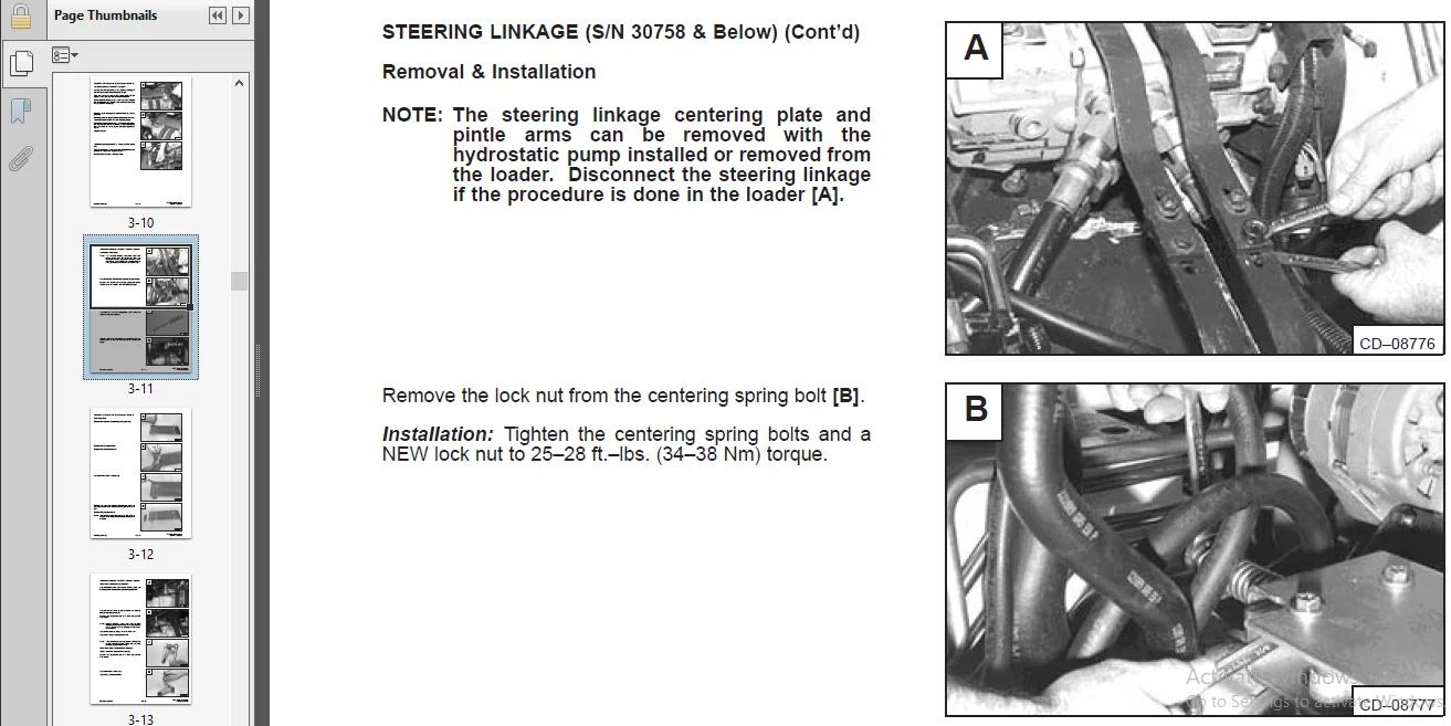
STEERING LINKAGE
Centering Plate (S/N 30758 & Below) 3–12
Pintle Arm Removal and Installation (S/N 30758 & Below) 3–13
Pintle Arm Lobe Removal and Installation (S/N 30758 & Below) 3–13
Removal and Installation (S/N 30758 & Below) 3–11
Removal and Installation (S/N 30759 & Above)3–14
Steering Linkage Adjustment (S/N 30758 & Below) 3–9
Steering Linkage Adjustment (S/N 30759 & Above) 3–16
Steering Neutral Adjustment (S/N 30759 & Above) 3–18
TROUBLESHOOTING
Chart 3–3
AXLE HUB AND SEAL
Removal and Installation4–12
AXLE SPROCKET AND BEARINGS
Removal and Installation4–15
CENTER TRANSMISSION COVER
Installation4–6
CHAINCASE FLUID
Replacing the Chaincase Fluid 4–20
DRIVE CHAIN
Removal and Installation4–19
FRONT CHAINCASE COVER
Removal and Installation4–7
MOTOR CARRIER (Later Models)
Early Models 4–9
Disassembly and Assembly 4–11
Removal and Installation4–10
Shaft Seal Replacement4–9
PARKING BRAKE
Adjustment4–1
Brake Block and Pads 4–5
Brake Disc4–6
Removal and Installation4–2
REAR CHAINCASE COVER
Removal and Installation4–8
BOB–TACH
Bob–Tach Lever and Wedge 5–9
Removal and Installation 5–7
FUEL TANK
Fuel Level Sender 5–17
Removal and Installation5–16
LIFT ARMS
Removal and Installation5–14
LIFT ARM LINK
Removal and Installation5–12
OPERATOR CAB
Disassembly and Assembly 5–3
Removal and Installation 5–1
OPERATOR CAB GAS CYLINDER
Removal and Installation 5–1
REAR DOOR
Removal and Installation 5–4
REAR GRILL
Removal and Installation 5–5
SEAT BAR
Removal and Installation 5–6
ALTERNATOR
Alternator Output Test (New Style) 6–5
Alternator Regulator Test (New Style) 6–6
Assembly (New Style) 6–13
Checking the Alternator Output (Old Style) 6–3
Checking the Alternator Regulator (Old Style)6–4
Checking the Rectifier (Old Style) 6–9
Checking the Rotor (Old Style) 6–8
Checking the Stator (Old Style)6–9
Disassembly (New Style) 6–11
Disassembly (Old Style) 6–8
Parts Identification (New Style) 6–13
Rectifier Continuity (Diode) Test (New Style) 6–12
Rectifier (Diode) Test (New Style) 6–5
Removal and Installation (Old Style)6–7
Rotor Continuity Test (New Style) 6–11
Rotor Ground Test (New Style)6–11
Stator Continuity Test (New Style) 6–11
Stator Ground Test (New Style) 6–11
BATTERY
Removal and Installation 6–2
ELECTRICAL SYSTEM INFORMATION
Description 6–1
INSTRUMENT PANEL
Removal and Installation6–21
OPERATING SYSTEM UNIT
Removal and Installation6–20
STARTER
Checking the Starter6–14
Cleaning and Inspection6–17
Disassembly and Assembly 6–15
Parts Identification 6–19
Removal and Installation6–14
TROUBLESHOOTING
Chart 6–1
AIR CLEANER
Removal and Installation7–23
BELT SHIELD
Removal and Installation7–32
BLOWER HOUSING/FAN GEARBOX
Removal and Installation 7–5
Tension Pulley 7–7
CRANKSHAFT AND BEARINGS
Removal and Installation7–62
Servicing the Crankshaft and Bearings7–63
CRANKSHAFT GEAR
Removal and Installation7–56
CYLINDER BORE
Checking the Cylinder Bore 7–67
CYLINDER HEAD
Disassembly and Assembly 7–44
Removal and Installation7–43
Servicing the Cylinder Head 7–45
Top Clearance 7–45
ENGINE
Engine Mounts Removal and Installation 7–29
Removal and Installation7–24
ENGINE COMPRESSION
Checking 7–34
ENGINE MUFFLER
Removal and Installation 7–4
FAN GEAR BOX
Assembly 7–13
Long Housing 7–13
Short Housing7–15
Checking Backlash 7–18
Disassembly 7–8
Long Housing 7–8
Short Housing7–10
Parts Identification 7–21
FLYWHEEL
Flywheel Ring Gear7–31
Removal and Installation7–31
FUEL CAMSHAFT
Governor 7–55
Removal and Installation7–55
Revised Apr 94
ENGINE
SERVICE
–7–0–
7753 Bobcat Loader
Service Manual
ENGINE SERVICE
Page
Number
FUEL INJECTION PUMP
Adjusting Shut–Off Linkage 7–36
Checking the Injection Pump7–36
Removal and Installation7–37
Timing the Injection Pump 7–39
FUEL INJECTOR NOZZLES 7–40
Checking the Injector Nozzle7–42
Removal and Installation7–40
GLOW PLUGS
Checking 7–35
Removal and Installation7–25
IDLER GEAR AND CAMSHAFT
Removal and Installation7–52
Servicing the Camshaft 7–53
Servicing the Idler Gear and Shaft7–54
OIL PUMP
Checking Engine Oil Pressure 7–57
Oil Pump Service 7–56
Removal and Installation7–56
Relief Valve 7–57
PISTON AND CONNECTING ROD
Connecting Rod Alignment 7–61
Removal and Installation7–58
Servicing the Piston and Connecting Rod 7–59
RADIATOR
Removal and Installation 7–2
ROCKER ARM AND SHAFT
Checking 7–49
TENSION PULLEY
Removal and Installation7–22
TIMING GEARS
Checking Backlash 7–54
TIMING GEARCASE COVER
Removal and Installation7–50
TROUBLESHOOTING
Chart 7–1
VALVE CLEARANCE
Adjustment7–33
VALVES, VALVE SEAT AND GUIDE
Checking the Valve Guide 7–46
Reconditioning the Valve and Valve Seat 7–47
Valve Spring 7–48
WATER PUMP
Disassembly and Assembly 7–68
PLEASE NOTE:
- This is the SAME exact manual used by your dealers to fix your vehicle.
- The same can be yours in the next 2-3 mins as you will be directed to the download page immediately after paying for the manual.
- Any queries / doubts regarding your purchase, please feel free to contact [email protected]