Bobcat 825 Loader Service Manual 6549899 (6-12) – PDF DOWNLOAD
$27.95
Bobcat 825 Loader Service Manual 6549899 (6-12) – PDF DOWNLOAD
Description
Bobcat 825 Loader Service Manual 6549899 (6-12) – PDF DOWNLOAD
FILE DETAILS:
Bobcat 825 Loader Service Manual 6549899 (6-12) – PDF DOWNLOAD
Language : English
Pages : 178
Downloadable : Yes
File Type : PDF
TABLE OF CONTENTS:
Bobcat 825 Loader Service Manual 6549899 (6-12) – PDF DOWNLOAD
MAINTENANCE SAFETY 3
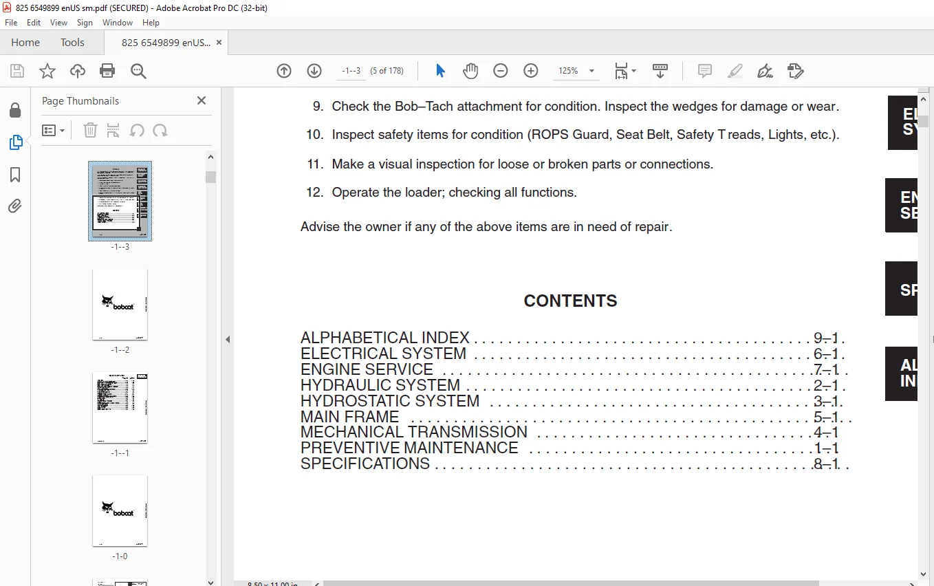
CONTENTS 5
FOREWORD 5
PREVENTIVE MAINTENANCE 7
INTRODUCTION 9
Symbols 9
Serial Number Identification 9
Loader Serial Number 9
Engine Serial Number 10
Pre-Delivery Inspection 10
30 Hour Inspection 10
SERVICE SCHEDULE 11
REAR GRILL 12
TILTING THE OPERATOR GUARD 12
ROPS Tilt Motor 13
ENGINE MAINTENANCE 13
Engine Oil 13
Specifications 13
ENGINE OIL AND FILTER REPLACEMENT 15
ENGINE AIR INLET SYSTEM (AIR CLEANER) 16
ENGINE COOLING SYSTEM 17
FAN BELT ADJUSTMENT 17
FLUSHING THE COOLING SYSTEM 17
FUEL SYSTEM 18
FUEL SPECIFICATIONS 18
Water In The Fuel Tank 18
TO SERVICE THE FUEL SYSTEM 19
REMOVE THE AIR FROM THE FUEL SYSTEM 19
ELECTRICAL SYSTEM MAINTENANCE 20
Electrical System 20
HYDRAULIC SYSTEM 21
Hydraulic/Hydrostatic Transmission Fluid 21
CHECKING AND ADDING HYDRAULIC FLUID 21
HYDRAULIC FLUID FILTERS 21
Replacement Of The Suction (25 Micron) Filter 22
Replacement Of The Return Line Filter (10 Micron) 22
DRAINING THE FLUID RESERVOIR 22
LEAKS 23
OIL COOLER 23
CARE OF THE HYDROSTATIC TRANSMISSION 23
Loader Start–Up 24
Cold Weather Start–Up 24
FINAL DRIVE CHAIN 24
TIRES 24
TIRE MAINTENANCE 25
TIRE ROTATION 25
TIRE REPLACEMENT 25
LUBRICATION 25
WHEEL MOUNTING NUTS 25
BOB–TACH 26
PARK BRAKE 26
HYDRAULIC SYSTEM 27
HYDRAULIC / HYDROSTATIC SCHEMATICS 29
HYDRAULIC SYSTEM 39
TUBELINES, HOSES, FITTINGS 39
37° Flare Connection 39
Straight Thread O–Ring Fitting (Elbows, Adapter, Etc ) 40
Pipe Thread Fittings 40
Tubelines And Hoses 40
HYDRAULIC SYSTEM TROUBLESHOOTING 40
GEAR PUMP 42
Testing 42
Removal 42
DISASSEMBLY OF GEAR PUMP 43
TO INSPECT PARTS FOR WEAR 43
General 43
Gear Assembly 43
Front And Back Plates 43
Body 44
Assembly Of Gear Pump 44
CONTROL VALVE 44
Relief Valve Check 44
Internal Leaks 45
Control Valve Repair 45
Removal 45
Disassembly 45
LIFT VALVE SPOOL (Float Detent) 46
Repair Of The Float Detent Of The Lift Spool 46
To Assemble The Detent Assembly 46
Inspection, Repair And Assembly Of Control Valve 46
CONTROL PEDALS 47
Adjustment 47
Removal Of Pedal Assembly 48
HYDRAULIC CYLINDERS 48
Checking For Internal Leak (Lift Cylinder) 48
Removal Of Lift Cylinder 48
Removal Of Tilt Cylinder 48
HYDRAULIC CYLINDER REPAIR 48
To Disassemble A Hydraulic Lift Or Tilt Cylinder 49
To Replace The Cylinder Seals 49
To Assemble The Hydraulic Cylinder 49
OIL COOLER 50
Cleaning Of Grill 50
Removal Of Oil Cooler 50
By–Pass Valve 50
Cooler By-Pass Hose 50
HYDROSTATIC SYSTEM 51
HYDROSTATIC DRIVE SYSTEM 53
Description 53
HYDROSTATIC TRANSMISSION TROUBLESHOOTING 53
CONTROL LINKAGE 58
Adjustment Of Steering Linkage 58
ADJUSTMENT OF SPEED RANGE LINKAGE 58
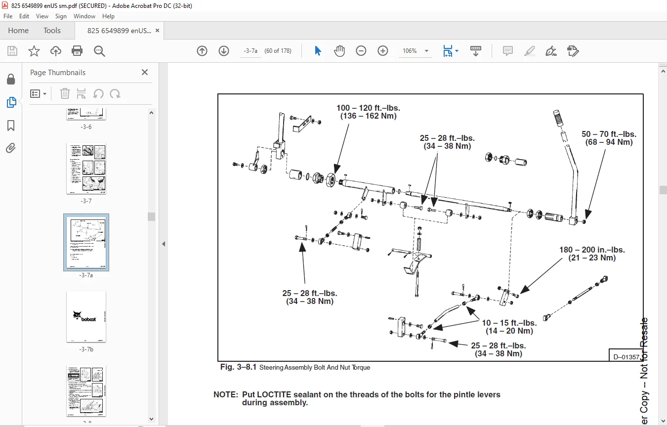
STEERING CONTROLLINKAGE 59
Removal 59
CHECKING HYDROSTATIC SYSTEM 60
Test Kit 60
Charge Pressure Check 62
Charge Pump Inlet Pressure 62
CHECKING RELIEF VALVES 63
Charge Relief Valve 63
Filter Relief Valve 63
Charge Inlet Relief Valve 63
High Pressure Relief Valve 63
MICRON FINAL FILTER ELEMENT REPLACEMENT 64
TEMPERATURE AND PRESSURE SWITCHES 64
REMOVAL OF HYDROSTATIC PUMP ASSEMBLY 65
INSTALLING HYDROSTATIC PUMP 65
REMOVAL OF HYDROSTATIC MOTOR 66
INSTALLING HYDROSTATICMOTOR 67
New Hydrostatic Pump & Motor 67
HYDROSTATIC PUMP OR MOTOR DISASSEMBLY 69
INSPECT PARTS FOR WEAR 70
TO ASSEMBLE PUMP OR MOTOR 70
STARTING PROCEDURE, AFTER REPAIR 71
FINAL DRIVE SYSTEM 73
FINAL DRIVE SYSTEM 75
Description 75
REMOVAL OF REDUCTION HOUSING 75
DISASSEMBLY OF REDUCTION HOUSING 75
Removal Of The Intermediate Gear (6) 75
Removal Of Input Drive Gear (7) 76
Removal Of Output Gear (14) 76
ASSEMBLY OF REDUCTION HOUSING 76
Installing The Output Shaft And Gear 76
Installing Input Shaft And Gear 76
Installing Intermediate Gear 76
Drive Chain Adjustment (Internal Adjustment Type) 76
Drive Chain Adjustment (External Adjustment Type) 77
Drive Chain Idler Removal (Internal Adjustment Type) 77
To Disassemble The Idler Gear (Internal) 78
Drive Chain Idler Removal (External Adjustment Type) 78
REMOVAL OF DRIVE CHAIN 79
INSTALLING DRIVE CHAIN 79
REMOVAL OF AXLE 80
Removal Of Rear Axle 80
Removal Of Front Axle 80
Installation Of The Axle 81
AXLE BEARING AND SEAL REPLACEMENT 81
NSTALLATION OF AXLES PROCKET 82
PARK BRAKE REMOVAL 82
MAIN FRAME 83
MAIN FRAME 85
Description 85
REMOVAL OF ROPS 85
PIVOT PIN AND BUSHING REPLACEMENT 85
BOB–TACH REMOVAL 85
LIFT ARMS REMOVAL 86
FUEL TANK REMOVAL 86
Removing Fuel Tank On Loader S/N 16999 & Below 86
Removing Fuel Tank On Loader S/N 17001 & Above 86
ELECTRIC MOTOR FOR ROPS (Cab Tilt – S/N 19126 & Below) 86
Removal Of Tilt Mechanism 87
MECHANICAL TILT FOR THE ROPS (S/N 19127 & Above) 87
ELECTRICAL SYSTEM 89
ELECTRICAL SCHEMATICS 93
ELECTRICAL CIRCUITRY 97
PROBLEM ANALYSIS 97
FAN BELT 99
TO CHECK ALTERNATOR OUTPUT 99
TO CHECK THE REGULATOR 99
ALTERNATOR SERVICE 100
Removal (ROPS Must Be Tilted) 100
Disassembly 100
To Check Rotor 100
To Check Stator 100
To Check Diode Trio 101
To Check Rectifier 101
Assembly 101
STARTER SERVICE 102
To Check The Starter 102
To Remove Starter 102
Disassembly And Inspection 102
Assembly 102
ENGINE SERVICE 103
INTRODUCTION 105
Engine Parts 105
Engine Number Location 105
STARTING A NEW OR RECONDITIONED ENGINE 105
ENGINE OVERHAUL 105
Engine Removal 105
Cylinder Head Maintenance 106
To Remove The Valves 107
Combustion Chamber Inserts 107
Reconditioning Cylinder Heads 108
Cleaning 108
Inspection 108
Reconditioning Of Valves AndValve Seats 109
Valve Seat Inserts 109
To Install Inserts 109
To Disassemble The Rocker Shaft Assembly 110
To Assemble The Rocker Shaft Assembly 111
Push Rods 111
To Install The Valves 111
INSTALLING CYLINDER HEAD 112
Cylinder Head Gasket 112
To Install The Cylinder Head 112
CONNECTING RODS AND PISTONS 113
To Remove Pistons And Connecting Rods 113
To Remove Pistons And Rings From The Connecting Rods 114
Inspection 114
To Install The Pistons To The Connecting Rods 114
Installing The Piston Rings 115
To Install Rings 115
To Install Piston And Connecting Rod Assemblies 116
Installing New Pistons 116
Cylinder Liners 117
To Install New Cylinder Liners 117
CRANKSHAFT AND MAIN BEARINGS 117
Description 117
To Install Main Bearings And Thrust Washers 118
To Install Thrust Washers 118
To Remove The Crankshaft 119
To Reinstall The Crankshaft 120
Crankshaft Rear End Oil Seal 121
FLYWHEEL AND FLYWHEEL HOUSING 121
To Remove The Flywheel 121
To Replace The Flywheel Ring Gear 121
To Reinstall The Flywheel 122
To Install The Flywheel Housing 122
TIMING CASE AND DRIVE 122
To Remove The Timing Case Cover 122
Replacement Of The Crankshaft Front Oil Seal 123
To Install The Timing Case Cover 123
To Remove The Idler Gear And Hub 123
To Install The Idler Gear And Hub 123
To Remove The Camshaft Gear 124
To Install The Camshaft Gear 124
To Remove The Fuel Pump Gear 124
To Install The Fuel Pump Gear 124
To Remove The Fuel Pump Drive Hub 125
To Install The Fuel Pump Drive Hub 125
To Remove The Timing CaseBack Plate 125
To Install The Timing Case Back Plate 126
To Remove The Camshaft And Tappets 126
To Install The Tappets And Camshaft 126
Timing Marks 127
To Reset The Engine To The Original Timing 127
Timing Pin 128
Check Valve Timing 128
Adjusting Valve Clearance 129
Valve Adjustment Sequence 129
LUBRICATION SYSTEM 129
The Lubricating Oil Pump 129
To Remove The Sump 129
To Install The Oil Pan 129
To Remove The Oil Pump 130
To Dismantle The Oil Pump 130
Inspection 130
To Assemble The Oil Pump 131
To Install The Oil Pump 131
Oil Pressure Relief Valve 131
To Dismantle The Oil Pressure Relief Valve 132
To Assemble The Oil Pressure Relief Valve 132
COOLING SYSTEM 132
Fan Belt 132
Adjustment Of Fan Belt 132
Water Pump 133
Remove The Water Pump 133
To Disassemble The Water Pump 133
Inspection 133
To Assemble The Water Pump 134
To Install The Water Pump 134
Thermostat 134
To Remove The Thermostat 134
To Test The Thermostat 135
Replacement Of The Thermostat 135
FUEL SYSTEM 135
To Test Fuel Lift Pump 135
To Remove The Lift Pump 135
Fuel Injection Pump 136
To Remove The Fuel Injection Pump 136
To Install The Fuel Injection Pump 136
Checking Fuel Injection Pump Timing 136
Timing The fuel Injection Pump (Using Timing Tool MS 67123) 137
Checking The Timing Mark On The Flange Of The Injection Pump 139
Injector Problems 140
Testing For Faulty Injector 140
Injector Removal 140
Injector Installation 140
Fuel Pipes (High Pressure) 140
Using C A V Thermostart Units 141
Charging The Fuel System 142
SPECIFICATIONS 143
SPECIFICATIONS 145
Cylinder Block 145
Cylinder Liner (Cast Iron) 145
Pistons 145
Piston Rings 145
Piston Pin Bushing 145
Connecting Rod 145
Connecting Rod Alignment 146
Crankshaft 146
Crankshaft Thrust Washers 146
Main Bearings 146
Connecting Rod Bearings 146
Camshaft 147
Camshaft Thrust Plates 147
Cylinder Head 147
Combustion Chamber Inserts 147
Valve Guides (Inlet) 147
Valve Guides (Exhaust) 147
Valves (Inlet) 148
Valves (Exhaust) 148
Inner Valve Springs 148
Outer Valve Springs 148
Rocker Levers 148
Valve Clearance 148
Rocker Shaft 148
Push Rods 148
Lifters 148
TIMING GEARS 149
Injector Pump Gear 149
Crankshaft Gear 149
Timing Gear Backlash 149
LUBRICATION SYSTEM 149
Lubricating Oil Pump 149
Pump Clearances 149
Lubricating Oil Pump Drive Gear 149
Relief Valve (Lube Oil) 149
Lubricating Oil Filter 149
COOLING SYSTEM 149
Thermostat 149
FUEL SYSTEM 149
Fuel Lift Pump 150
Final Fuel Filter 150
Fuel Injection Pump 150
Injectors 150
Starting Aid 150
SERVICE WEAR LIMITS 150
DE–RATING FOR ALTITUDE 151
TORQUE SPECIFICATIONS 151
Hydrostatic Pump and Motor 151
High Pressure Relief Valves 151
Loader Torque Specs 151
STANDARD TORQUE SPECIFICATIONS FOR BOLTS 152
DECIMAL AND MILLIMETER EQUIVALENTS 153
U S TO METRIC CONVERSION 153
SPECIAL TOOLS 154
825 LOADER SPECIFICATIONS 155
SPECIFICATIONS 155
ENGINE 155
LOADER HYDRAULICS 156
ELECTRICAL 156
DRIVE SYSTEM 156
CAPACITIES 156
TIRES 156
ALPHABETICAL INDEX 157
SERVICE BULLETINS 161
825-001 161
825-002 163
825-003 165
825-004 167
825-005 169
SERVICE MANUAL REVISIONS 161
825-1 171
825-2 173
825-3 175
825-4 177
DESCRIPTION:
Bobcat 825 Loader Service Manual 6549899 (6-12) – PDF DOWNLOAD
FORWARD:
This manual provides instruction for proper routine service and adjustment of the Bobcat, and
detailed overhaul instructions of the power train, loader hydraulic/hydrostatic system and
general mainframe components.
Refer to the Owner’s Manual for general operating instructions (Starting Procedure, Daily
Checks, Bucket Operation, Minor Maintenance, etc.).
A general inspection of the following items should be made whenever the machine has
undergone service or repair:
1. Check hydraulic fluid level, engine oil level and fuel supply.
2. Inspect for any sign of fuel, oil or hydraulic fluid leaks.
3. Lubricate the machine.
4. Check battery condition, electrolyte level and cables.
5. Inspect air cleaner system for damage or leaks. Check element and make replacement,
if necessary.
6. Check alternator drive belt for condition and tension.
7. Check for loose drive chains by lifting the rear of the machine and turning the rear wheels
by hand.
8. Check tires for wear and pressure.
9. Check the Bob–Tach attachment for condition. Inspect the wedges for damage or wear.
10. Inspect safety items for condition (ROPS Guard, Seat Belt, Safety Treads, Lights, etc.).
11. Make a visual inspection for loose or broken parts or connections.
12. Operate the loader; checking all functions.
Advise the owner if any of the above items are in need of repair
Questions? Email us: [email protected]
IMAGES PREVIEW OF THE MANUAL:
PLEASE NOTE:
- This is the same manual used by the DEALERSHIPS to SERVICE your vehicle.
- The manual can be all yours – Once payment is complete, you will be taken to the download page from where you can download the manual. All in 2-5 minutes time!!
- Need any other service / repair / parts manual, please feel free to contact us at heydownloadss @gmail.com . We may surprise you with a nice offer
S.V