Bobcat 843 & 843B Loader Service Manual 6566091 (6-12) – PDF DOWNLOAD
$30.95
Bobcat 843 & 843B Loader Service Manual 6566091 (6-12) – PDF DOWNLOAD
Description
Bobcat 843 & 843B Loader Service Manual 6566091 (6-12) – PDF DOWNLOAD
FILE DETAILS:
Bobcat 843 & 843B Loader Service Manual 6566091 (6-12) – PDF DOWNLOAD
Language : English
Pages : 548
Downloadable : Yes
File Type : PDF
TABLE OF CONTENTS:
Bobcat 843 & 843B Loader Service Manual 6566091 (6-12) – PDF DOWNLOAD
MAINTENANCE SAFETY 3
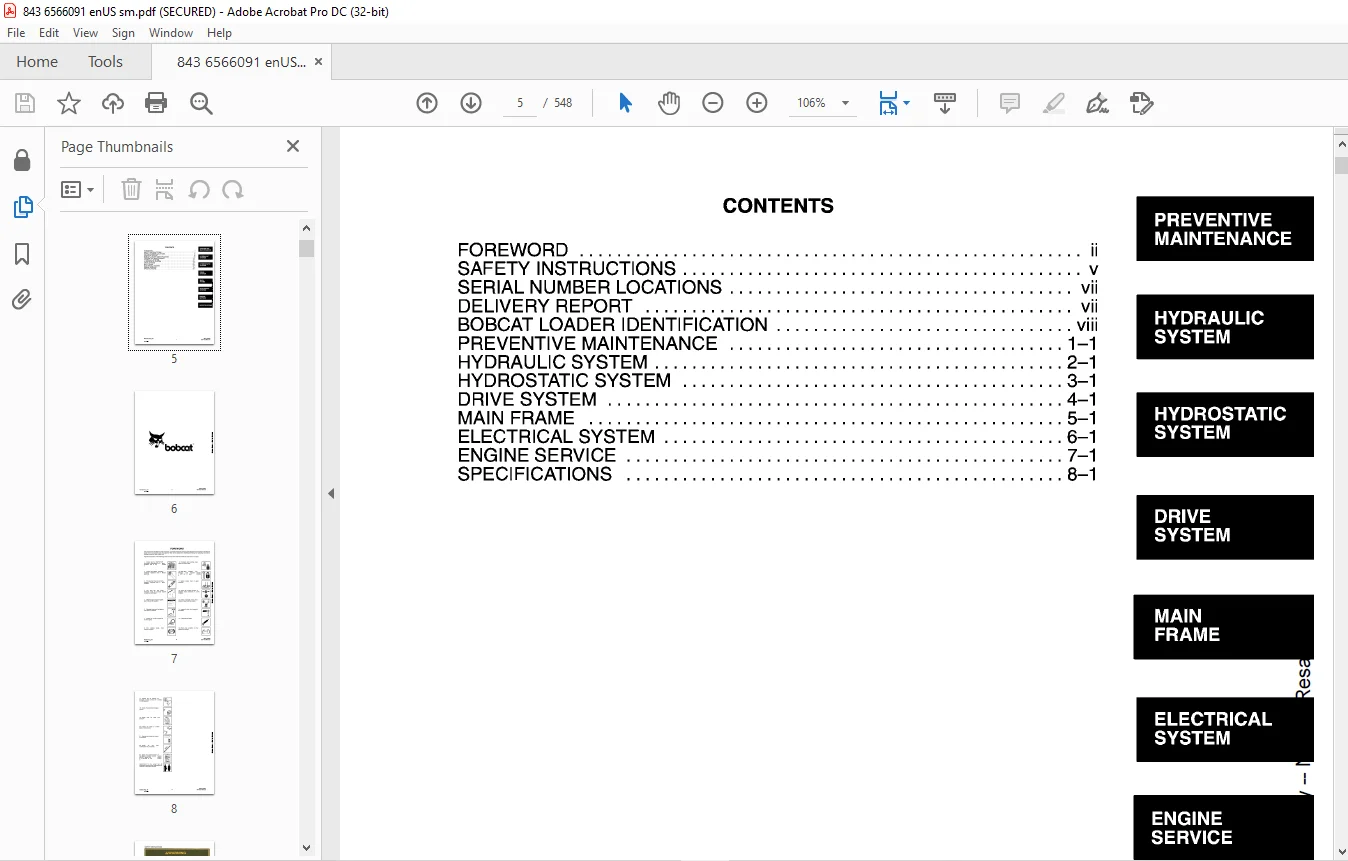
CONTENTS 5
FOREWORD 7
SAFETY INSTRUCTIONS 9
FIRE PREVENTION 10
SERIAL NUMBER LOCATIONS 11
LOADER SERIAL NUMBER 11
ENGINE SERIAL NUMBER 11
DELIVERY REPORT 11
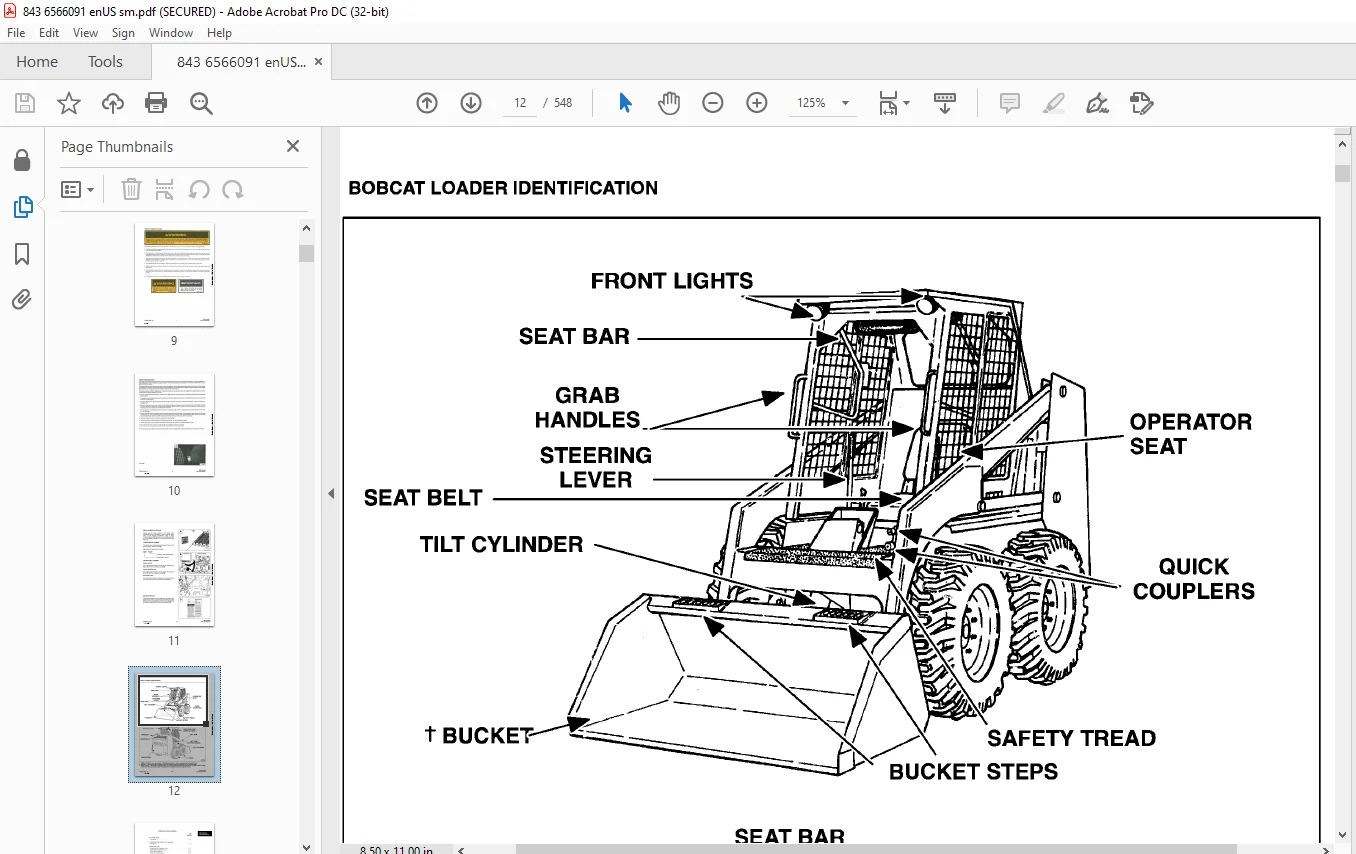
BOBCAT LOADER IDENTIFICATION 12
PREVENTIVE MAINTENANCE 13
SERVICE SCHEDULE 15
LIFTING AND BLOCKING THE LOADER 16
Procedure 16
TRANSPORTING THE BOBCAT LOADER 17
Procedure 17
LIFT ARM STOP 18
Procedure 18
OPERATOR CAB 19
Seat Bar System 19
Seat Bar Inspection 19
Seat Bar Maintenance 20
Raising The Operator Cab 21
Lowering The Operator Cab 21
USING AN EXTRA BATTERY (JUMP STARTING) 22
Procedure 22
REMOTE START SWITCH 23
Procedure 23
HYDRAULIC SYSTEM 25
HYDRAULIC / HYDROSTATIC SCHEMATICS 27
TROUBLESHOOTING 79
HYDRAULIC SYSTEM INFORMATION 80
Flare Connections 80
Straight Thread O-Ring Fitting 80
Tubelines And Hoses 80
LIFT CYLINDER 81
Checking The Lift Cylinder(s) 81
Removal And Installation 81
TILT CYLINDERS 83
Checking The Tilt Cylinder 83
Removal And Installation 83
Rod End Seal 84
TILT CYLINDER (CESSNA) 85
Disassembly 85
Assembly 87
HYDRAULIC CYLINDER REPAIR 91
Disassembly 91
Assembly 93
HYDRAULIC CONTROL VALVE (CESSNA) 96
Checking The Main Relief Valve 96
Main Relief Valve Removal And Installation 97
Removal And Installation 97
Disassembly 99
Inlet Section 100
Tilt Section 101
Lift Section 103
Auxiliary Section 105
Valve Spool Bolt 106
Assembly 107
HYDRAULIC CONTROL VALVE (MELROE) 108
Checking The Main Relief Valve 108
Main Relief Valve Removal And Installation 109
Removal And Installation 109
Disassembly And Assembly 111
Detent Assembly 113
Centering Mechanism 116
HYDRAULIC PUMP (SINGLE STAGE) 117
Checking The Output Of The Hydraulic Pump 117
Removal And Installation 118
Disassembly And Assembly 118
Inspection 120
HYDRAULIC PUMP (DOUBLE STAGE) 121
Removal And Installation 122
Disassembly And Assembly 124
Inspection 126
BUCKET POSITION VALVE (S/N 15001 & ABOVE) 127
Removal And Installation 127
Disassembly And Assembly 127
PORT BLOCK (S/N 14999 & BELOW) 129
40 Micron Filter (Bronze) 129
Neutral By-Pass Valve 130
Removal And Installation 130
PORT BLOCK (S/N 15001 & ABOVE) 133
Removal And Installation 133
Charge By-Pass 134
Cold Oil By-Pass 134
HYDRAULIC FLUID FILTER HOUSING (S/N 15001 & ABOVE) 135
Removal And Installation 135
By-Pass Valve 135
HYDRAULIC/HYDROSTATIC RESERVOIR (S/N 21514 & BELOW) 136
Removal And Installation 136
HYDRAULIC CONTROL PEDALS (S/N 14999 & BELOW) 138
Removal And Installation 138
Adjustment 138
HYDRAULIC CONTROL PEDALS (S/N 15001 & ABOVE) 139
Removal And Installation 139
Adjustment 139
PEDAL LOCK LINKAGE 140
Adjustment 140
HYDROSTATIC SYSTEM 141
TROUBLESHOOTING 143
HYDROSTATIC SYSTEM INFORMATION 144
High Pressure Relief/Replenishing Valves Function 144
FRONT AND SIDE PANELS (S/N 19999 & BELOW) 145
Removal And Installation 145
STEERING LEVERS (S/N 16191 & BELOW) 146
Removal And Installation 146
Repairing The Steering Levers 147
Steering Linkage Adjustment 148
Removal And Installation 149
RepairingThe Pintle Lever 150
FRONT AND SIDE PANEL (ONE PIECE) (S/N 20001 & ABOVE) & 843B 151
Removal And Installation 151
STEERING LEVERS – 843-(S/N 16192 THRU 25999), 843-(STARTING WITH S/N 34222) & 843B 154
Removal And Installation 154
Repairing The Steering Levers 155
STEERING LINKAGE 843-(S/N 16192 THRU 25999), 843-(STARTING WITH S/N 34222) & 843B 156
Steering Linkage Adjustment 156
Removal And Installation 157
Repairing The Pintle Lever 158
STEERING LINKAGE (S/N 26000 THRU 29869) 159
Description 159
Neutral Adjustment 159
Steering Lever Centering Spring Mechanism 161
Removal And Installation (Creep Mechanism) 162
SERVO CONTROL 165
Removal And Installation 165
Disassembly And Assembly 166
PINTLE LEVER ARMS (S/N 26000 – 29869) 167
Removal And Installation 167
STEERING LINKAGE (S/N 29870 – 31863) 169
Description 169
Neutral Adjustment 169
Steering Lever Centering Spring Mechanism 171
Creep Centering Spring Mechanism 171
Pintle Arm 171
STEERING LINKAGE (S/N 31864-34221) 172
Hydrostatic Pump Centering Spring Adjustment 173
Servo Control Unit Adjustment 174
Steering Lever Centering Spring Adjustment 175
Wheel RPM Adjustment (Left To Right) 176
HYDROSTATIC MOTOR 178
Removal And Installation 178
Disassembly And Assembly 179
Inspection 183
Timing The Hydrostatic Motor 184
High Pressure Hose Routing 184
HYDROSTATIC PUMPS 185
Checking The High Pressure Relief/Replenishing Valve 185
Checking Charge Pressure 186
Removal And Installation 186
Disassembly And Assembly 187
Rear Pump 189
Front Pump 189
Inspection 192
Tow Valves 193
Hydrostatic Pump Rear Mount (S/N 21574 & Above) 194
HYDROSTATIC FLUID FILTER HOUSING 195
Removal And Installation 195
DRIVE SYSTEM 197
PARKING BRAKE 199
Adjustment 199
Removal And Installation 199
Block And Pucks 200
AXLES, SEALS AND BEARINGS 202
Removal 202
Installation 203
FINAL DRIVE CHAIN 206
Removal 206
Installation 206
REDUCTION GEARCASE 208
Removal And Installation 208
Checking Reduction Gearcase 209
Disassembly And Assembly 209
Installation 214
Reduction Gearcase Seal 215
MAIN FRAME 217
OPERATOR CAB (S/N 19999 & BELOW) 219
Removal And Installation 219
OPERATOR CAB (S/N 20001 & ABOVE) 221
Removal And Installation 221
OPERATOR CAB GAS CYLINDER 224
Removal And Installation 224
REAR DOOR 225
Door Latch Adjustment 225
Removal And Installation 226
LIFT ARMS 227
Removal And Installation 227
BOB-TACH 229
Removal And Installation 229
Tilt Cylinder Rod End Seal 230
Disassembly And Assembly 231
FUEL TANK (S/N 19999 & BELOW) 233
Removal And Installation 233
FUEL TANK (S/N 20001 & ABOVE) 234
Removal And Installation 234
Fuel Tank Sender Switch 235
ELECTRICAL SYSTEM 237
ELECTRICAL SCHEMATICS 240
ELECTRICAL SYSTEM INFORMATION 267
Description 267
TROUBLESHOOTING 267
BATTERY 268
Checking The Battery 268
Removal And Installation 268
ALTERNATOR 269
Alternator Belt Adjustment 269
Checking The Alternator Wire Harness 270
Checking Alternator Output 270
Checking Alternator Regulator 270
Removal And Installation 271
Disassembly And Assembly 272
MELROE ALTERNATOR 274
Checking The Alternator Output 274
Checking The Alternator Regulator 275
Removal And Installation 276
Disassembly And Assembly 277
MANDO ALTERNATOR 279
STARTER 280
Checking The Starter 280
Removal And Installation 280
Disassembly And Assembly 282
Cleaning And Inspection 282
Replacing The Brushes 283
ENGINE SERVICE 285
ENGINE SERVICE (PERKINS ENGINE) 287
TROUBLESHOOTING 289
VALVE CLEARANCE 290
Adjustment 290
ENGINE COMPRESSION 291
Checking 291
FUEL FILTER 292
Removal And Installation 292
Water Trap 292
FUEL LIFT PUMP 293
Checking 293
Removal And Installation 293
REMOVING AIR FROM FUEL SYSTEM 294
Procedure 294
FUEL INJECTION PUMP 295
Removal And Installation 295
ENGINE TIMING TO INJECTION PUMP (USING DIAL INDICATOR) 296
Procedure 296
EMGINE TIMING TO INJECTOR PUMP (USING TIMING TOOL) 297
Procedure 297
CHECKING TIMING MARK ON INJECTION PUMP FLANGE 298
Procedure 298
FUEL INJECTOR NOZZLES 299
Removal And Installation 299
Checking 300
ENGINE 301
Removal And Installation 301
RADIATOR 305
Removal And Installation 305
OIL COOLER 306
Removal And Installation 306
ENGINE MUFFLER 307
Removal And Installation 307
ENGINE BLOWER HOUSING 308
Removal And Installation 308
ENGINE FLYWHEEL & U-JOINT 309
Removal And Installation 309
Flywheel Ring Gear 309
CYLINDER HEAD 310
Removing The Cylinder Head 310
Cylinder Head Surface Alignment 310
Installing The Cylinder Head 311
VALVES 312
Removal Of The Valves 312
Installing The Valves 312
Reconditioning The Valves And Valve Seats 312
Installing Valve Guides 313
Changing The Valve Springs 314
COMBUSTION CHAMBER INSERTS 315
Removal And Installation 315
ROCKER ARMS 316
Disassembly 316
Assembly 316
PISTON AND CONNECTING RODS 317
Removal 317
Disassembly 318
Inspection 318
Installation 319
CYLINDER LINERS 320
Checking 320
Removal And Installation 320
MAIN BEARINGS 321
Removal 321
Installation 322
Crankshaft End Play 322
CRANKSHAFT 323
Removal 323
Checking 323
Installation 324
REAR MAIN OIL SEAL 325
Removal And Installation 325
TIMING CASE COVER 326
Removal And Installation 326
IDLER GEAR AND HUB 327
Removal 327
Installation 327
CAMSHAFT GEAR 329
Removal 329
Installation 329
FUEL INJECTION PUMP DRIVE GEAR 330
Removal And Installation 330
CRANKSHAFT GEAR 330
Removal 330
TIMING CASE 331
Removal And Installation 331
CAMSHAFT AND TAPPETS 332
Removal 332
Inspection 333
Installation 333
LUBRICATION SYSTEM 334
Description 334
OIL PUMP 335
Removal And Installation 335
Disassembly And Assembly 335
Checking 335
WATER PUMP 337
Removal And Installation 337
Disassembly 337
Checking 338
Assembly 338
THERMOSTAT 339
Removal 339
Testing The Thermostat 339
Installation 339
ENGINE SERVICE (PERKINS ENGINE – 200 SERIES) 341
TROUBLESHOOTING 343
VALVE CLEARANCE 344
Adjustment 344
ENGINE COMPRESSION 345
Checking 345
FUEL FILTER (S/N 13315 & BELOW) 346
Removal And Installation 346
Water Trap 346
FUEL FILTER (S/M 13316 & ABOVE) 346
Removal And Installation 346
REMOVING AIR FROM THE FUEL SYSTEM (S/N 13315 & BELOW) 347
Procedure 347
REMOVING AIR FROM THE FUEL SYSTEM (S/N 13316 & ABOVE) 348
Procedure 348
FUEL INJECTION PUMP 349
Removal And Installation 349
Maximum Speed Setting 350
TIMING THE FUEL INJECTION PUMP 351
Procedure 351
FUEL INJECTOR NOZZLES 353
Removal And Installation 353
Checking 354
GLOW PLUGS 355
Checking 355
ENGINE 356
Removal And Installation 356
RADIATOR 359
Removal And Installation 359
OIL COOLER 361
Removal And Installation 361
ENGINE MUFFLER 362
Removal And Installation 362
ENGINE BLOWER HOUSING 363
Removal And Installation 363
ENGINE FLYWHEEL & U-JOINT 364
Removal And Installation 364
Flywheel Ring Gear 364
CYLINDER HEAD 365
Removing The Cylinder Head 365
Cylinder Head Surface Alignment 365
Installing The Cylinder Head 366
VALVES 367
Removing The Valves 367
Installing The Valves 367
Reconditioning The Valves And Valve Seats 367
Installing The Valve Guides 368
Checking The Valve Springs 369
CONBUSTION CHAMBER INSERTS 370
Removal And Installation 370
ROCKER ARMS 371
Disassembly 371
Assembly 371
PISTON AND CONNECTING RODS 372
Removal 372
Disassembly 373
Inspection 373
Installation 374
CYLINDER LINERS 375
Checking 375
Removal And Installation 375
MAIN BEARINGS 376
Removal 376
Installation 377
Crankshaft End Play 377
CRANKSHAFT 378
Removal 378
Installation 379
REAR MAIN OIL SEAL 380
Removal And Installation 380
TIMING CASE COVER 381
Removal And Installation 381
Front Seal 382
IDLER GEAR AND HUB 383
Removal 383
Installation 384
CAMSHAFT GEAR 385
Removal 385
Installation 385
FUEL INJECTION PUMP DRIVE GEAR 386
Removal And Installation 386
CRANKSHAFT GEAR 386
Removal 386
TIMING CASE 387
Removal And Installation 387
CAMSHAFT AND TAPPETS 388
Removal 388
Inspection 389
Installation 389
LUBRICATION SYSTEM 390
Description 390
OIL PUMP 391
Removal And Installation 391
Inspection 392
OIL FILTER ADAPTER HOUSING 393
Removal And Installation 393
WATER PUMP 394
Removal And Installation 394
Disassembly 394
Checking 395
Assembly 395
THERMOSTAT 396
Removal 396
Testing The Thermostat 396
Installation 396
ENGINE SERVICE (ISUZU ENGINE) 397
TROUBLESHOOTING 399
VALVE CLEARANCE 400
Adjustment 400
ENGINE COMPRESSION 401
Checking 401
FUEL FILTER 402
Water Trap 402
Fuel Filter Element 402
REMOVING AIR FROM FUEL SYSTEM 403
Procedure 403
FUEL INJECTION PUMP 404
Removal And Installation 404
ENGINE TIMING TO INJECTION PUMP 407
Procedure 407
FUEL INJECTOR NOZZLES 409
Removal And Installation 409
Checking 410
GLOW PLUGS 412
Removal And Installation 412
ENGINE OIL AND FILTER 413
Removal And Installation 413
ENGINE 415
Removal And Installation 415
RADIATOR 420
Removal And Installation 420
OIL COOLER 422
Removal And Installation 422
ENGINE MUFFLER 423
Removal And Installation 423
ENGINE FLYWHEEL & U-JOINT 424
Removal And Installation 424
Flywheel Ring Gear 424
ENGINE BLOWER HOUSING 425
Removal And Installation 425
ENGINE MOUNTS 426
Removal And Installation 426
CYLINDER HEAD 427
Removal And Installation 427
Cylinder Head Surface Alignment 428
Exhaust Manifold 428
VALVES 429
Removal And Installation 429
Reconditioning The Valves And Valve Seats 429
Valve Seat Insert 430
Valve Guides 430
Valve Springs 431
ROCKER ARMS 432
Disassembly And Assembly 432
Push Rods 432
PISTON AND CONNECTING ROD 433
Removal 433
Disassembly 433
Inspection 434
Assembly 437
Installation 438
CYLINDER LINERS 439
Checking 439
Removal 439
Installation 439
MAIN BEARINGS 440
Removal 440
Installation 441
Crankshaft End Play 442
CRANKSHAFT 443
Removal 443
Checking Tuffriding (Soft Nitriding) Coating 443
Checking 443
Crankshaft Gear 445
Removal And Installation 445
Installation 445
TIMING CASE COVER SEAL 446
Removal And Installation 446
TIMING CASE COVER 447
Removal And Installation 447
IDLER GEAR AND HUB 449
Removal And Installation 449
Checking 449
FUEL INJECTION PUMP IDLER GEAR 451
Removal And Installation 451
Bearing Installation 451
CAMSHAFT GEAR 452
Removal And Installation 452
TIMING CASE 453
Removal And Installation 453
CAMSHAFT 454
Removal And Installation 454
Checking 454
Camshaft Bearing 455
Tappets 455
Installation 456
OIL PAN 457
Removal 457
Installation 457
OIL PUMP 458
Removal And Installation 458
Checking 458
Gear Replacement 459
Rotor Replacement 460
Oil Pump Relief Valve 460
WATER PUMP 461
Removal And Installation 461
Disassembly 461
Assembly 462
THERMOSTAT 464
Removal And Installation 464
Inspection 464
WATER JACKET TUBE 465
Removal And Installation 465
TECHNICAL DATA 467
GENERAL SPECIFICATIONS 469
TORQUE SPECIFICATIONS 471
Seat Bar, Fuel Tank & Panel Group 471
Steering Levers, Linkage & Pedal Group 472
Brakem Axle & Chaincase Group 473
Operator Guard, Lift Arm & Main Frame Group 474
Hydraulic/Hydrostatic Group 475
Engine Group (Perkins) 476
Engine Group (200 Series Perkins) 478
Engine Group (Isuzu) 480
HYDRAULIC/HYDROSTATIC FLUID SPECIFICATIONS 482
DECIMAL AND MILLIMETER EQUIVALENTS 483
U S TO METRIC CONVERSION 483
STANDARD TORQUE SPECIFICATIONS FOR BOLTS 484
TECHNICAL DATA (PERKINS ENGINE) 485
LOADER SPECIFICATIONS 487
Specifications 487
Engine 487
Loader Hydraulics 488
Electrical 488
Drive System 488
Capacities 488
Tires 488
ENGINE SPECIFICATIONS 489
Cylinder Head Dimensions 489
Piston And Connecting Rod Dimensions 490
Cylinder Block And Liner Dimensions 491
crankshaft And Main Bearings Dimensions 491
Timing Case, Camshaft And Drive Dimensions 492
Oil Pump Dimensions 493
Cooling System and Wster Pump Dimensions 494
Fuel System Specifications 494
De-Rating For Altitude 495
Engine Torque 495
Grinding Specifications For Crankshaft 496
TECHNICAL DATA (PERKINS ENGINE – 200 SERIES) 497
LOADER SPECIFICATIONS 499
Specifications 499
Engine 499
Loader Hydraulics 500
Electrical 500
Drive System 500
Capacities 500
Tires 500
ENGINE SPECIFICATIONS 501
Cylinder Head Dimensions 501
Pistons And Connecting Rod Dimensions 501
Cylinder Block And Liner Dimensions 502
Crankshaft And Main Bearing Dimensions 502
Timing Case, Camshaft And Drive Dimensions 503
Oil Pump Dimensions 503
Cooling System And Water Pump Dimensions 503
Fuel System Specifications 504
De-Rating For Altitude 504
Engine Torques 504
Grinding Specifications For Crankshaft 505
TECHNICAL DATA (iSUZU ENGINE) 507
LOADER SPECIFICATIONS 509
Operation And Performance 509
Engine 509
Loader Hydraulics 510
Electrical 510
Drive System 510
Capacities 510
Tires 510
ENGINE SPECIFICATIONS 511
Cylinder Head 511
Valve, Vale Guide And Seat Insert 511
Valve Springs 511
Rocker Arm 511
Tappets 512
Piston, Pin And Rings 512
Connecting Rod & Bearing 512
Cylinder Liners 512
Camshaft 512
Crankshaft 513
Idler Gear 513
Oil Pump 513
Fuel System 513
Engine Torque 514
SERVICE MANUAL REVISIONS 515
843-1 515
843-2 517
843-3 519
843-4 521
843-5 523
843-6 525
843-7 527
843-8 529
843-9 531
843-10 533
843-11 535
843-12 537
843-13 539
843-14 541
843-15 543
843-16 545
843-17 547
DESCRIPTION:
Bobcat 843 & 843B Loader Service Manual 6566091 (6-12) – PDF DOWNLOAD
FOREWORD:
This manual is for the Bobcat loader mechanic. lt provides necessary servicing and adjustment procedures for the Bobcat
loader and its component parts and systems. Refer to the Operation & Maintenance Manual for operating instructions,
starting procedure, daily checks, etc.
SAFETY INSTRUCTIONS
The following publications provide information on the safe use and maintenance of the loader and attachments:
• The Delivery Report is used to assure that complete instructions have been given to the new owner and that the machine
is in safe operating condition.
• The Operation & Maintenance Manual delivered with the loader gives operating information as well as routine
maintenance and service procedures. It is a part of the loader and must stay with the machine when it is sold.
Replacement Operation & Maintenance Manuals can be ordered from your Bobcat loader dealer.
• The loader has machine signs (decals) which instruct on the safe operation and care. The signs and their locations are
shown in the Operation & Maintenance Manual. Replacement signs are available from your Bobcat loader dealer.
• The loader has a plastic Operator’s Handbook fastened to the operator cab. Its brief instructions are convenient to the
operator. The handbook is available from your dealer in English edition or a combination English, French, German,
Italian, Dutch & Spanish edition.
• The EMI Safety Manual (available in Spanish) delivered with the loader gives general safety information.
• The Service Manual and Parts Manual are available from your dealer for use by mechanics to do shop–type service and
repair work.
• The Skid–Steer Loader Operator Training Course is available through your local dealer. This course is intended to
provide rules and practices for correct operation of the Bobcat loader. The course is available in English and Spanish
version.
• The Bobcat Skid–Steer Loader Safety Video is available from your Bobcat Dealer.
Contact us: [email protected]
IMAGES PREVIEW OF THE MANUAL:
PLEASE NOTE:
- This is the same manual used by the dealers to diagnose and troubleshoot your vehicle
- You will be directed to the download page as soon as the purchase is completed. The whole payment and downloading process will take anywhere between 2-5 minutes
- Need any other service / repair / parts manual, please feel free to contact [email protected] . We still have 50,000 manuals unlisted
S.V