Bobcat 853 & 853H Loader Service Manual 6720755 (6-12) – PDF DOWNLOAD
$28.95
Bobcat 853 & 853H Loader Service Manual 6720755 (6-12) – PDF DOWNLOAD
(S/N 508411001–508417999)
(S/N 509711001–509717999)
(S/N 510250001 & Above)
(S/N 510375001 & Above)
(S/N 512815001–512815999)
(S/N 510125001 & Above)
(S/N 512311001 & Above)
Description
Bobcat 853 & 853H Loader Service Manual 6720755 (6-12) – PDF DOWNLOAD
FILE DETAILS:
Bobcat 853 & 853H Loader Service Manual 6720755 (6-12) – PDF DOWNLOAD
Language : English
Pages : 398
Downloadable : Yes
File Type : PDF
TABLE OF CONTENTS:
Bobcat 853 & 853H Loader Service Manual 6720755 (6-12) – PDF DOWNLOAD
MAINTENANCE SAFETY 3
ALPHABETICAL INDEX 5
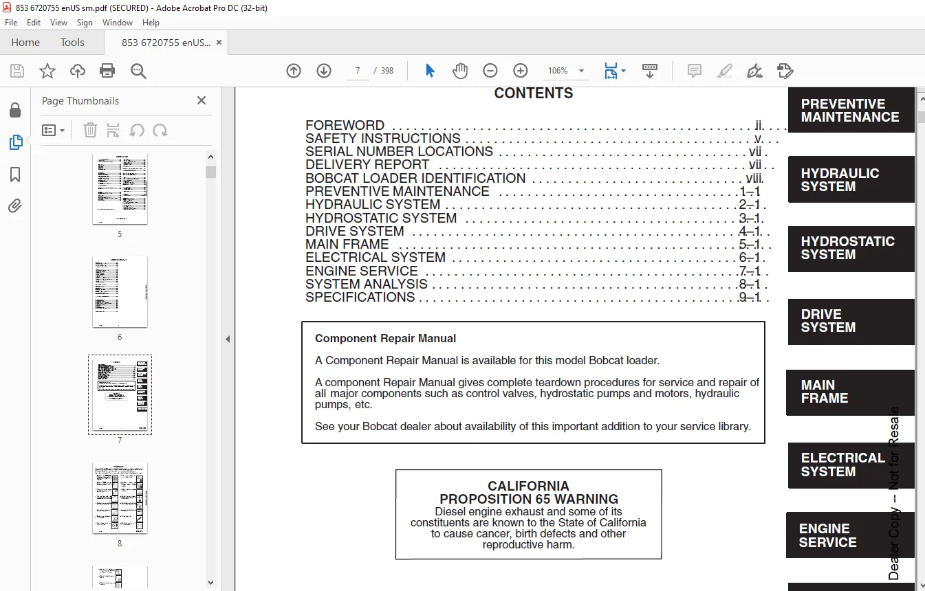
CONTENTS 7
FOREWORD 8
SAFETY INSTRUCTIONS 11
SERIAL NUMBER LOCATIONS 13
LOADER SERIAL NUMBER 13
ENGINE SERIAL NUMBER 13
DELIVERY REPORT 13
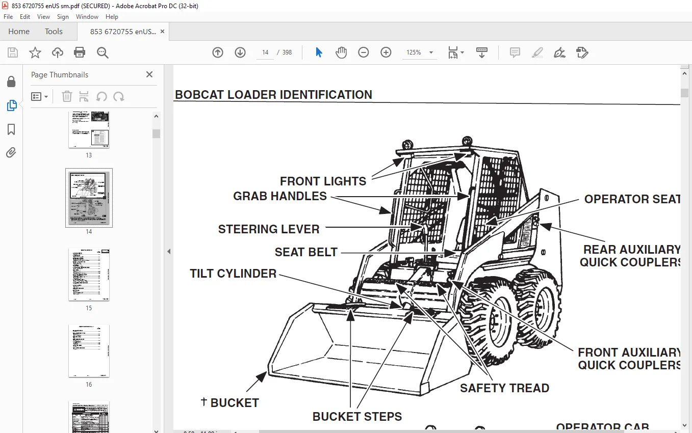
BOBCAT LOADER IDENTIFICATION 14
PREVENTIVE MAINTENANCE 15
SERVICE SCHEDULE 17
LIFTING AND BLOCKING THE LOADER 18
Procedure 18
TRANSPORTING THE LOADER 19
Procedure 19
TOWING THE LOADER 19
Procedure 19
LIFTING THE LOADER 20
Four Point Lift 20
Single Point Lift 20
LIFT ARM SUPPORT DEVICE 21
Engaging The Lift Arm Support Device 21
Disengaging The Lift Arm Support Device 22
OPERATOR CAB 23
Description 23
Raising The Operator Cab 23
Lowering The Operator Cab 24
Emergency Exit 24
SEAT BAR RESTRAINT SYSTEM 25
Description 25
Inspecting The Seat Bar 25
Maintaining The Seat Bar 25
AIR CLEANER SERVICE 26
Replacing Filter Element 26
FUEL SYSTEM 28
Fuel Specifications 28
Filling The Fuel Tank 28
Fuel Filter 28
Removing Air From The Fuel System 29
ENGINE LUBRICATION SYSTEM 30
Checking Engine Oil 30
Replacing Oil And Filter 30
ENGINE COOLING SYSTEM 32
Checking The Coolant Level 32
Cleaning The Cooling System 32
Replacing The Coolant 33
ALTERNATOR BELT 34
Adjusting The Alternator Belt 34
HYDRAULIC/HYDROSTATIC SYSTEM 35
Checking And Adding Fluid 35
Replacing Hydraulic/Hydrostatic Filters 35
Replacing The Hydraulic Fluid 36
Hydraulic Reservoir Breather Cap 37
SPARK ARRESTOR MUFFLER 38
Cleaning Procedure 38
TIRE MAINTENANCE 39
Wheel Nuts 39
Tire Rotation 39
Tire Mounting 39
FINAL DRIVE TRANSMISSION (CHAINCASE) 40
Checking And Adding Oil 40
FAN GEARBOX 40
Checking And Maintaining 40
LUBRICATING THE LOADER 41
Procedure 41
REMOTE START SWITCH 43
Procedure 43
HYDRAULIC SYSTEM 45
HYDRAULIC/HYDROSTATIC SCHEMATICS 47
TROUBLESHOOTING 73
HYDRAULIC SYSTEM INFORMATION 74
Tighten Procedures 74
LIFT CYLINDER(S) 75
Checking The Lift Cylinder 75
Removal And Installation 75
TILT CYLINDER 77
Checking The Tilt Cylinder 77
Rod End Seal 78
HYDRAULIC CYLINDER 79
Lift Cylinder Identification 79
Tilt Cylinder Identification 80
Disassembly 81
Assembly 83
MAIN RELIEF VALVE 86
Checking The Main Relief Valve 86
Checking The Main Relief Valve Without Auxiliaries 87
Removal And Installation 88
DUAL PRESSURE MAIN RELIEF VALVE (S/N 512811001 & Above) W/ Select Valve (JEM) 89
Checking The Low Setting 89
Checking The High Setting 90
Adjusting The Low Setting 92
Adjusting The High Setting 93
HYDRAULIC CONTROL VALVE 94
Removal And Installation 94
SELECT VALVE (S/N 512811001 & Above) W/SelectValve (JEM) 96
Checking The Relief Valve 96
Removal And Installation 98
Disassembly And Assembly 99
Solenoid Testing 100
HYDRAULIC FILTER HOUSING 101
Removal And Installation 101
HYDRAULIC PUMP 102
Checking The Output Of The Pump 102
Removal And Installation 103
HYDRAULIC FLUID RESERVOIR 104
Removal And Installation 104
LOCK VALVE (S/N 5103) 105
Removal And Installation 105
BUCKET POSITION VALVE (S/N 5102) & (S/N 5103) 106
Removal And Installation 106
FRONT AUXILIARY CONTROL VALVE (Apitech) 107
Removal And Installation 107
CONTROL PEDALS 108
Removal And Installation 108
Pedal Adjustment 108
PEDAL INTERLOCK LINKAGE 109
Removal And Installation 109
Pedal Interlock Linkage Adjustment 110
HYDROSTATIC SYSTEM 111
TROUBLESHOOTING 113
HYDROSTATIC SYSTEM INFORMATION 114
Replenishing Valve Function 114
Tow Valves 114
FRONT PANEL 115
Removal And Installation 115
STEERING LEVERS 117
Disassembly And Assembly 117
Neutral Pre–Adjustment Checks 119
Adjusting Lever Freeplay 120
Adjusting The Wheel RPM Forward Compared To Reverse Travel 121
Adjusting The Steering Neutral Setting 123
Adjusting The Wheel RPM Left Compared To Right Side 124
Hydrostatic Pump Neutral Adjustment 125
HYDROSTATIC MOTOR 127
Removal And Installation 127
HYDROSTATIC CHARGE OIL FILTER 129
Removal And Installation 129
COLD OIL BY–PASS VALVE 131
Removal And Installation 131
HYDROSTATIC PUMP 133
Removal And Installation 133
Replenishing/High Pressure Relief Valve 135
DRIVE BELT SHIELD 136
Removal And Installation 136
DRIVE BELT 137
Replacing The Drive Belt 137
SPRING LOADED TENSIONER PULLEY 138
Parts Identification 138
Disassembly 139
Assembly 140
Adjusting The Drive Belt 142
FIXED TENSIONER PULLEY 143
Removal And Installation 143
Disassembly 144
Assembly 146
Checking Pulley End Play 150
Adjusting The Drive Belt 151
OIL COOLER 152
Removal And Installation 152
DRIVE SYSTEM 153
PARKING BRAKE PEDAL 155
Adjustment 155
PARKING BRAKE 156
Removal And Installation 156
Brake Block And Pads 158
Brake Discs 159
FRONT CHAINCASE COVER 160
Removal And Installation 160
REAR CHAINCASE COVER 160
Removal And Installation 160
AXLE SEAL 161
Removal And Installation 161
AXLE, SPROCKET AND BEARINGS 163
Removal And Installation 163
REDUCTION GEARCASE 167
Reduction Gearcase Seal 167
Removal And Installation 168
Checking Reduction Gearcase 169
Disassembly 169
Assembly 174
DRIVE CHAIN 178
Removal And Installation 178
CHAINCASE FLUID 179
Removing The Fluid From The Chaincase 179
MAIN FRAME 181
OPERATOR CAB GAS CYLINDER 183
Removal And Installation 183
Disassembly And Assembly 184
OPERATOR CAB 185
Removal And Installation 185
BOB–TACH 187
Removal And Installation 187
Bob–Tach Lever And Wedge 189
Bob–Tach Stops 190
LIFT ARMS 191
Removal And Installation 191
REAR GRILL 192
Removal And Installation 192
REAR DOOR 193
Removal And Installation 193
Hood Removal And Installation 194
Bumper Removal And Installation 194
Door Latch Removal And Installation 194
Door Latch And Catch Adjustment 194
FUEL TANK 195
Removal And Installation 195
Inlet Screen 196
ELECTRICAL SYSTEM 197
ELECTRICAL SCHEMATICS 199
TROUBLESHOOTING 231
ELECTRICAL SYSTEM INFORMATION 232
Description 232
Fuse Location 232
BATTERY 233
Removal And Installation 233
Servicing The Electrical System 234
Using A Booster Battery (Jump Starting) 235
ALTERNATOR 236
Alternator Output Test 236
Rectifier (Diode) Test 236
Alternator Regulator Test 237
Removal And Installation 238
Disassembly 239
Stator Continuity Test 239
Stator Ground Test 239
Rotor Continuity Test 240
Rotor Ground Test 240
Rectifier Continuity (Diode) Test 240
Assembly 241
STARTER 242
Checking The Starter 242
Removal And Installation 243
Parts Identification 244
Disassembly And Assembly 245
Cleaning And Inspection 247
STANDARD INSTRUMENT PANEL 248
Removal And Installation 248
FRONT LIGHTS 249
Removal And Installation 249
STEERING LEVER CONTROL HANDLE (Early Series) 250
Disassembly And Assembly 250
ENGINE SERVICE 251
TROUBLESHOOTING 255
ENGINE SPEED CONTROL 256
Removal And Installation 256
ENGINE MUFFLER 257
Removal And Installation 257
AIR CLEANER HOUSING 258
Removal And Installation 258
COOLANT RECOVERY TANK 259
Removal And Installation 259
RADIATOR 260
Removal And Installation 260
FAN DRIVE TENSION PULLEY 262
Removal And Installation 262
FAN GEARBOX/BLOWER HOUSING 263
Removal And Installation 263
FAN GEARBOX 267
Parts Identification 267
Disassembly 268
Assembly 272
Checking Backlash 277
ENGINE 280
Removal And Installation 280
FLYWHEEL 287
Removal And Installation 287
Flywheel Ring Gear 287
BELT SHIELD 288
Removal And Installation 288
ENGINE MOUNTS 289
Removal And Installation 289
GLOW PLUGS 290
Checking The Glow Plugs 290
Removal And Installation 290
VALVE CLEARANCE 291
Adjustment 291
ENGINE COMPRESSION 291
Checking 291
FUEL INJECTION PUMP 292
Description 292
Removal And Installation 292
Timing The Injection Pump 296
FUEL INJECTOR NOZZLES 298
Checking 299
Removal And Installation 298
CYLINDER HEAD 301
Removal And Installation 301
Cylinder Head Surface Alignment 302
Exhaust Manifold 302
VALVES, VALVE SEAT AND GUIDE 303
Removal 303
Installation 303
Reconditioning The Valve And Valve Seats 303
Valve Seat Insert 304
Valve Guide 304
Valve Spring 305
ROCKER ARM AND SHAFT 306
Disassembly And Assembly 306
Checking Rocker Arm And Push Rods 306
PISTON AND CONNECTING ROD 307
Removal 307
Disassembly 307
Checking 308
Assembly 311
Installation 312
CYLINDER LINERS 313
Checking The Cylinder Bore 313
Removal 313
Installation 313
MAIN BEARINGS 314
Description 314
Removal 314
Installation 315
Crankshaft End Play 316
CRANKSHAFT 317
Removal And Installation 317
Checking The Crankshaft 317
CRANKSHAFT GEAR 319
Removal And Installation 319
TIMING GEARCASE COVER SEAL 320
Removal And Installation 320
TIMING GEARCASE COVER 321
Removal And Installation 321
IDLER GEAR AND HUB 323
Checking 323
Installation 324
FUEL INJECTION PUMP IDLER GEAR 325
Removal And Installation 325
Bearing Installation 325
CAMSHAFT GEAR 326
Removal And Installation 326
TIMING GEARCASE 327
Removal And Installation 327
CAMSHAFT 328
Removal And Installation 328
Checking 328
Camshaft Bearings 329
Tappets 329
Tappet Installation 330
OIL PAN 331
Removal 331
Installation 331
OIL PUMP 332
Removal And Installation 332
Checking 332
Gear Replacement 333
Rotor Replacement 334
Oil Pump Relief Valve 334
Oil Filter Housing And Block 334
WATER PUMP 335
Removal And Installation 335
Disassembly 335
Assembly 336
THERMOSTAT 338
Removal And Installation 338
Checking The Thermostat 338
WATER JACKET TUBE 339
Removal And Installation 339
SYSTEM ANALYSIS 341
BOSS® DIAGNOSTIC TOOL 343
Procedure 343
SENDER AND SENSOR 343
Service Checks 343
Component 343
RPM SENSOR 344
Adjustment 344
SERVICE CODES 345
Chart 345
TROUBLESHOOTING THE BOSS® & LCD DISPLAY 347
BOSS® UNIT 348
Removal And Installation 348
BOSS® INSTRUMENT PANEL 349
Removal And Installation 349
SPECIFICATIONS 351
LOADER SPECIFICATIONS 353
Loader Dimensions 353
Performance 353
Controls 353
Engine 353
Hydraulic System 354
Electrical 354
Drive System 354
Capacities 354
Tires 354
ENGINE SPECIFICATIONS 355
Cylinder Head 355
Valve, Valve Guide & Seat Insert 355
Valve Springs 355
Rocker Arm 355
Tappets 355
Piston, Pin & Rings 356
Connecting Rod & Bearing 356
Cylinder Liners 356
Camshaft 356
Crankshaft 357
Idler Gear 357
Oil Pump 357
Fuel System 357
TORQUE SPECIFICATIONS FOR LOADER 358
TORQUE SPECIFICATIONS FOR BOLTS 360
Torque For General SAE Bolts 360
Torque For General Metric Bolts 361
HYDRAULIC CONNECTION SPECIFICATIONS 362
O–ring Face Seal Connection 362
Straight Thread O–ring Fitting 362
Tubelines And Hoses 362
Flare Fitting 362
O–ring Flare Fitting 363
Port Seal Fitting 365
HYDRAULIC/HYDROSTATIC FLUID SPECIFICATIONS 366
DECIMAL AND MILLIMETER EQUIVALENTS 367
U S TO METRIC CONVERSION 367
SERVICE MANUAL REVISIONS 369
850–001 369
850–002 371
850–003 373
850–004 375
850–005 377
850–006 379
850–007 381
850–008 383
850–009 385
850–010 387
850–011 389
850–012 391
850–13 393
850-14 395
850-15 397
DESCRIPTION:
Bobcat 853 & 853H Loader Service Manual 6720755 (6-12) – PDF DOWNLOAD
(S/N 508411001–508417999)
(S/N 509711001–509717999)
(S/N 510250001 & Above)
(S/N 510375001 & Above)
(S/N 512815001–512815999)
(S/N 510125001 & Above)
(S/N 512311001 & Above)
FOREWORD:
This manual is for the Bobcat loader mechanic. It provides necessary servicing and adjustment
procedures for the Bobcat loader and its component parts and systems. Refer to the Operation &
Maintenance Manual for operating instructions, starting procedure, daily checks, etc.
SAFETY INSTRUCTIONS:
The following publications provide information on the safe use and maintenance of the loader and attachments:
• The Delivery Report is used to assure that complete instructions have been given to the new owner and that the machine
is in safe operating condition.
• The Operation & Maintenance Manual delivered with the loader gives operating information as well as routin e
maintenance and service procedures. It is a part of the loader and must stay with the machine when it is sold. Replacement
Operation & Maintenance Manuals can be ordered from your Bobcat loader dealer.
• The loader has machine signs (decals) which instruct on the safe operation and care. The signs and their locations are
shown in the Operation & Maintenance Manual. Replacement signs are available from your Bobcat loader dealer.
• The loader has a plastic Operator’s Handbook fastened to the operator cab. Its brief instructions are convenient to the
operator. The Handbook is available from your dealer in an English edition or one of many other languages. See your
Bobcat dealer for more information on translated versions.
• The EMI Safety Manual (available in Spanish) delivered with the loader gives general safety information.
• The Service Manual and Parts Manual are available from your dealer for use by mechanics to do shop–type service and
repair work.
• The Skid–Steer Loader Operator Training Course is available through your local dealer. This course is intended to provide
rules and practices for correct operation of the Bobcat loader. The course is available in English and Spanish version.
• The Service Safety Training Course is available from your Bobcat dealer. This course provides information for safe and
correct service procedures for Bobcat Skid–Steer loaders.
• The Bobcat Skid–Steer Loader Safety Video is available from your Bobcat Dealer
Need help? Contact: [email protected]
https://vimeo.com/842131936?share=copy
IMAGES PREVIEW OF THE MANUAL:
PLEASE NOTE:
- This is the SAME MANUAL used by the dealerships to diagnose your vehicle
- No waiting for couriers / posts as this is a PDF manual and you can download it within 2 minutes time once you make the payment.
- Your payment is all safe and the delivery of the manual is INSTANT – You will be taken to the DOWNLOAD PAGE.
- So have no hesitations whatsoever and write to us about any queries you may have : heydownloadss @gmail.com
S.V