Bobcat 863 & 863 High Flow Loader Service Manual 6724799 (10-12) – PDF DOWNLOAD
$30.95
Bobcat 863 & 863 High Flow Loader Service Manual 6724799 (10-12) – PDF DOWNLOAD
(S/N 514411001–514424999)
(S/N 514511001–514524999)
(S/N 514611001–514624999)
Description
Bobcat 863 & 863 High Flow Loader Service Manual 6724799 (10-12) – PDF DOWNLOAD
FILE DETAILS:
Bobcat 863 & 863 High Flow Loader Service Manual 6724799 (10-12) – PDF DOWNLOAD
Language : English
Pages : 508
Downloadable : Yes
File Type : PDF
TABLE OF CONTENTS:
Bobcat 863 & 863 High Flow Loader Service Manual 6724799 (10-12) – PDF DOWNLOAD
MAINTENANCE SAFET 3
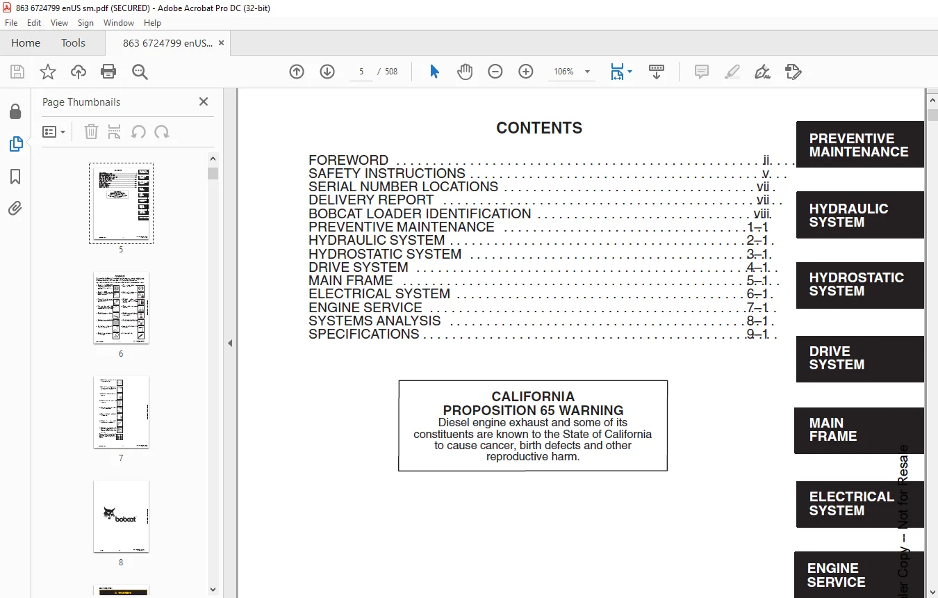
CONTENTS 5
FOREWORD 6
SAFETY INSTRUCTIONS 9
SERIAL NUMBER LOCATIONS 11
LOADER SERIAL NUMBER 11
DELIVERY REPORT 11
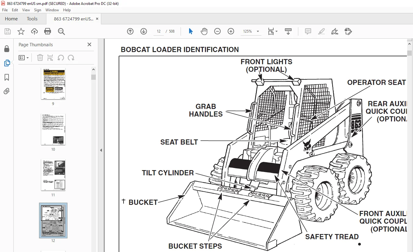
BOBCAT LOADER IDENTIFICATION 12
OPTIONS AND ACCESSORIES 13
PREVENTIVE MAINTENANCE 15
SERVICE SCHEDULE 17
LIFTING AND BLOCKING THE LOADER 18
Procedure 18
TRANSPORTING THE BOBCAT LOADER 19
Procedure 19
TOWING THE LOADER 19
LIFT ARM SUPPORT DEVICE 20
To Install The Lift Arm Support Device 20
To Remove The Lift Arm Support Device 21
OPERATOR CAB 22
Description 22
Raising The Operator Cab 22
Lowering The Operator Cab 23
Emergency Exit 23
SEAT BAR RESTRAINT SYSTEM 24
Description 24
Seat Bar Inspection 24
Seat Bar Maintenance 24
AIR CLEANER SERVICE 25
Replacing Filter Element 25
FUEL SYSTEM 27
Fuel Specifications 27
Filling The Fuel Tank 27
Fuel Filter 27
Removing Air From The Fuel System 27
ENGINE LUBRICATION SYSTEM 28
Checking Engine Oil 28
Replacement Of Oil And Filter 28
COOLING SYSTEM 29
Cleaning The Cooling System 29
ALTERNATOR BELT 30
Adjusting The Alternator Belt 30
HYDRAULIC/HYDROSTATIC SYSTEM 31
Checking And Adding Fluid 31
Replacing The Hydraulic/Hydrostatic Filter 31
Replacing The Hydraulic Fluid 32
TIRE MAINTENANCE 33
Wheel Nuts 33
Tire Rotation 33
Tire Mounting 33
FINAL DRIVE TRANSMISSION (CHAINCASE) 34
Checking And Adding Oil 34
Removing Oil From The Chaincase 34
LUBRICATION OF THE BOBCAT LOADER 35
Procedure 35
FAN GEARBOX 36
Checking And Maintaining 36
REMOTE START SWITCH 37
Procedure 37
HYDRAULIC SYSTEM 39
HYDRAULIC / HYDROSTATIC SCHEMATICS 41
TROUBLESHOOTING 53
HYDRAULIC SYSTEM INFORMATION 54
Tighten Procedures 54
LIFT CYLINDER(S) 55
Checking The Lift Cylinder(s) 55
Removal And Installation 55
TILT CYLINDER 57
Checking The Tilt Cylinder 57
Removal And Installation 57
Rod End Seal 58
HYDRAULIC CYLINDER 59
Lift Cylinder Identification 59
Tilt Cylinder Identification 60
Disassembly 61
Assembly 63
MAIN RELIEF VALVE 66
Checking The Main Relief Valve 66
Checking The Main Relief Valve Without Auxiliaries 67
Removal And Installation 68
Adjustment 68
SELECT VALVE 863H 69
Checking The High Flow Pump Relief Valve 69
Removal And Installation 70
Disassembly And Assembly 71
Solenoid Testing 72
LIFT ARM BY–PASS CONTROL VALVE 73
Removal And Installation 73
Disassembly And Assembly 74
BICS™ CONTROL VALVE 75
Removal And Installation 75
BICS™ VALVE ASSEMBLY 78
Lift Arm By–Pass Orifice 78
Check Valve 79
Lock Valve 80
BICS™ Valve Solenoid 81
HYDRAULIC CONTROL VALVE 82
Removal And Installation 82
Identification Chart 86
Disassembly And Assembly 87
Load Check Valve 87
Lift Base End Restrictor 87
Main Relief Valve 88
Port Relief Valve 89
Anti–Cavitation/Port Relief Valve 89
Rubber Boot 91
Lift Spool And Detent 92
Tilt Spool And Centering Spring 96
Auxiliary Spool 97
Auxiliary Electric Solenoid 98
H Port – Auxiliary Section 99
Inspection 99
Spool Seal Installation 100
HYDRAULIC PUMP 101
Checking The Output Of The Pump 101
Removal And Installation 102
Parts Identification 103
Disassembly 104
Inspection 106
Assembly 107
HYDRAULIC PUMP (Double Gear) 863H 109
Checking The Output Of The High Flow Pump 109
Removal And Installation 110
Parts Identification 112
Disassembly 113
Inspection 117
Assembly 118
HYDRAULIC FLUID RESERVOIR 121
Removal And Installation 121
HYDROSTATIC FILTER HOUSING 122
Removal And Installation 122
Hydrostatic Charge Pressure Sender 122
HYDRAULIC FILTER HOUSING 123
Removal And Installation 123
CONTROL PEDALS 124
Removal And Installation 124
Pedal Adjustment 124
PEDAL INTERLOCK LINKAGE 125
Removal And Installation 125
Pedal Interlock Linkage Adjustment 126
REAR AUXILIARY DIVERTER 127
Disassembly 127
Inspection 127
Solenoid Testing 127
Assembly 127
HYDROSTATIC SYSTEM 129
TROUBLESHOOTING 131
HYDROSTATIC SYSTEM INFORMATION 132
Replenishing Valve Function 132
FRONT PANEL (SOLID STEERING LINKAGE) 133
Removal And Installation 133
FRONT PANEL (CABLE STEERING LINKAGE) 135
Removal And Installation 135
STEERING LEVERS 137
Disassembly And Assembly 137
CONTROL TOWER (SOLID STEERING LINKAGE) 139
Removal And Installation 139
Disassembly And Assembly 140
SOLID STEERING LINKAGE NEUTRAL ADJUSTMENT 142
Procedure 142
CABLE STEERING LINKAGE NEUTRAL ADJUSTMENT 145
Pre–Adjustment Checks 145
Adjusting Lever Freeplay 146
Adjusting The Wheel RPM Forward Compared to Reverse Travel 147
Adjusting The Steering Neutral Setting 149
Adjusting The Wheel RPM Left Compared To Right Side 150
HYDROSTATIC MOTOR 151
Removal And Installation 151
Parts Identification 153
Disassembly 154
Inspection 157
Assembly 158
HYDROSTATIC PUMP 162
Removal And Installation 162
Replenishing/High Pressure Relief Valve 164
Parts Identification 166
Hydraulic Pump Removal 170
Hydrostatic Pump Separation 170
Charge Pump Disassembly 171
Disassembly 172
Inspection 181
Assembly 183
Charge Pump Assembly 192
Hydrostatic Pump Connection 193
Hydraulic Pump Installation 194
Swashplate Neutral Adjustment 195
Displacement Control Servo (Solid Linkage) 196
Displacement Control Servo (Cable Linkage) 197
DRIVE BELT SHIELD 199
Removal And Installation 199
DRIVE BELT 200
Adjusting The Drive Belt 200
Replacing The Drive Belt 200
DRIVE BELT TENSIONER PULLEY 201
Removal And Installation 201
Tension Spring 203
OIL COOLER 204
Removal And Installation 204
DRIVE SYSTEM 205
PARKING BRAKE PEDAL 207
Removal And Installation 207
Disassembly And Assembly 208
PARKING BRAKE DISC 209
Removal And Installation 209
FRONT CHAINCASE COVER 212
Removal And Installation 212
REAR CHAINCASE COVER 212
Removal And Installation 212
AXLE SEAL 213
Removal And Installation 213
AXLE, SPROCKET AND BEARINGS 215
Removal And Installation 215
MOTOR CARRIER 219
Shaft Seal Replacement 219
Removal And Installation 220
Parts Identification 222
Disassembly 223
Assembly 225
DRIVE CHAIN 229
Removal And Installation 229
CHAINCASE FLUID 230
Removing The Fluid From The Chaincase 230
MAIN FRAME 231
SEAT BAR (W/GAS SPRING) 233
Removal And Installation 233
Seat Bar Pivot Assembly 235
Compressing The Gas Cylinder 236
Assembly 237
SEAT BAR (W/COMPRESSION SPRING) 238
Removal And Installation 238
Assembling Components 241
Compression Spring Disassembly And Assembly 241
OPERATOR CAB GAS CYLINDER 242
Removal And Installation 242
Disassembly And Assembly 243
OPERATOR CAB 244
Removal And Installation 244
OPERATOR SEAT 246
Removal And Installation 246
BOB–TACH 247
Bob–Tach Lever And Wedge 247
Bob–Tach Stops 248
Removal And Installation 249
Pivot Pin Bushing And Seal Replacement 251
LIFT ARMS 252
Removal And Installation 252
REAR GRILL 255
Removal And Installation 255
REAR DOOR (ONE PIECE) 256
Removal And Installation 256
Door Latch And Catch Adjustment 257
REAR DOOR 258
Removal And Installation 258
Hood Removal And Installation 259
Bumper Removal And Installation 259
Door Latch Removal And Installation 259
Door Latch And Catch Adjustment 259
FUEL TANK 260
Removal And Installation 260
Fuel Level Sender 261
Fuel Pick–Up Screen/Check Valve 261
Inlet Screen 262
ELECTRICAL SYSTEM 263
ELECTRICAL SCHEMATICS 265
TROUBLESHOOTING 289
ELECTRICAL SYSTEM INFORMATION 290
Description 290
Fuse Location 290
BATTERY 291
Removal And Installation 291
Servicing The Battery 292
Using A Booster Battery 293
ALTERNATOR 294
Alternator Output Test 294
Rectifier (Diode) Test 294
Alternator Regulator Test 295
Removal And Installation 296
Disassembly 297
Stator Continuity Test 297
Stator Ground Test 297
Rotor Continuity Test 298
Rotor Ground Test 298
Rectifier Continuity (Diode) Test 298
Assembly 299
STARTER 299
Removal And Installation 299
Parts Identification 300
Disassembly And Assembly 301
External Pinion 305
Inspection And Repair 306
Magnetic Switch Test 309
No Load Test 309
STANDARD INSTRUMENT PANEL 310
Removal And Installation 310
FRONT LIGHTS 311
Removal And Installation 311
RELAY SWITCHES 312
Location 312
ENGINE SERVICE 313
TROUBLESHOOTING 315
ENGINE SPEED CONTROL 316
Removal And Installation 316
Speed Control Cable 317
Speed Control Linkage 317
ENGINE MUFFLER 318
Removal And Installation 318
AIR CLEANER HOUSING 319
Removal And Installation 319
BLOWER HOUSING/FAN GEARBOX 320
Removal And Installation 320
FAN DRIVE TENSION PULLEY 322
Removal And Installation 322
BLOWER FAN 323
Removal And Installation 323
FAN GEARBOX 324
Parts Identification 324
Disassembly 325
Assembly 330
Checking Backlash 335
ENGINE 338
Removal And Installation 338
ENGINE MOUNTS 344
Replacement 344
FLYWHEEL 345
Removal And Installation 345
Flywheel Ring Gear 345
FLYWHEEL HOUSING 345
Removal And Installation 345
GLOW PLUG 346
Checking The Glow Plug 346
VALVE CLEARANCE 347
Adjustment 347
FUEL INJECTION PUMP 348
Description 348
Removal 348
Installation 350
FUEL INJECTOR 352
Removal And Installation 352
Checking 353
Disassembly 354
Assembly 355
TIMING BELT 357
Inspection 357
Removal 357
Installation 358
Belt Replacement In Loader 361
VALVE TIMING 366
Checking 366
DEUTZ ENGINE TOOLS 367
Identification Chart 367
RECONDITIONING THE ENGINE 368
Disassembly 368
Assembly 372
CYLINDER LINERS 387
Checking The Cylinder Liners 387
CAMSHAFT BEARINGS 388
Checking 388
Removal And Installation 388
CONTROL ROD GUIDE BUSHING 390
Removal 390
Installation 392
REAR COVER SEAL 396
Removal And Installation 396
CRANKSHAFT 397
Checking The Crankshaft 397
CONNECTING ROD 398
Checking The Connecting Rod 398
PISTON AND PISTON PIN 401
Checking The Piston 401
Checking Piston Pin 402
Installing Piston Rings 402
CYLINDER HEAD 403
Disassembly 403
Checking The Valves 403
Checking Valve Seats 404
Valve Spring 404
Assembly 404
ROCKER ARM AND BRACKET 406
Checking 406
FRONT COVER 407
Disassembly 407
Assembly 412
TURBOCHARGER 422
Removal And Installation 422
Disassembly 423
Inspection 427
Assembly 428
POSITIVE CRANKCASE VENTILATION SYSTEM(S/N 514415609, 514611152, 514511106 & Below) 433
Description 433
Inspection 433
Module Removal And Installation 434
OIL COOLER 435
Removal And Installation 435
CRANKSHAFT GEAR MOUNTING BOLT 436
Torque Procedure 436
SYSTEMS ANALYSIS 437
BOBCAT INTERLOCK CONTROL SYSTEM (BICS™) 439
Inspecting The BICS™ Controller (Engine STOPPED – Key ON) 439
Inspecting Deactivation Of The Auxiliary HydraulicsSystem (Engine STOPPED – Key ON) 439
Inspecting The Seat And Seat Bar Sensors (Engine RUNNING) 439
Inspecting The Traction Lock (Engine RUNNING) 439
Inspecting The Lift Arm By–Pass Control 439
Maintenance 439
Troubleshooting Chart 440
SEAT SENSOR OVERRIDE ONLY (If Equipped) 440
Troubleshooting Guide 441
BICS SYSTEM CONTROLLER 441
TRACTION LOCK 442
SEAT SENSOR 443
SEAT BAR SENSOR 444
LIFT ARM BY–PASS VALVE 445
BICS™ SYSTEM CONTROLLER 446
Removal And Installation 446
Controller Test 447
SEAT BAR SENSOR 448
Removal And Installation 448
Seat Bar Sensor Test 449
SEAT SENSOR 450
Removal And Installation 450
Seat Sensor Test 451
TRACTION LOCK 452
Removal And Installation 452
BOSS® DIAGNOSTIC TOOL 453
Procedure 453
SENDER AND SENSOR 453
Service Checks 453
Components 453
RPM SENSOR 453
Adjustment 453
MONITOR SERVICE CODES 454
TROUBLESHOOTING THE BOSS® & LCD DISPLAY 457
OPERATION SENSING SYSTEM UNIT 458
Removal And Installation 458
BOSS® INSTRUMENT PANEL 459
Removal And Installation 459
PWM MODULE 460
Description 460
Troubleshooting Chart 462
PWM CONTROL HANDLE 463
Handle Testing 463
PWM ELECTRIC SOLENOID 463
Solenoid Coil Testing 463
ELECTRICAL/HYDRAULIC CONTROLS REFERENCE 464
Controls Identification Chart 464
SPECIFICATIONS 465
LOADER SPECIFICATIONS 467
LOADER DIMENSIONS 467
PERFORMANCE 467
CONTROLS 467
ENGINE 467
HYDRAULIC SYSTEM 468
ELECTRICAL 468
DRIVE SYSTEM 468
CAPACITIES 469
TIRES 469
ENGINE SPECIFICATIONS (BF4M1011) 470
General 470
Fuel System 470
Valve And Valve Guide And Seat Insert 470
Piston And Rings 471
Connecting Rod 471
Cylinder Head And Block 471
Crankshaft And Main Bearings 472
Camshaft And Bearings 472
Oil Pump 472
ENGINE SPECIFICATIONS (BF4M1011F) 473
General 473
Fuel System 473
Valve And Valve Guide And Seat Insert 473
Piston And Rings 474
Connecting Rod 474
Crankshaft And Main Bearings 475
Camshaft And Bearings 475
Oil Pump 475
ENGINE TORQUE 476
Specifications 476
Torque For General Metric Bolts 477
TORQUE SPECIFICATIONS FOR LOADER 478
HYDRAULIC CONNECTION SPECIFICATIONS 479
O–ring Face Seal Connection 479
Straight Thread O–ring Fitting 479
Tubelines And Hoses 479
Flare Fitting 479
O–ring Flare Fitting 480
Port Seal Fitting 482
HYDRAULIC/HYDROSTATIC FLUID SPECIFICATIONS 483
STANDARD TORQUE SPECIFICATIONS FOR BOLTS 484
DECIMAL AND MILLIMETER EQUIVALENTS 485
U S TO METRIC CONVERSION 485
SERVICE MANUAL REVISIONS 487
863–001 487
863–002 489
863–003 491
863–004 493
863–005 495
863–006 497
863–007 499
863–008 501
863–009 503
863-010 505
863-011 507
DESCRIPTION:
Bobcat 863 & 863 High Flow Loader Service Manual 6724799 (10-12) – PDF DOWNLOAD
(S/N 514411001–514424999)
(S/N 514511001–514524999)
(S/N 514611001–514624999)
FOREWORD:
This manual is for the Bobcat loader mechanic. It provides necessary servicing and adjustment procedures for the Bobcat loader and its component parts and systems. Refer to the Operation & Maintenance Manual for operating instructions, starting procedure, daily checks, etc.
SAFETY INSTRUCTIONS
The following publications provide information on the safe use and maintenance of the loader and attachments:
• The Delivery Report is used to assure that complete instructions have been given to the new owner and that the machine
is in safe operating condition.
• The Operation & Maintenance Manual delivered with the loader gives operating information as well as routin e
maintenance and service procedures. It is a part of the loader and must stay with the machine when it is sold. Replacement
Operation & Maintenance Manuals can be ordered from your Bobcat loader dealer.
• The loader has machine signs (decals) which instruct on the safe operation and care. The signs and their locations are
shown in the Operation & Maintenance Manual. Replacement signs are available from your Bobcat loader dealer.
• The loader has a plastic Operator’s Handbook fastened to the operator cab. Its brief instructions are convenient to the
operator. The Handbook is available from your dealer in an English edition or one of many other languages. See your
Bobcat dealer for more information on translated versions.
• The EMI Safety Manual (available in Spanish) delivered with the loader gives general safety information.
• The Service Manual and Parts Manual are available from your dealer for use by mechanics to do shop–type service and
repair work.
• The Skid–Steer Loader Operator Training Course is available through your local dealer. This course is intended to provide
rules and practices for correct operation of the Bobcat loader. The course is available in English and Spanish version.
• The Service Safety Training Course is available from your Bobcat dealer. This course provides information for safe and
correct service procedures for Bobcat Skid–Steer loaders.
• The Bobcat Skid–Steer Loader Safety Video is available from your Bobcat Dealer.
Contact us: [email protected]
IMAGES PREVIEW OF THE MANUAL:
PLEASE NOTE:
- This is the SAME manual used by the dealers to troubleshoot any faults in your vehicle. This can be yours in 2 minutes after the payment is made.
- Contact us at [email protected] should you have any queries before your purchase or that you need any other service / repair / parts operators manual.
S.V