Bobcat 873 Loader Service Manual 6724280 (7-10) – PDF DOWNLOAD
$30.95
Bobcat 873 Loader Service Manual 6724280 (7-10) – PDF DOWNLOAD
(S/N 514114999 & Below)
(S/N 514212999 & Below)
Description
Bobcat 873 Loader Service Manual 6724280 (7-10) – PDF DOWNLOAD
FILE DETAILS:
Bobcat 873 Loader Service Manual 6724280 (7-10) – PDF DOWNLOAD
Language : English
Pages : 508
Downloadable : Yes
File Type : PDF
TABLE OF CONTENTS:
Bobcat 873 Loader Service Manual 6724280 (7-10) – PDF DOWNLOAD
MAINTENANCE SAFETY 3
ALPHABETICAL INDEX 5
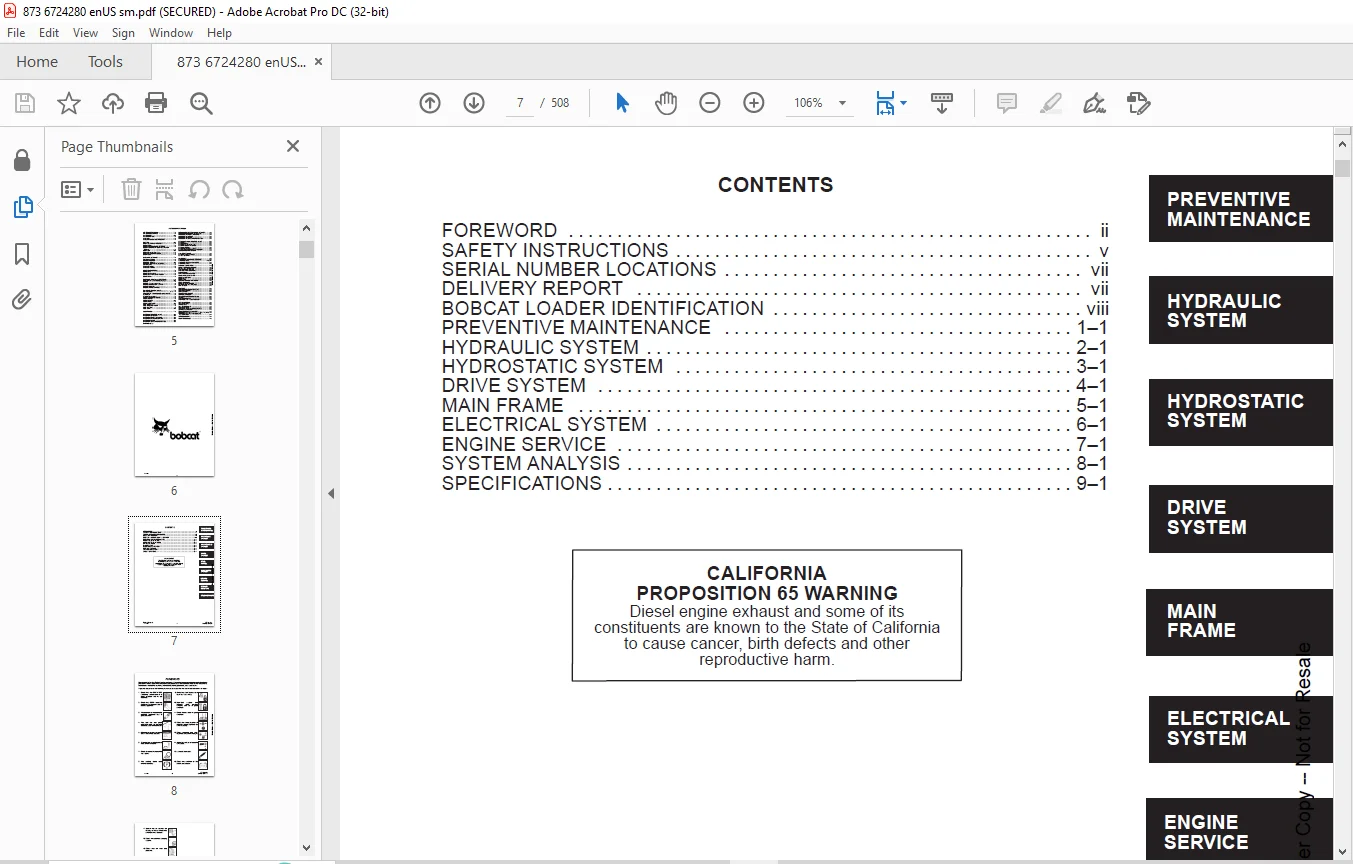
CONTENTS 7
FOREWORD 8
SAFETY INSTRUCTIONS 11
SERIAL NUMBER LOCATIONS 13
LOADER SERIAL NUMBER 13
ENGINE SERIAL NUMBER 13
DELIVERY REPORT 13
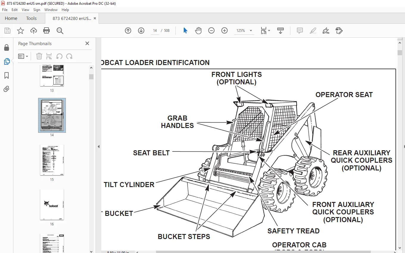
BOBCAT LOADER IDENTIFICATION 14
OPTIONS AND ACCESSORIES 15
PREVENTIVE MAINTENANCE 17
SERVICE SCHEDULE 19
LIFTING AND BLOCKING THE LOADER 20
Procedure 20
TRANSPORTING THE LOADER 21
Procedure 21
TOWING THE LOADER 21
Procedure 21
STOPPING THE BOBCAT LOADER 21
Procedure 21
LIFT ARM SUPPORT DEVICE 22
To Install The Lift Arm Support Device 22
To Remove The Lift Arm Support Device 22
OPERATOR CAB 23
Description 23
Raising The Operator Cab 23
Lowering The Operator Cab 24
Emergency Exit 25
SEAT BAR RESTRAINT SYSTEM 26
Description 26
Seat Bar Inspection 26
Seat Bar Maintenance 26
AIR CLEANER SERVICE 27
Replacing Filter Element 27
FUEL SYSTEM 29
Fuel Specifications 29
Filling The Fuel Tank 29
Fuel Filter 29
Removing Air From The Fuel System 29
ENGINE LUBRICATION SYSTEM 30
Checking Engine Oil 30
Replacing Oil And Filter 30
ENGINE COOLING SYSTEM 31
Cleaning Cooling System (S/N 514111516 – 514114999) 31
Cleaning The Cooling System (S/N 514111515 & Below) 32
ALTERNATOR BELT 33
Adjusting The Alternator Belt 33
HYDRAULIC/HYDROSTATIC SYSTEM 34
Checking And Adding Fluid 34
Hydraulic/Hydrostatic Filter Replacement 34
Replacing Hydraulic Fluid 35
TIRE MAINTENANCE 36
Wheel Nuts 36
Tire Rotation 36
Tire Mounting 36
FINAL DRIVE TRANSMISSION (CHAINCASE) 37
Checking And Adding Oil 37
FAN GEARBOX 37
Checking And Maintaining 37
LUBRICATING THE LOADER 38
Procedure 38
REMOTE START SWITCH 41
Procedure 41
HYDRAULIC SYSTEM 43
HYDRAULIC / HYDROSTATIC SCHEMATICS 46
TROUBLESHOOTING 49
HYDRAULIC SYSTEM INFORMATION 50
Flare Connections 50
O–ring Face Seal Connection 50
Straight Thread O–ring Fitting 50
Tubelines And Hoses 50
LIFT CYLINDER(S) 51
Checking The Lift Cylinder(s) 51
Removal And Installation 51
TILT CYLINDER(S) 53
Checking The Tilt Cylinder(s) 53
Removal And Installation 54
HYDRAULIC CYLINDER 56
Lift Cylinder Identification 56
Tilt Cylinder Identification 57
Disassembly 58
Assembly 60
MAIN RELIEF VALVE 63
Checking The Main Relief Valve 63
Checking The Main Relief Valve Without Auxiliaries 64
Removal And Installation 65
HYDRAULIC CONTROL VALVE 66
Removal And Installation 66
Identification Chart 68
Disassembly And Assembly 69
Load Check Valve 69
Main Relief Valve 70
Port Relief Valve 70
Anti–Cavitation Valve 71
Rubber Boot 72
Lift Spool And Detent 73
Tilt Spool And Centering Spring 78
Auxiliary Spool 79
Auxiliary Electric Solenoid 80
H Port – Auxiliary Section 81
Base End Restrictor 81
Inspection 81
Spool Seal Installation 82
HYDRAULIC PUMP 83
Checking The Output Of The Pump 83
Removal And Installation 84
Parts Identification 85
Disassembly 86
Inspection 88
Assembly 89
HYDRAULIC FLUID RESERVOIR 91
Draining The Fluid Reservoir 91
Removal And Installation 91
HYDROSTATIC FILTER HOUSING 94
Removal And Installation 94
HYDRAULIC FILTER HOUSING 95
Removal And Installation 95
HYDRAULIC/HYDROSTATIC FILTER HOUSING BRACKET 96
Removal And Installation 96
CONTROL PEDALS 98
Removal And Installation 98
Pedal Adjustment 98
PEDAL INTERLOCK LINKAGE 99
Removal And Installation 99
Pedal Interlock Linkage Adjustment 100
FRONT SIDE PANEL 100
Removal And Installation 100
REAR AUXILIARY DIVERTER 101
Disassembly 101
Inspection 101
Solenoid Testing 101
Assembly 101
HYDROSTATIC SYSTEM 103
TROUBLESHOOTING 105
HYDROSTATIC SYSTEM INFORMATION 106
Replenishing Valve Function 106
FRONT PANEL 107
Removal And Installation 107
STEERING LEVERS 109
Disassembly And Assembly 109
Pre–Adjustment Checks 111
Adjusting Lever Freeplay 112
Adjusting The Wheel RPM Forward Compared To Reverse Travel 113
Adjusting The Steering Neutral Setting 115
Adjusting The Wheel RPM Left Compared To Right Side 116
HYDROSTATIC MOTOR 117
Removal And Installation 117
Parts Identification 119
Disassembly 120
Inspection 121
Assembly 122
MOTOR CARRIER 124
Removal And Installation 124
Parts Identification 126
Disassembly 127
Assembly 129
HYDROSTATIC PUMP 131
Removal And Installation 131
Replenishing/High Pressure Relief Valve 133
Parts Identification 134
Hydraulic Pump Removal 138
Hydrostatic Pump Separation 138
Charge Pump Disassembly 139
Disassembly 140
Inspection 149
Assembly 151
Charge Pump Assembly 160
Hydrostatic Pump Connection 161
Hydraulic Pump Installation 162
Hydrostatic Pump Neutral Adjustment 163
DRIVE BELT SHIELD 165
Removal And Installation 165
DRIVE BELT 166
Adjusting The Drive Belt 166
Replacing The Drive Belt 166
DRIVE BELT TENSIONER PULLEY 167
Removal And Installation 167
Tension Spring 169
OIL COOLER 170
Removal And Installation (*S/N 514111516 – 514114999) (*Also S/N 514111504) 170
Removal And Installation (S/N 514111515 & Below) 171
DRIVE SYSTEM 173
BRAKE PEDAL 175
Removal And Installation 175
Disassembly And Assembly 176
BRAKE DISC 177
Removal And Installation 177
Removal And Installation (New Style Disc) 178
Removal And Installation (Old Style Disc) 180
FRONT CHAINCASE COVER 181
Removal And Installation 181
REAR CHAINCASE COVER 181
Removal And Installation 181
AXLE SEAL 182
Removal And Installation 182
AXLE, BEARINGS AND SPROCKET 184
Removal And Installation 184
DRIVE CHAIN 188
Removal And Installation 188
Removing The Fluid From The Chaincase 189
MAIN FRAME 191
SEAT BAR (W/GAS SPRING) 193
Removal And Installation 193
Assembly 195
Compressing The Gas Cylinder 196
SEAT BAR (W/COMPRESSION SPRING) 198
Removal And Installation 198
Assembling Components 201
Compression Spring Disassembly And Assembly 201
OPERATOR CAB GAS CYLINDER 202
Removal And Installation 202
Disassembly And Assembly 203
OPERATOR CAB 204
Removal And Installation 204
OPERATOR SEAT 207
Removal And Installation 207
BOB–TACH 208
Removal And Installation 208
Bob–Tach Lever And Wedge 209
Pivot Pin Bushing And Seal Replacement 210
LIFT ARM STABILIZER BAR 211
Removal And Installation 211
LIFT ARM LINK 212
Removal And Installation 212
LIFT ARMS 214
Removal And Installation 214
REAR GRILL 217
Removal And Installation 217
REAR DOOR 218
Removal And Installation 218
Hood Removal And Installation 219
Bumper Removal And Installation 219
Door Latch Removal And Installation 219
Door Latch And Catch Adjustment 219
FUEL TANK 220
Removal And Installation 220
Fuel Level Sender 222
Inlet Screen 222
ELECTRICAL SYSTEM 223
ELECTRICAL SCHEMATICS 225
TROUBLESHOOTING 297
ELECTRICAL SYSTEM INFORMATION 298
Description 298
Fuse Location 298
BATTERY 299
Removal and Installation 299
Servicing the Electrical System 301
Using A Booster Battery (Jump Starting) 302
ALTERNATOR 303
Alternator Output Test 303
Rectifier (Diode) Test 303
Alternator Regulator Test 304
Removal and Installation 305
Disassembly 306
Stator Continuity Test 306
Stator Ground Test 306
Rotor Continuity Test 307
Rotor Ground Test 307
Rectifier Continuity (Diode) Test 307
Assembly 308
STARTER 309
Removal and Installation 309
Parts Identification 310
Disassembly and Assembly 311
External Pinion 315
Inspection and Repair 316
Magnetic Switch Test 319
No Load Test 319
STANDARD INSTRUMENT PANEL 320
Removal and Installation 320
FRONT LIGHTS 321
Removal and Installation 321
RELAY SWITCHES 322
Location 322
ENGINE SERVICE 323
TROUBLESHOOTING 325
ENGINE SPEED CONTROL 326
Removal And Installation 326
Speed Control Cable 327
Speed Control Linkage 327
ENGINE MUFFLER 328
Removal And Installation 328
AIR CLEANER HOUSING 329
Removal And Installation 329
BLOWER HOUSING/FAN GEARBOX 331
Removal And Installation 331
FAN DRIVE TENSION PULLEY 333
Removal And Installation 333
BLOWER FAN 335
Removal And Installation 335
FAN GEARBOX 336
Parts Identification 336
Disassembly 337
Assembly 342
Checking Backlash 347
ENGINE/HYDROSTATIC PUMP ASSEMBLY 349
Removal And Installation 349
ENGINE MOUNTS 355
Replacement 355
ENGINE 356
Removal And Installation 356
FLYWHEEL 358
Removal And Installation 358
FLYWHEEL HOUSING 358
Removal And Installation 358
GLOW PLUG 359
Checking The Glow Plug 359
VALVE CLEARANCE 360
Adjustment 360
FUEL INJECTION PUMP 361
Description 361
Removal 361
Installation 363
FUEL INJECTOR 365
Removal And Installation 365
Checking 366
Disassembly 367
Assembly 368
TIMING BELT 370
Inspection 370
Removal 370
Installation 371
Belt Replacement In Loader 374
VALVE TIMING 379
Checking 379
DEUTZ ENGINE TOOLS 380
Identification Chart 380
RECONDITIONING THE ENGINE 381
Disassembly 381
Assembly 385
CYLINDER LINERS 400
Checking The Cylinder Liners 400
CAMSHAFT BEARINGS 401
Checking 401
Removal And Installation 401
CONTROL ROD GUIDE BUSHING 403
Removal 403
Installation 405
REAR COVER SEAL 409
Removal And Installation 409
CRANKSHAFT 410
Checking The Crankshaft 410
CONNECTING ROD 411
Checking The Connecting Rod 411
PISTON AND PISTON PIN 414
Checking The Piston 414
Checking Piston Pin 415
Installing Piston Rings 415
CYLINDER HEAD 416
Disassembly 416
Checking The Valves 416
Checking Valve Seats 417
Valve Spring 417
Assembly 417
ROCKER ARM AND BRACKET 419
Checking 419
FRONT COVER 420
Disassembly 420
Assembly 425
TURBOCHARGER 435
Removal And Installation 435
Disassembly 436
Inspection 440
Assembly 441
POSITIVE CRANKCASE VENTILATION SYSTEM 446
Description 446
Inspection 446
Module Removal And Installation 447
OIL COOLER 448
Removal and Installation 448
CRANKSHAFT GEAR MOUNTING BOLT 449
Torque Procedure 449
SYSTEMS ANALYSIS 451
BOBCAT INTERLOCK CONTROL SYSTEM (BICS™) 453
Inspecting The BICS™ Controller (Engine STOPPED– Key ON) 453
nspecting Deactivation Of The Auxiliary HydraulicsSystem (Engine STOPPED – Key ON) 453
Inspecting The Seat And Seat Bar Sensors (Engine RUNNING) 453
Inspecting The Traction Lock (Engine RUNNING) 453
Inspecting The Lift Arm By–Pass Control 453
Maintenance 453
Troubleshooting Chart 454
Troubleshooting Guide 455
BICS SYSTEM CONTROLLER 455
TRACTION LOCK 456
SEAT SENSOR 457
SEAT BAR SENSOR 458
LIFT LOCK BY–PASS VALVE 459
BICS™ SYSTEM CONTROLLER 460
Removal And Installation 460
Controller Test 461
SEAT BAR SENSOR 462
Removal And Installation 462
Seat Bar Sensor Test 463
SEAT SENSOR 464
Removal And Installation 464
Seat Sensor Test 465
TRACTION LOCK 466
Removal And Installation 466
LIFT LOCK BY–PASS VALVE 467
Removal And Installation 467
Disassembly And Assembly 468
TILT LOCK VALVE 469
Removal And Installation (S/N 514111092 & Below) 469
Removal And Installation (S/N 514111093 – 514114999) 469
Disassembly And Assembly 470
BOSS® DIAGNOSTIC TOOL 471
Procedure 471
SENDER AND SENSOR 471
Service Checks 471
Components 471
RPM SENSOR 471
Adjustment 471
MONITOR SERVICE CODES 472
TROUBLESHOOTING THE BOSS® & LCD DISPLAY 475
OPERATION SENSING SYSTEM UNIT 476
Removal And Installation 476
BOSS® INSTRUMENT PANEL 477
Removal And Installation 477
PWM MODULE(*S/N 514111443 –514114999) (*Except S/N 514111445) 478
Description 478
PWM TROUBLESHOOTING 479
Conditions 479
Chart 480
PWM CONTROL HANDLE 481
Handle Testing 481
PWM ELECTRIC SOLENOID 481
Solenoid Coil Testing 481
TRACTION LOCK CONTROL SYSTEM 482
Description 482
Inspection 482
Maintenance 482
ELECTRICAL/HYDRAULIC CONTROLS REFERENCE 483
Controls Identification Chart 483
SPECIFICATIONS 485
LOADER SPECIFICATIONS 487
PERFORMANCE 487
CONTROLS 487
ENGINE 487
HYDRAULIC SYSTEM 488
ELECTRICAL 488
DRIVE SYSTEM 488
CAPACITIES 488
TIRES 488
FLOOR PRESSURE 488
ENGINE SPECIFICATIONS 489
General 489
Fuel System 489
Valve and Valve Guide & Seat Insert 489
Piston, Rings and Connecting Rod 489
Cylinder Head 490
Crankshaft and Main Bearings 490
Camshaft and Bearings 490
Oil Pump 490
Engine Torque Specifications 491
Torque for General Metric Bolts 492
TORQUE SPECIFICATIONS FOR LOADER 493
HYDRAULIC/HYDROSTATIC FLUID SPECIFICATIONS 494
STANDARD TORQUE SPECIFICATIONS FOR BOLTS 495
DECIMAL AND MILLIMETER EQUIVALENTS 496
U S TO METRIC CONVERSION 496
SERVICE MANUAL REVISIONS 497
873–001 497
873–002 499
873–003 501
873–004 503
873–005 505
873-6 507
DESCRIPTION:
Bobcat 873 Loader Service Manual 6724280 (7-10) – PDF DOWNLOAD
(S/N 514114999 & Below)
(S/N 514212999 & Below)
FOREWORD:
This manual is for the Bobcat loader mechanic. It provides necessary servicing and adjustment procedures for the Bobcat loader and its component parts and systems. Refer to the Operation & Maintenance Manual for operating instructions, starting procedure, daily checks, etc.
SAFETY INSTRUCTIONS:
The following publications provide information on the safe use and maintenance of the loader and attachments:
• The Delivery Report is used to assure that complete instructions have been given to the new owner and that the machine
is in safe operating condition.
• The Operation & Maintenance Manual delivered with the loader gives operating information as well as routine
maintenance and service procedures. It is a part of the loader and must stay with the machine when it is sold. Replacement
Operation & Maintenance Manuals can be ordered from your Bobcat loader dealer.
• The loader has machine signs (decals) which instruct on the safe operation and care. The signs and their locations are
shown in the Operation & Maintenance Manual. Replacement signs are available from your Bobcat loader dealer.
• The loader has a plastic Operator’s Handbook fastened to the operator cab. Its brief instructions are convenient to the
operator. The handbook is available from your dealer in an English edition or one of the following languages: French,
German, Italian, Dutch, Spanish, Portuguese, Finnish, Danish & Swedish.
• The EMI Safety Manual (available in Spanish) delivered with the loader gives general safety information.
• The Service Manual and Parts Manual are available from your dealer for use by mechanics to do shop–type service and
repair work.
• The Skid–Steer Loader Operator Training Course is available through your local dealer. This course is intended to provide
rules and practices for correct operation of the Bobcat loader. The course is available in English and Spanish versions
Need help? Contact: [email protected]
IMAGES PREVIEW OF THE MANUAL:
PLEASE NOTE:
- This is the same manual used by the DEALERSHIPS to SERVICE your vehicle.
- The manual can be all yours – Once payment is complete, you will be taken to the download page from where you can download the manual. All in 2-5 minutes time!!
- Need any other service / repair / parts manual, please feel free to contact us at heydownloadss @gmail.com . We may surprise you with a nice offer
S.V


